Mudra
Aiming the towards the Synergic growth by Virtual Currency
Introducing the virtual currency for FABLAB Vigyan Ashram
Note: document is constantly being updated
In economics, a local currency, is a currency that can be spent a particular area at participating organisations. Usually it will act as a complementary currency, that is to be used in addition to a national currency, rather than replace it. The purpose is to encourage spending within the local community, especially with locally owned businesses. This may also help reduce environmental footprints.
Mudra will offer you the way store and protect the real money under the hood. The Mudra is a type of virtual currenct which you can buy, sell and use to purchase the goods in the local market.
Inspiration
Project's objective is to provide the flawless flow of money using the concept of local currency. The Mudra will be the currency used for Vigyam Ashram fablab and it's functions primarily. Upbringing the use of local currency will help in above mentioned advantages.
The Vigyan Ashram is the home of 60 individuals. We use shared spaces to live here. Here, we have 3/4 students sharing a room, that's because we students usually faces the problems mentioned below.
- Theft
- No tracking of expenses
- Going to village for petty reasons - daily supplies and creating problems etc.
On top of that we have to control the flow of currency for the wellbeing of students as well as the Vigyan Ashram. Having virtual currency will help Vigyan Ashram to controll the money rolling in and out in campus. Following are the advantages.
- Money flow control
- Control over the supplies of some intoxication substances
- Vigyan Ashram can study the behavior of students thereby preventing damage/accidents
- Preventing the theft
- Individual student can keep track of their own expenses with ease
- Even if you have 1 mn or 1 bn, wallet size remains same
- There's no risk of receiving any fake currency notes
The project is devided into following parts:
- Software Development (development of website, and web interface for transaction)
- Hardware Development (development of the POS terminal)
Software Development
The software development cycle of this project is quite complicated, which includes the maintaining the database of each and every user, maintaning the each and every transaction happed over the network. The software side will basically include the following very important pointers
- SQL database
- JavaScript/php/python
- Web framework for UI generation
Flowchart

Process of transaction
- Shopkeeper scans the card to Mudra POS
- Shopkeeper enter the amount to which he wants to receive & asks user to enter the password
- Credentials are verified using the database stored on cloud, if it is correct one receives the SMS about the successfull payment
Project planning Gantt chart

Hardware Development
When you want to use your Mudras to purchase an amenity the one have to have the terminal which will be used to detect the use using the user's identification number. Here I'm listing out the elementry things
- POS - Point of sale terminal
- Micro-controller (Atmega 168/328)
- Keypad (an input device)
- Screen (a ouput device)
- Card Reader
- LED indicators
- Communication Device (GSM Modem)
- Battery
- RFID/NFC cards
Sketch of the proposed hardware
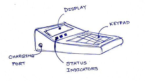
Above image gives look at the hardware which will be availble for the individual vendors to make transaction. This device is able to read the data from the customer's Mudra card, the Mudra card is the link between the user and their account where all the money is stored.
As described basic hardware infrastructure involves the two major components. 1. POS which is point of sale terminal and 2. RFID cards. Now, let's dive into details.
1. POS terminal
This device will be used as the payment gateway where one can swipe the card. The construction of the POS system is as follows,
1. Micro-controller:
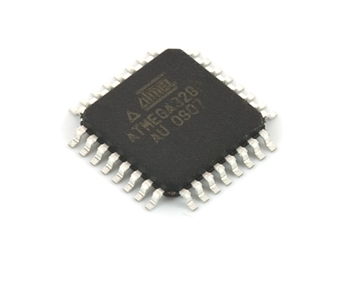
I'll be using custom designed Atmega 168 or 328 board, which is specially developed to have interfacing pin outlay to get connected to peripherals(keypad, LEDs, GSM Modem). GPIOs pins will be connected to the keypad which is 4X4 keypad which can be used to enter the user credentials and the amount during the transaction. The reason behind choosing the Atmega 328 or 168, first both micro-controller is compatible with Arduino IDE which makes the coding process quite easy on top of that it has got some extra pins to attach the extra components other than what is planned, that's what I have extra room to expand capabilities of POS.
2. Keypad:
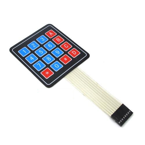
When you goto shop and you have to pay money but how POS will understand the quantum? yes, for entering the amount which one needs to receive or send. The keypad is having 4 rows and 4 columns, which comprises of 0 to 9 digits and A to F buttons, digits(0-9) will be for entering the amount and password and alphabet buttons(A-F) will be renamed to the appropriate function such as (enter, delete, cancel, reset, connectivity test, etc.)
3. Screen:
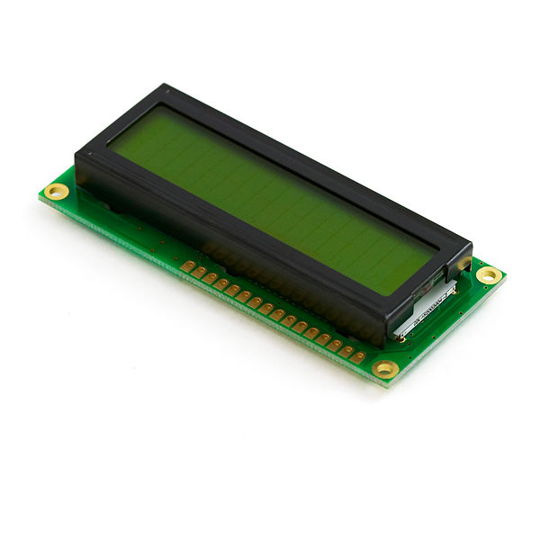
The screen is placed on POS to give prompt the user about the process which is taking place. It will show the vital messages and instructions to carry out the process. I'll be using 16X2 lcd which is commonly available in market and pretty ease to interface with micro-controller. 16X2 LED display has two methods to make it work, one is 8-bit mode and other is 4-bit mode. I'll be using 4-bit mode which will reduce the overhead of connections resulting into easy to troubleshoot.
3. Card Reader:
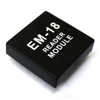
Card reader is the component which makes the POS to read the Mudra card shown to it. The card reader will use the EM18 chip which is capable of reading 125kHz RFID tag. The RFID tag's number is linked with the user and their Mudra account. EM18 works on 5V supply. Once the card is swiped successfully then shopkeeper is allowed to enter the amount and can forwarded to the authentication process. When user enters the password for the transaction then POS sends this data towards server where all of this data is validated and request is processed, thereby generating status message which will get displayed on the POS screen.
4. LED indicators:
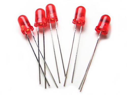
There will be two LED indicators which will dedicated to the show the power ON status and the network availability status.
5. Communication Device:
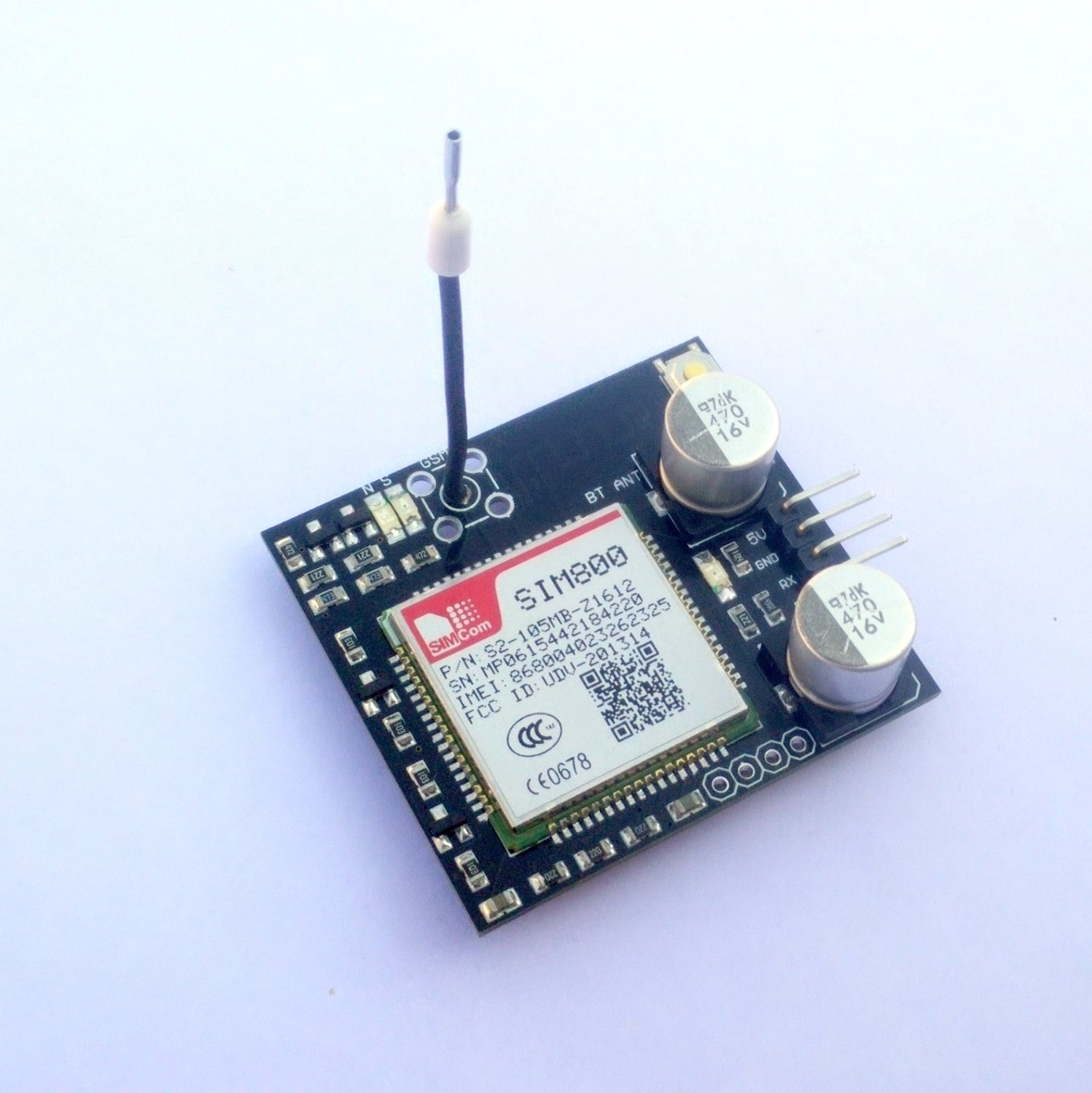
To make the device enable to get connected to cloud POS will take the help from the fellow SIM800. SIM800 is the simcom's product which is the GSM/GPRS module. I'll be using some ready made PCB available on Amazon or at local retailer to make the project development easier.
6. Battery:
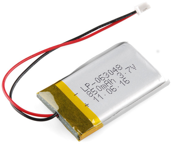
Yeah, the last but not list, as it is the battery powered device I'll be using lithium polymer(LiPo) batteries, because of it's smaller and lighter form factor, and power density is quite high compared to commercially available battery technologies. The battery will be using the boost circuit as the single cell of the LiPo's rated voltage is 3.7V and I have EM18 which needs 5V for it's operation.
Block Diagram

This block diagram shows the function of the Mudra POS. Main controlling element which controls all the actions of POS is the modified satsha kit. Which hosts Atmega328 controller. GSM module is present to make the POS talk to the centralized server using GPRS service. This service is commonly available every where so, I used that. The powering of the entire system is bit interesting, I wanted to have the weight of the device as little as possible hence I used the Lithium Polymer battery which is really very tiny. The single cell Lithium Polymer batter gives out 3.7 V nominal and 4.2 V when completely charged. The range of voltages I'm getting are not compatible for my GSM module hence I boosted the voltage levels using the boost circuit right after the battery.
Whole unit is getting powered by one Lithium Polymer battery of 500mAh.
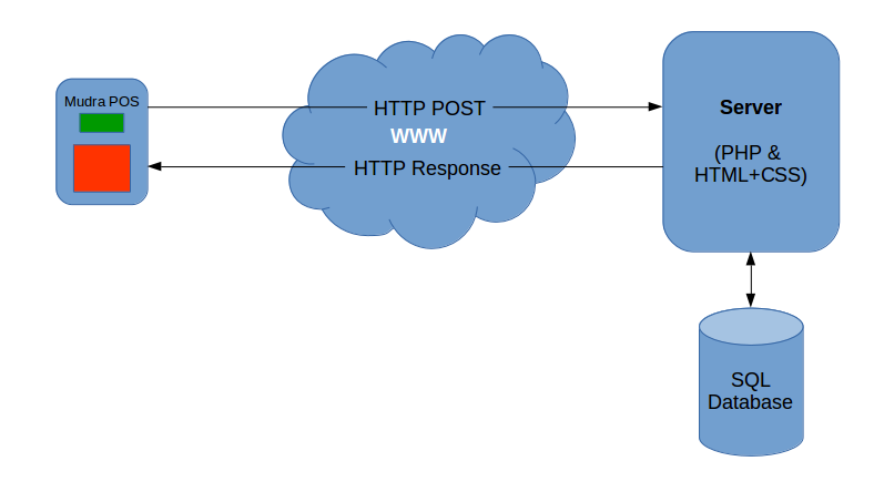
Server side I've used the SQL database which is the centralized database for all the users. Database maintains two separate tables to store the account details. One is used to store user credentials and other is used to store the account details. I've used HTML and CSS to make the user interface, the interface is pretty simple to understand. I've used icons to denote the function as pictorial things can be quickly grasped and remembered by the used.
The for taking care of the data flow, I've used the PHP script here, which is responsible for delivering the data back and forth displaying the error messages and redirection if user is trying to access the zone which he/she is not intended. PHP creates session for when somebody loggs in and keep alive that session, this adds the extra ayer of security to the user.
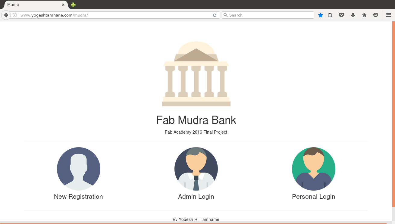
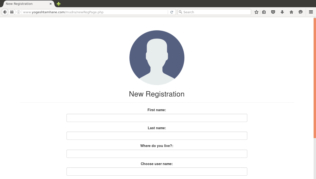
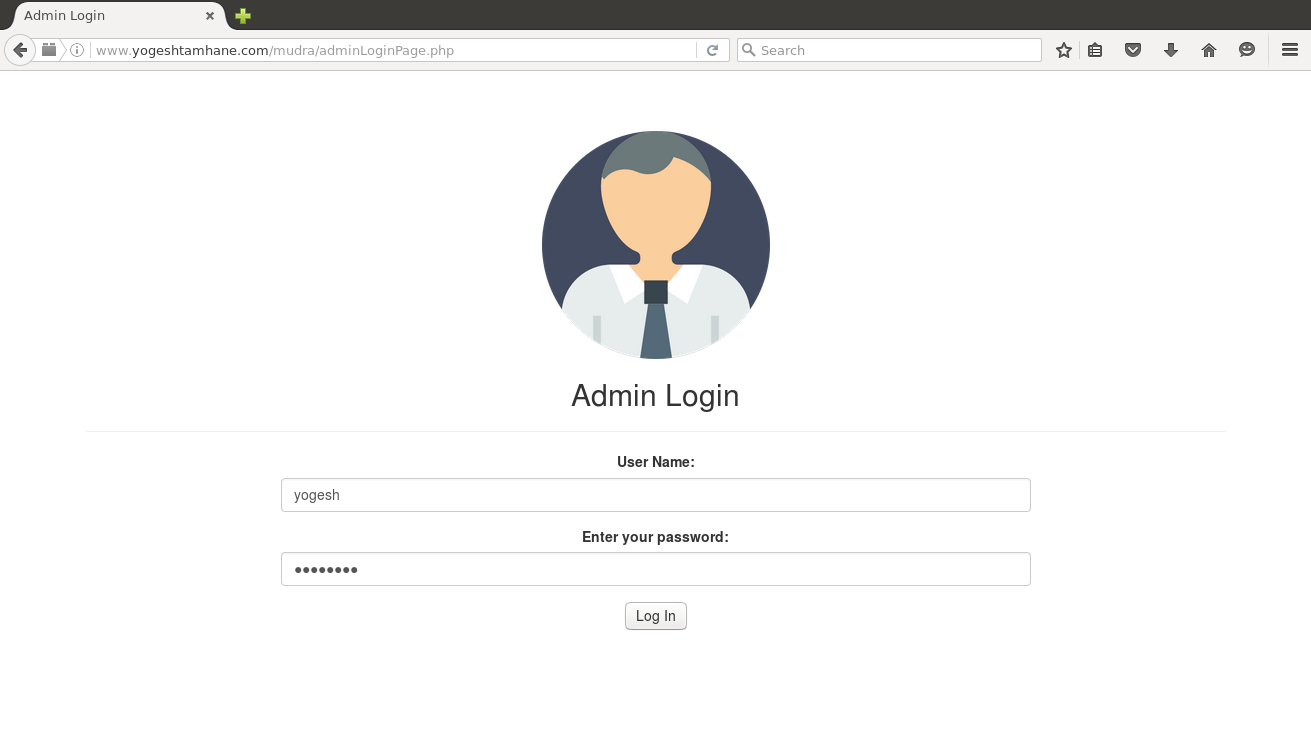
Screenshots

Circuit Diagrams
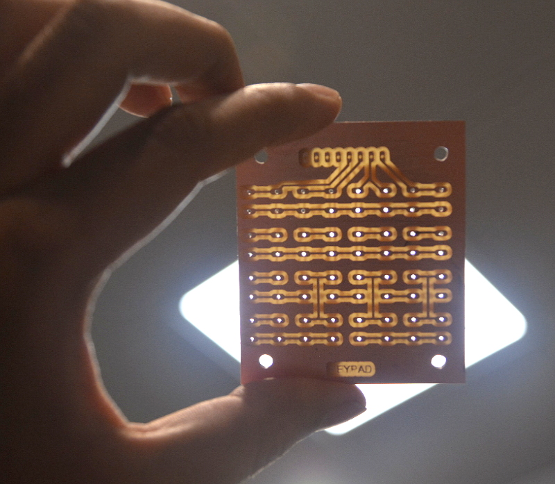
Keypad
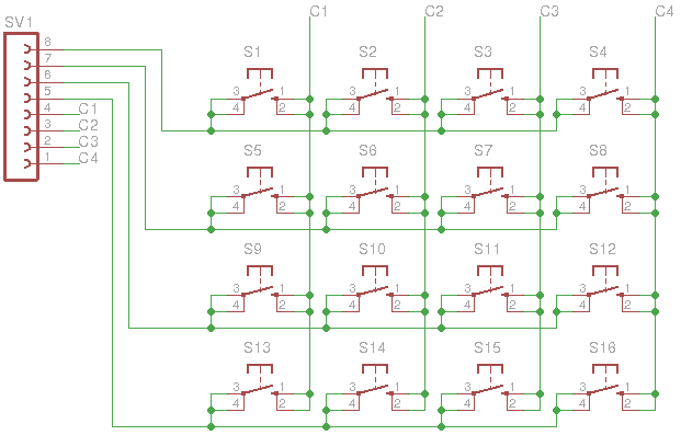
Picture beside the circuit diagram for the keypad which I've made. It's a 16 key matrix keypad, these all 16 keys are used to navigate through the menu and enter passwords and transaction amount. I've used 16, 6mm buttons to make this keypad. The artwork for the keypad I made using the kokopelli software which.
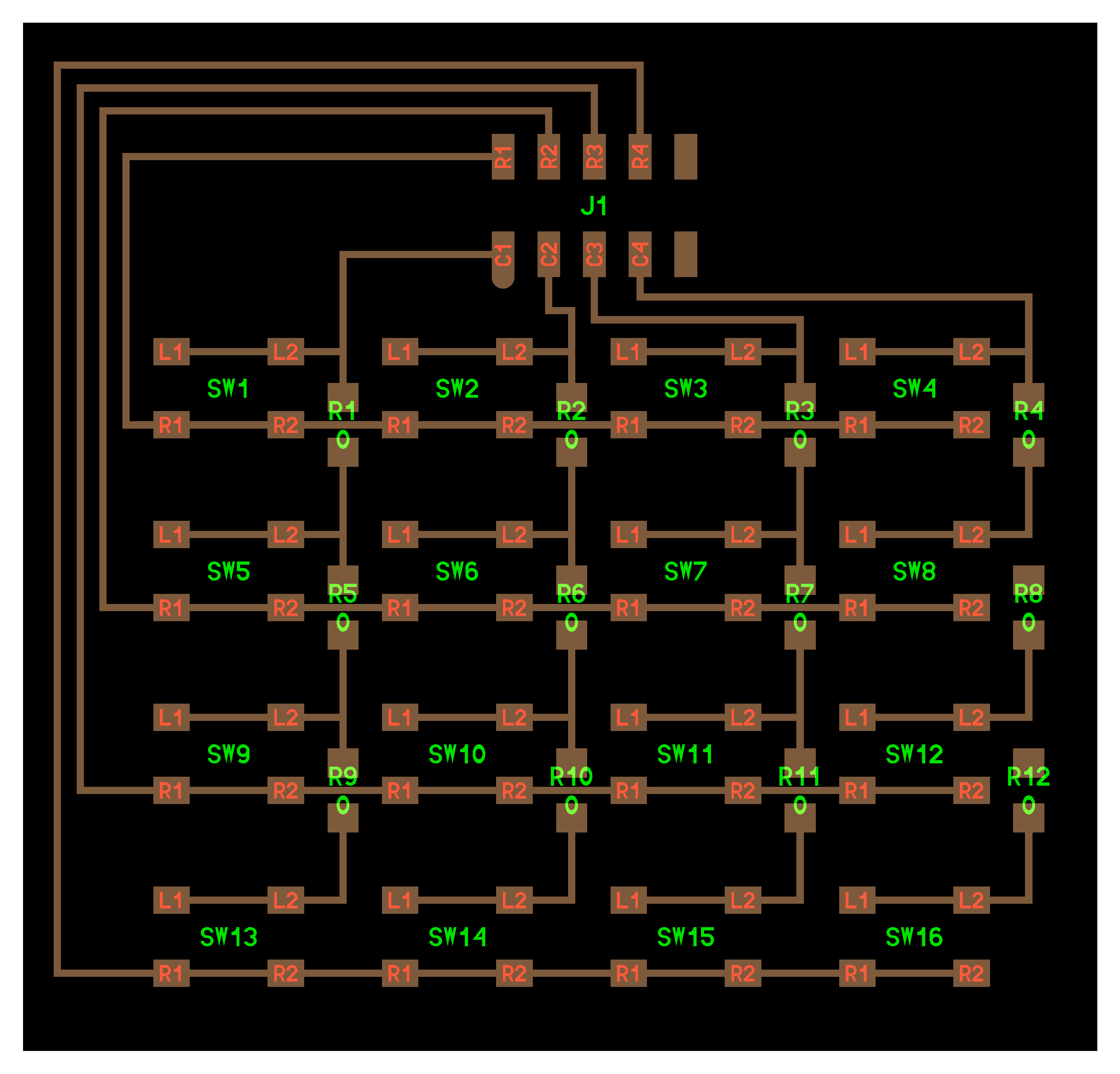
The keypad is connected to the main board using the FRC cable of configuration 5x2. The use of FRC eliminates the hassle of connecting the keypad other way round and makes the contact sturdier.
RFID Module (EM18)
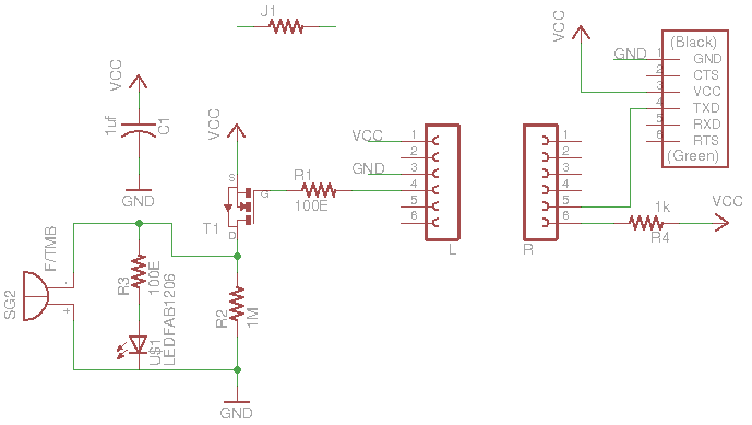
I've been using the EM18 which is the RFID module. The module comes in kind od DIP package and it is supposed to be mounted through holes. I've connected following pins to the EM18 module which are as follows.
- Vcc => 5V
- GND => Ground
- Sel => Pulled up using a 1k resistor
- TX => Connected to the satshakit Rx pin to read data
My satsha kit

This is the heart of Mudra project. This is the modifed version of the satshakit which will coordinate between the activities of the Mudra. My satshakit is having ports for directly connecting LCD keypad and RFID module. Most of them are using the FRC cables in 5x2 configuration. The FRC brings advantages as I documented earlier.
My satsha kit is powered by Atmega 328 chip from Atmel. This is the very popular chip amoung the Arduino community and can handle the kind of work I intended to do.
GSM Module
This is the circuit which I bought from market to connect my Mudra POS to the internet. This can take the advantage of GSM network to communicate to my Mudra server which can then record the results and store it. This circuit works with the 5V and has got status LEDs to convey the message about what circuit is doing?
The GSM module is connected to the satshakit using RS232 protocal whihc is two wire protocol. The modules talks to each other using the 9600 baud rate and with no parity and data size of 8-bit.
Making of Keypad
for my final project I wanted to have a keypad to interact with the device. The interaction includes the controlling interface and inputting the data as passwords and the amount to spend. Primarily I thought of making a keypad using through holes components, which will be easy to solder and I have good hold on through hole components.
So, I started designing the PCB for the same using EAGLE which is the nice and simple software, and I'm comfortable with the same. I designed my PCB as shown in the GIF attached.
While designing I came across the problem where I have to use the multiple layer PCB because of the matrix structure of the keypad. There are multiple columns and rows which I have to connect without shorting them. And using the jumpers(I mean 0 ohm resistor) in the EAGLE is bit tricky process.
The problem - Milling double sided PCB
I was unsure about the milling double side PCBs on Modela MDX20 machine. But I thought of give it a try to upgrade my skill-set. Unfortunately I milled the PCB with the error. The problem with the PCB was they layer on the to is not aligned with the bottom. As the result my PCB is complete waste.
Then I discovered the PCB which was the milled, I found that I adjusted the zero 5mm away. Gossh!
So, that day my lab hours are finished and I have to pack-up and go back home. During the journey I calculated the problems may associate with the though hole design. The problem I thought of are listed below:
- Mounting of the keypad will tricky, ans the base is not flat with THT components.
- Connection of top layer and the bottom layer will be time consuming as we cannot process via with conventional method.
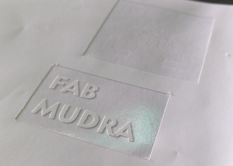
Vinyl Cutting
Demo
BOM
Note: I've generated for keypad as kokopelli doesn't allow me to do so.
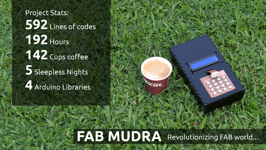
Project Stats
License
Copyright 2016 Yogesh R. Tamhane
Download Original Files
- modified_satshakit_cnc.zip
- CASE.cdr
- MudraStickers.cdr
- Arduino code, GUI on 16x2
- Clone my entire project from GitHub
Note: All CorelDraw files are designed are saved in the Corel 17 format
References and further reading
- Installing phpmyadmin on Ubuntu 16.04
- How credit card number work?
- PHP Insert Data Into MySQL
- Sending form data
- Check password from SQL table
- How to store passwords
- Count Number of rows in SQL table using PHP
- POST data without using HTML form
- HTTP POST request
- EM18 reading codes/code format
- Turn on PHP errors