Electronic Production
- Index
- Electronic Production
- Goal
- PCB Selection
- Preparation
- Grabbing the end-mills(tool)
- Using FAB Modules
- Bit Adjustments and Milling process
- Errors
- Board is milled
Goal
The goal of this week is to make a AVR programmer. Sounds great right? programmer is the circuit capable of writing(burning) the programs on to different micro-controllers. So, in this assignment I'll be milling the PCB and populating the board with SMD components.
PCB Selection
There are varieties of PCBs available in the market. Each and every other PCB is recommended for the different purpose. There are few grades we can name they are FR-1, FR-2 and so on till FR-4.
The more information about them I fetched from following links:
So, now when I was attending the pre-fabacademy lectures, we have discussed about the properties of the FR-1 materials and that it is very suitable for the milling machines like Modela MDX series. So, from the FAB inventory I picked one FR-1 board too mill the PCB.
Getting started
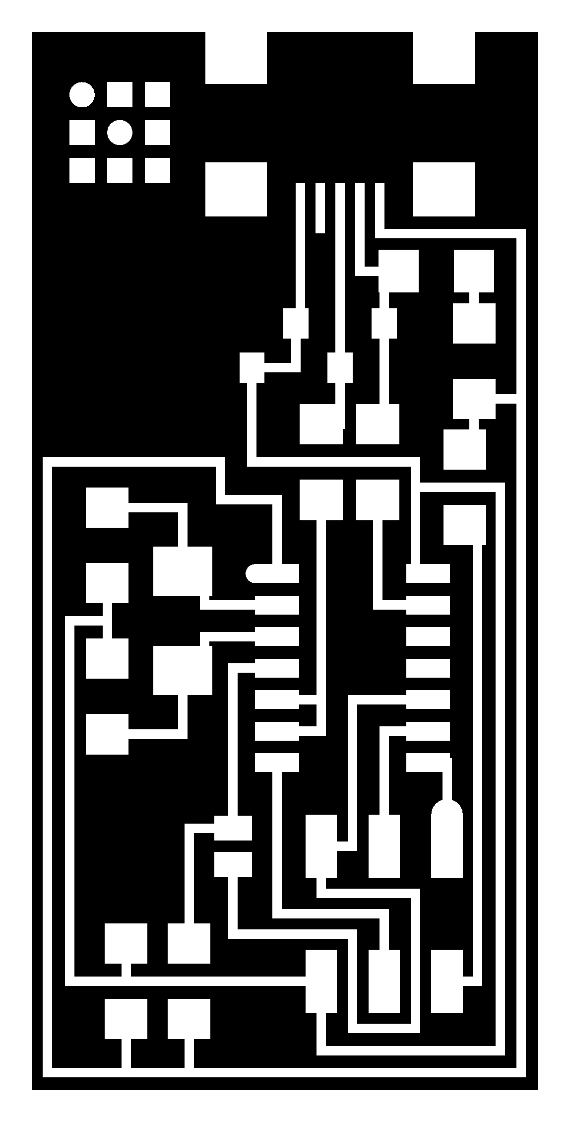
Once the FR-1 board is taken out for the milling the PCB design, but where's the design. So, from the FAB Academy 2016 class page for electronic production week I've downloaded the design. From here download the files, which are listed under hello.ISP.44 name. I've downloaded the three files and they are as follows.
- hello.ISP.44.traces.png - This file will be used to mill the traces
- hello.ISP.44.interior.png- This file is will be used to cut-out the board from the main PC
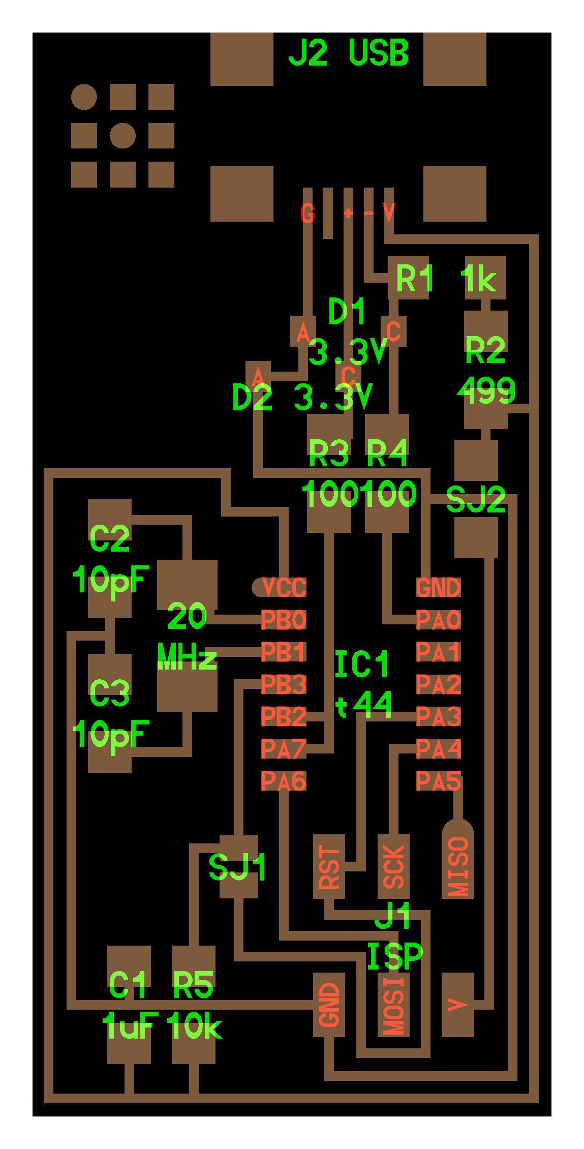
- hello.ISP.44.png - This is the file will help me to solder the components in right place
When we got the files on board, we can now start the FAB Modules which we have installed from the Supernode's Guide.
Preparation
When I heard about the term milling, to know more about it I searched it on Google, the robot replied me like,
Milling is the most common form of machining, a material removal process, which can create a variety of features on a part by cutting away the unwanted material. The milling process requires a milling machine, workpiece, fixture, and cutter.
Model MDX-20

Now I know that I'll be milling the board to make the PCB that means machine will be removing the excess. Yes, it's the subtractive manufacturing technique. So that I've to take care of the machine as will as the board. So, as per the Neil's word I to use an underlay board, which will be fitted directly on the metal surface of the Modela machine while the main target board I've to place on top of underlay. This arrangement helps to safeguard the bit as will as the metal platform.
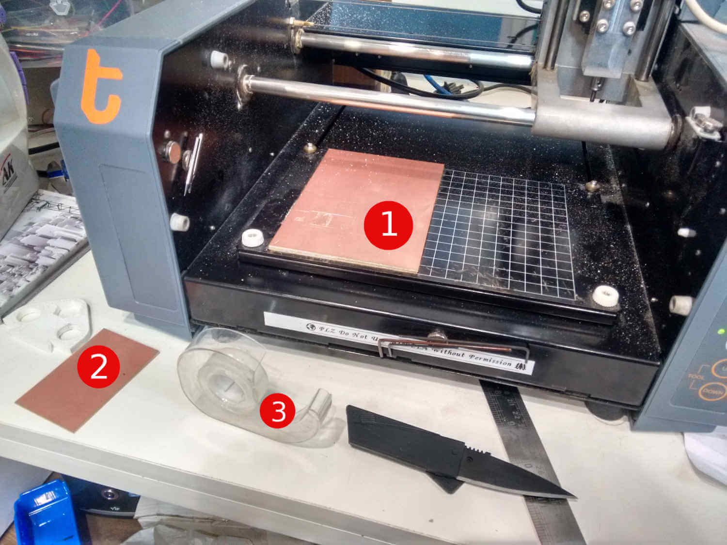
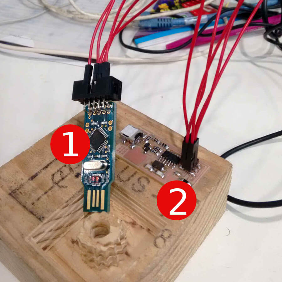
In the image above you can observe the numbers, each of them I'll be explaining in brief as follows.
- It's the underlay board which will safeguard the Modela MDX-20.
- It's the target board on which will be milling our circuit.
- Double sided tape which can be used to stick the target board to the surface of the underlay board.
Grabbing the end-mills (tools)
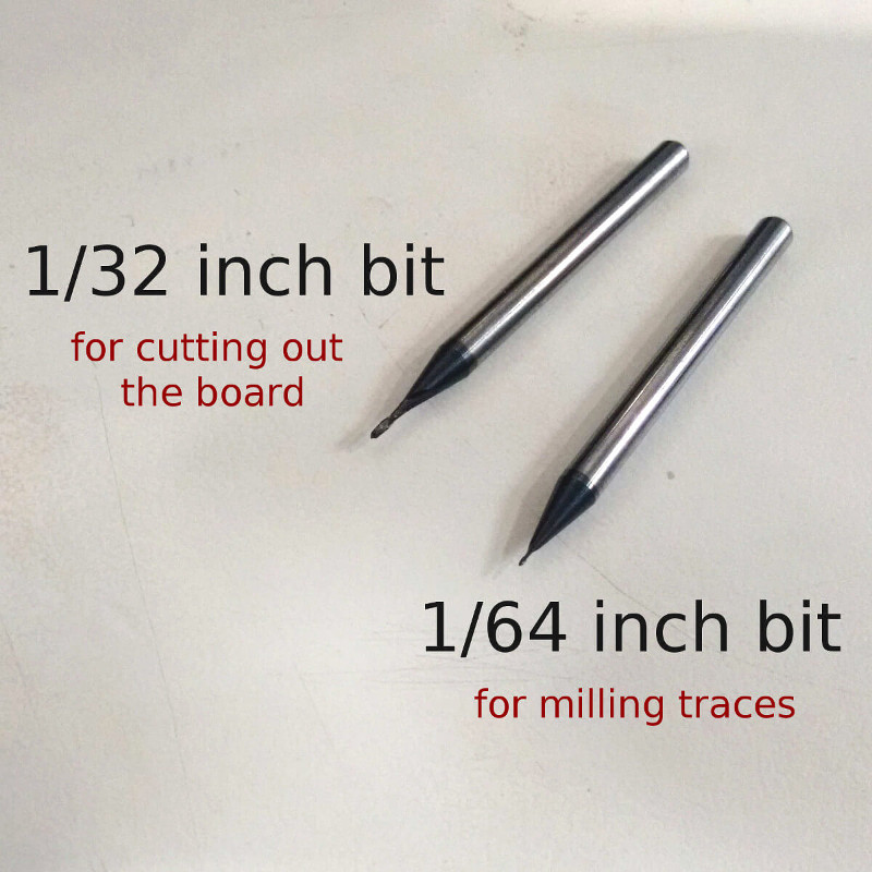
So, mill the trances I'll be using the 1/64 inch bit and 1/32 inch bit to cut the board.
Using FAB Modules
Once launched, we can open the PCB traces files to the FAB Module with the input file option and selecting .png format. And then selecting the output format for Roland Mill.
Bit Adjustments and Milling process
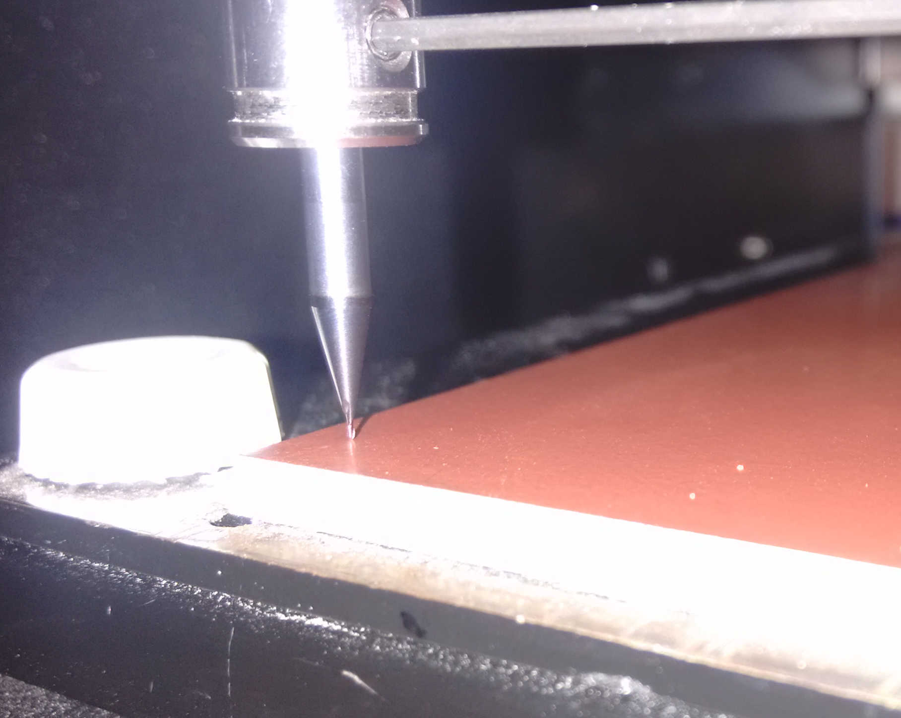
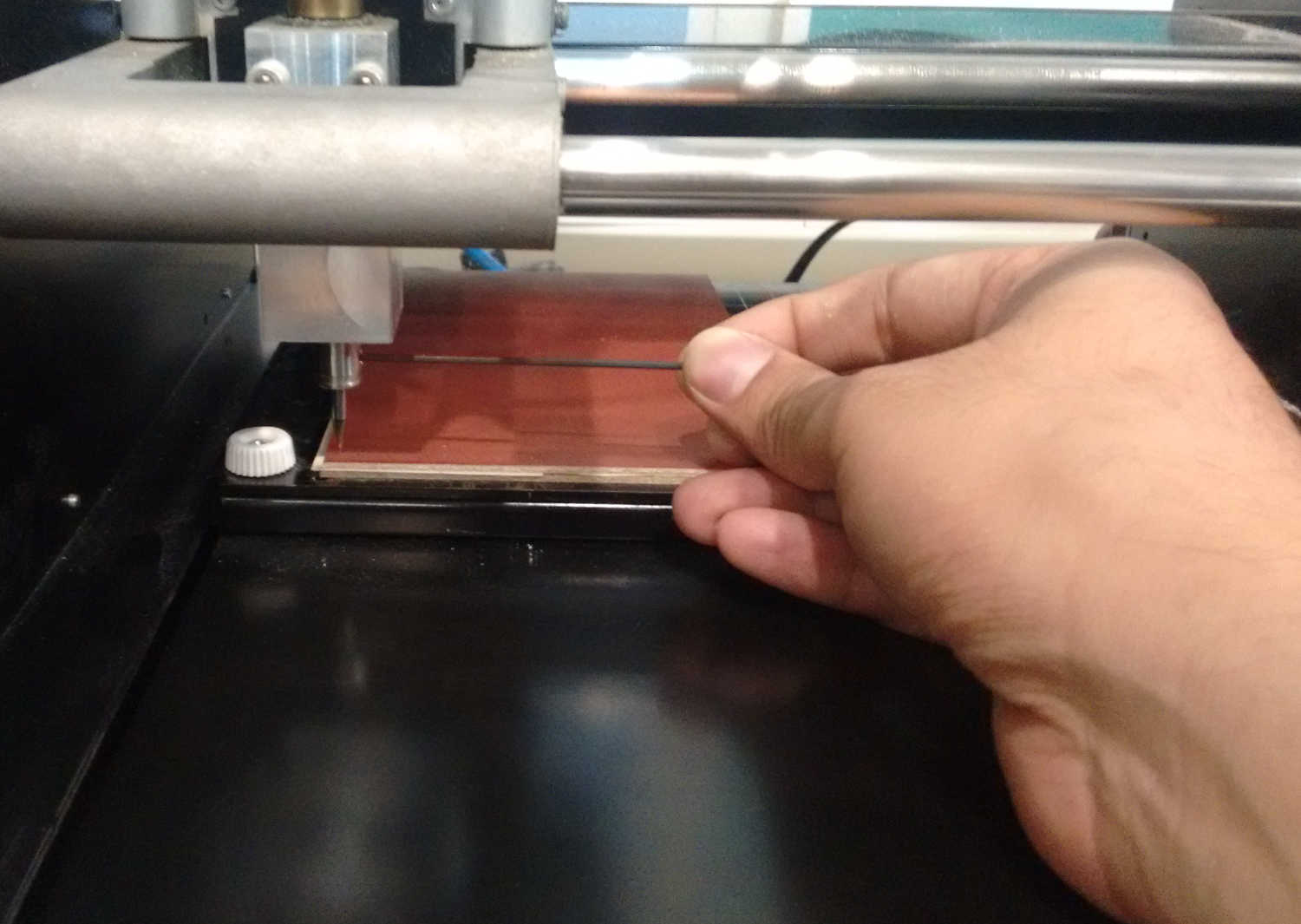
Adjusting the end-mill: end mill is supposed to be adjust exactly touching the PCB surface not piercing the PCB as shown in the figure.
While Modela was too busy with the Job - Milling Tracks the end mill(1/64 inch) rotates super fast and removes the top copper surface of the PCB which in results makes the tracks.
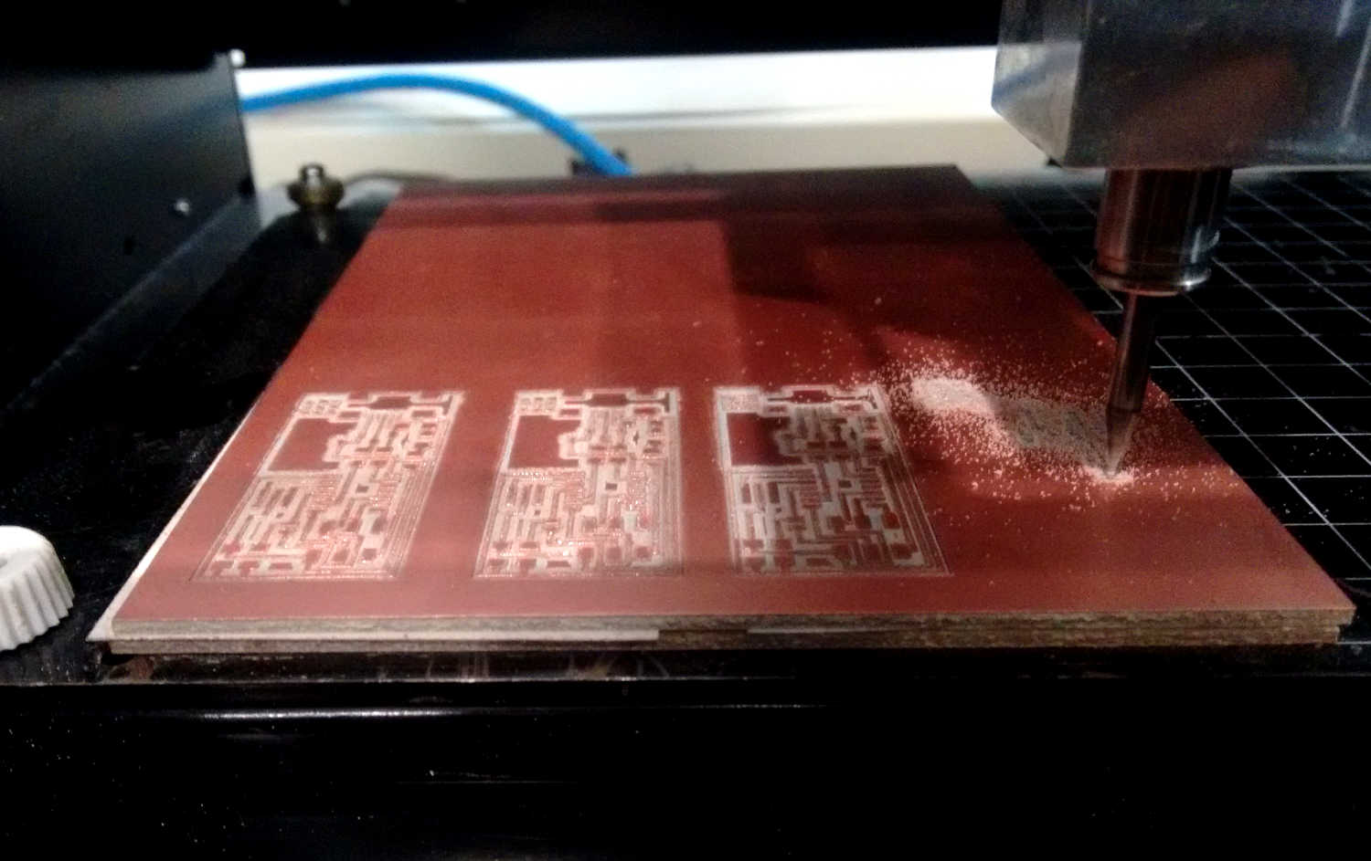
While Modela was busy with the cutting the board the end mill(1/32 inch) is used to cut the board. The machine doesn't cut the whole board at a stretch but it takes three consecutive rounds to pop-it out.
Board is milled!!

Now we have our the boards milled. Now, we can populate the board with the components. To pick the perfect board you have to check out the edges of the traces. If they are super sharp that means the board is perfectly milled. As you can see in the image above the board on extreme right hand is not the good because the edged are bit rough. The board on the extreme left hand side is the best as we have the very sharp trances all around the board.
Populating the board
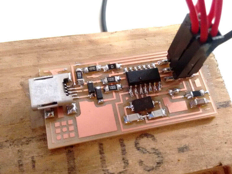
Final - Milled and Populated board
Programming the FABISP
- USBasp (programmer)
- FABISP (target board)
Testing the FabISP
To test the FABISP which I've managed to make I carried out following tests.
Primary Testing (Whether FABISP recognized by BOX?)
Very primary indication which is the best indication of whether the thing is working or not is to connect it with the computer and list out all the USB devices with the command line.
lsusb | grep usbtiny #command lists out all the peripherals connected via USB
Upon execution of the above command in the terminal I got the list of peripherals connected via USB port to my BOX and filtered out using the grep.
If terminal returns nothing it means that FABISP is not working correctly. If it returns a line with the device id and bus number it's an indication of you've got the FABISP working!
Secondary Testing
Yep, my primary test was successful and now I'll be moving further ahead for the secondary test.
Setup
For the secondary test I wanted to have another micro-controller board which I know that it's working so, I pulled out the Arduino board which I know that I was working and connected it to the FABISP using the jumper wires. The connection between the two were as follows.
| FABISP | Arduino Uno |
|---|---|
| MISO | MISO |
| MOSI | MOSI |
| SCK | SCK |
| GND | GND |
| VCC | VCC |
and power up the Arduino using it's own power cable.
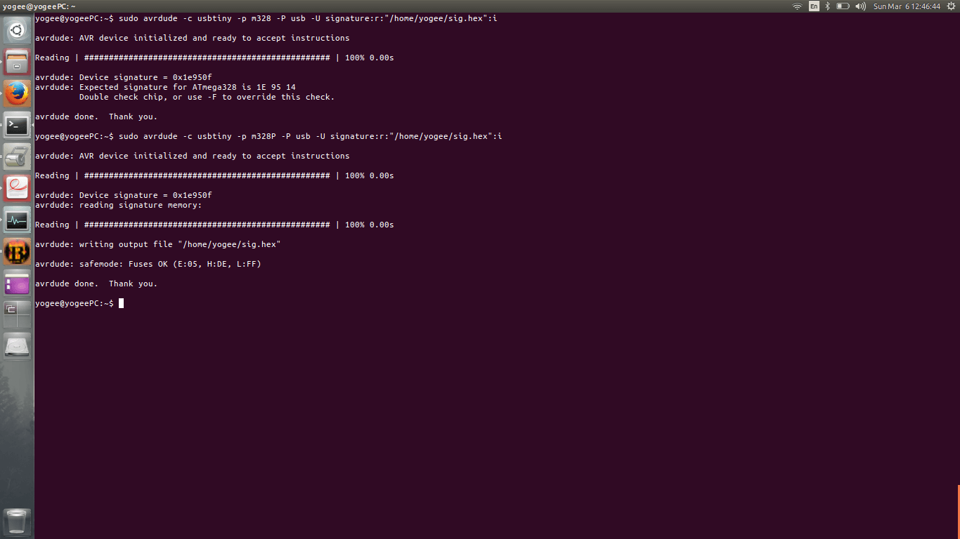
Then I connected my FABISP to the BOX using mini USB cable and issued the command to read out the fuse bits of the micro-controller present on the Arduino board (Atmega 328).
Command is as follows:
sudo avrdude -c usbtiny -p m328 -P usb -U signature:r:"home/yogee/signature.hex":i
How do I?
- How to implement RTOS on embedded devices such as Atmega series controller?
Errors
Board is not getting milled correctly
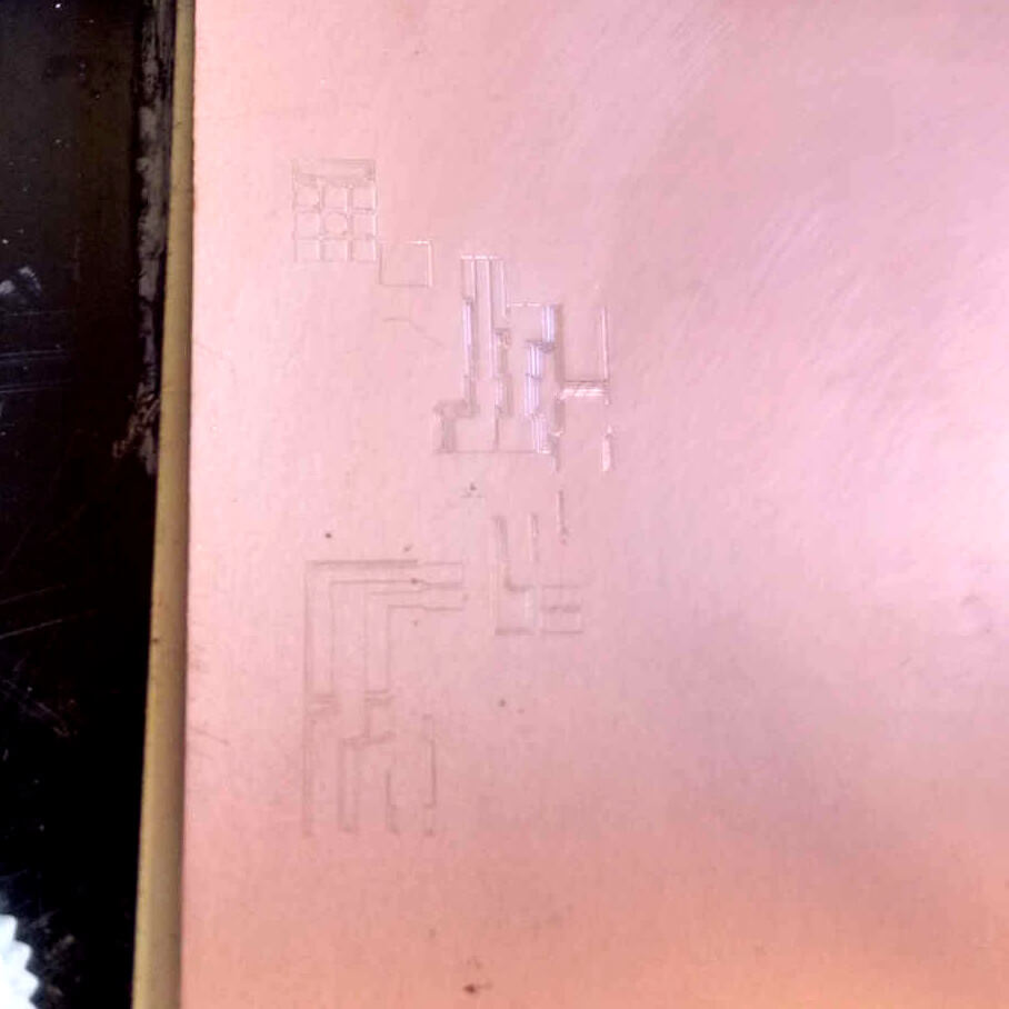
Not adjusting the end mill correctly. The result is shown in the picture. The end mill is not able to rip-up the copper out as much as we want. The milling is very superficial.
Solution
The solution for this problem I found out is to have the end mill correctly attached to cuffs of Modela. For the proper arrangement of the bit on the surface of board I used the technique of loosening bit little to make it fall on the PCB once done, then we can grab the Allen key to tighten the cuff screws. This technique is worked for me like charm.
Board is not enough stable on helping hands to solder the components
The problem with holding the PCB with the soldering soldering / helping hands / third hand is that, the one we have in our lab is it just slides out even on the application little force.
Solution
My batch-mate Akshay Goharkar found the solution which is sticking the PCB on the piece of wood which you can see in above pictures.