3D CAD designing
- Index
- Tinker CAD
- How to Download and Install TinkerCAD?
- Desing planning
- Rough Sketch
- Open the TinkerCAD and get started
- Final Output
- STL Files
- Antimony
TinkerCAD
How to Download and Install TinkerCAD?
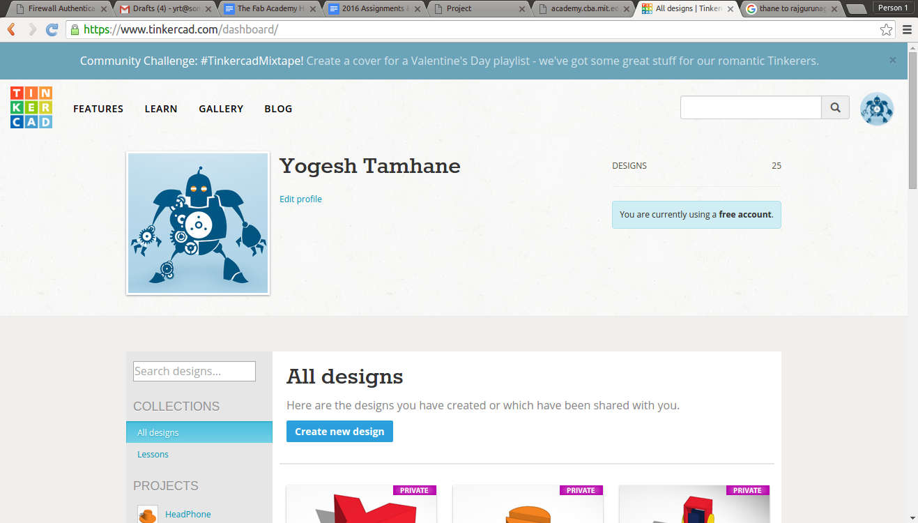
When you select the software one thing which comes to our mind is how to Download and Install the same, right? But in case of Tinker CAD it is not true. This is completely web-based software. So, all you need to do is to open up their website, sign-up and you are ready to fly.

once you have the sign-up for TinkerCAD you can sign-in to the profile and there you can see all of your projects and files.
Desgin planning
Step 1: Data gathering
Once you have imagined the your final project and the model for the same. now I have to gather the vital parameters and the components that I'll be putting into the POS.
By referring my project page I can listout the materials that I'll be using those are as follows,
- POS - Point of sale terminal
- Micro-controller (Atmega 168/328)
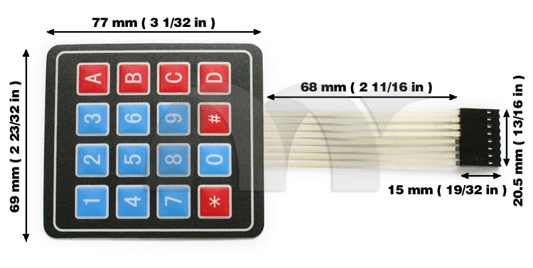
- Keypad (an input device)
- Screen (a ouput device)
- Card Reader
- LED indicators
- Communication Device (GSM Modem)
- Battery
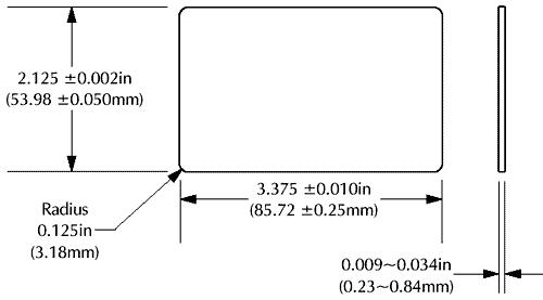
- RFID/NFC cards
Now I'll be collecting the dimensions of all the components. Belo you can find all of them,
Micro-controller

The Trick!
As I'm newbie to FabAcademy and I don't have the fabkit with me then how do I get the dimensions of the board? The trick is, I know about the FAB's open source culture, that means I can get soucre of fabkit very easily. I found the source of fabkit here then I downloaded the board file, now I have the board file but no EAGLE installed till date with which I can open the file, then I got back to Google to ask fot online .brd viewer and Google said goto 3D brd viewer upload your file and there you can observer the demisoins.
Mechanical drawing of other components
The mechanical drawings can be found through Google.

Now, I've to check out in the market about the current commercially available POS system, which will guide me for design and the rough dimensions.

Rough sketches
Very first step of making any CAD model is to visualize your plans on piece of paper. This help the one to speedup the process of designing.
What I feel is, all the CAD tools are drafting tools, they exists to make your designs presentable and help you further to evaluate them. Designer is you and use your brain to forecast the design problems that may come during the drafting. Once you make sketch and anticipated the problems go ahead and open the CAD tools, otherwise keep them aside. This is what the key I found out with my experiences.
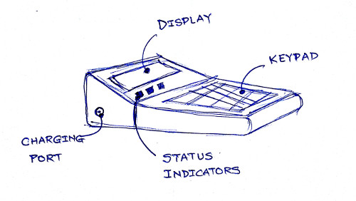
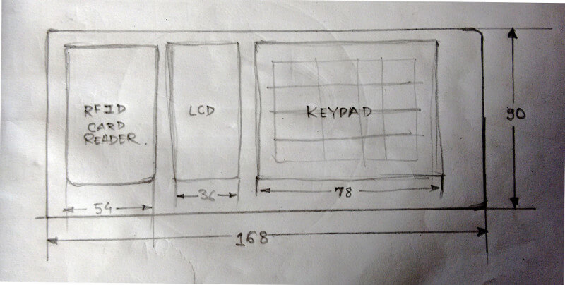
Below you can find the top view of the POS that I'm planning to build. The sketch is made to checkout the space allocation by each of the components. This helped me a lot to finalize the outer dimensions of the POS terminal.
In the image above you can see the Mudra POS terminal which I'm going to build for my final project.
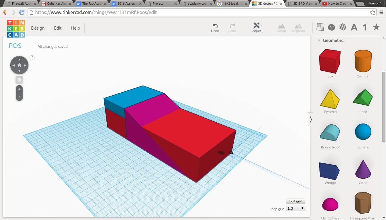
Open the TinkerCAD and get started
Step 1:

Step 2:

Step 3:
Step 4:

Step 5:

Step 6:
Step 7:
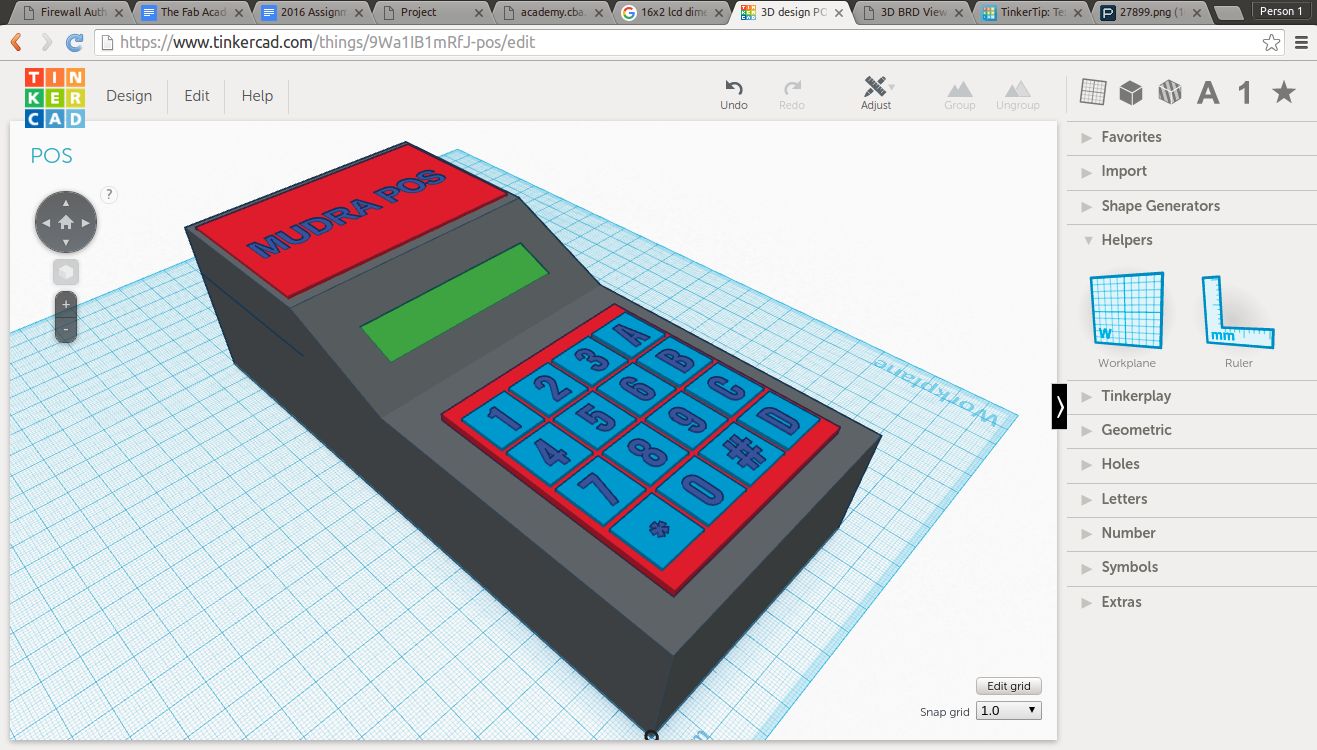
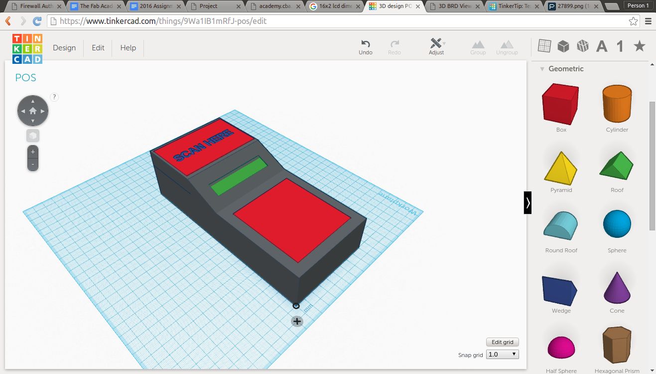
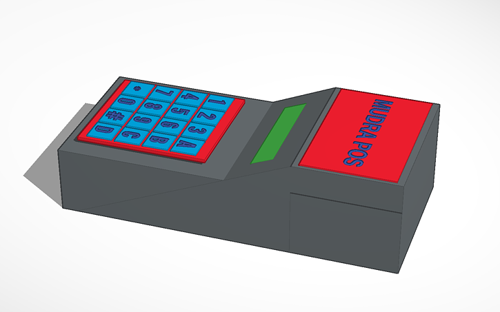
Final Output
Donwload my TinkerCAD file
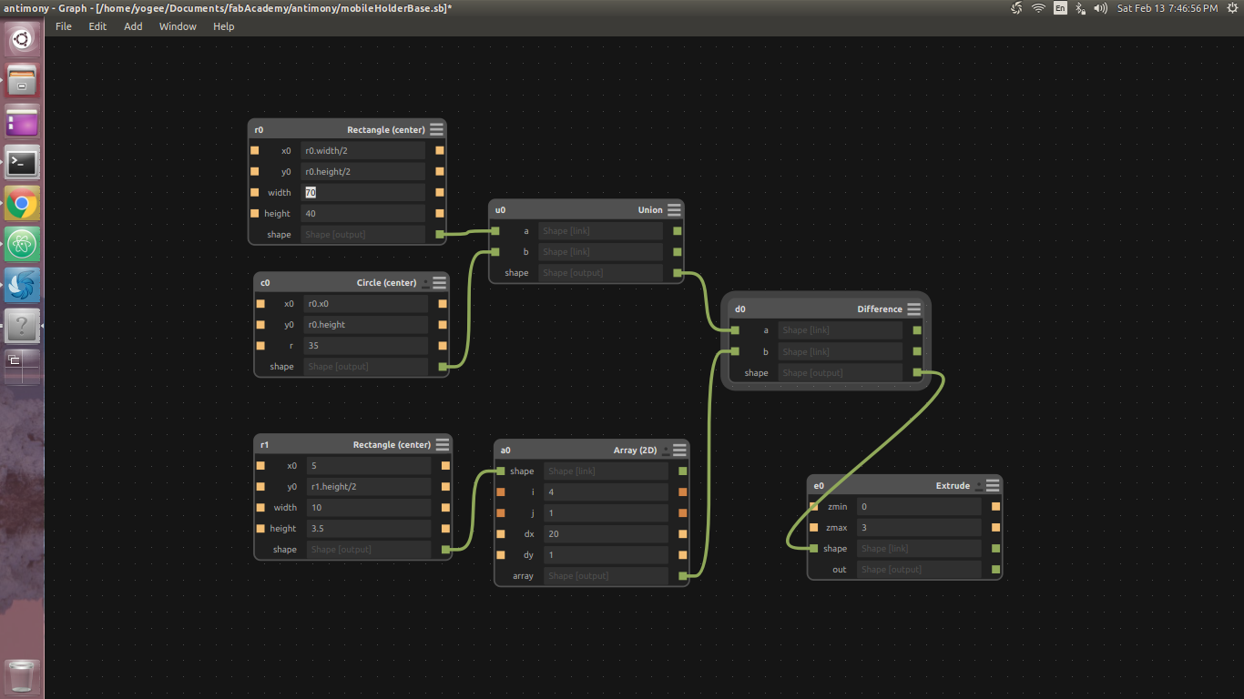
Antimony
Antimony is the parametric 3D designing software built by Matthew Keeter. Which is open source the repositories available for tweaking at github Antimony. This software is the still in development stage and stables and nightly build gets posted regularly. Antimony is written in Python and it's a really powerful 3D designing tool. The feature of the this tool is having a kind of data flow structure in your designs. When you open Antimony you can observe the two windows one of them is known as Graph window and another is known as View window.
Graph window is the one which shows you the blokes of primitives and functions which in results creates th whole model.
View window is the windows which actually shows your 3D model. This renders the blocks in real 3D world, which you can rotate and view the entire object by zooming in or out.
Installation of Antimony
This is actually a tricky process, because we have to clone the entire repository and build it to install and the instruction mentioned on the source is based on older version of QT, now it has got updates which actually changes the directory structure. Following procedure I did for installing the Antimony.
Here's Double Check!
The problem with the instructions provided on the github is old and QT is updated with the latest version. So, to you just have to make the changes while actually generating the make file.
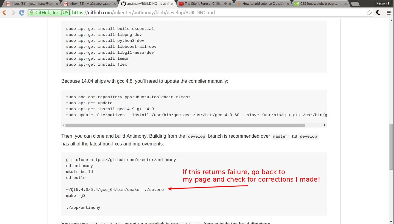
in above image you have to check out for your installation directory of QT and change the things accordingly. So, in my case it is.

/home/yogee/Qt5.5.1/5.5/gcc_64/bin/qmake ../sb.pro
and then you can proceed with the instructions provided on the github to build.
Making a first model with Antimony
Now, let's open up the Antimony by entering the command antimony in terminal. You will see such windows on your screen.

As we have discussed earlier about Graph window and View window
Now, let's dive into the actual destining part.
Step 1:
Rough sketch and deciding dimensions
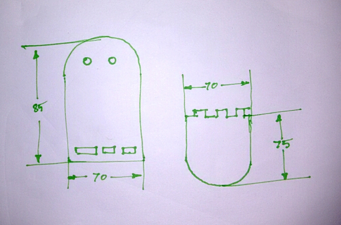
We have to design two objects as shown in the figure. The object which is on the left hand side will hold the pins of wall socket and other object winch is on right hand side will hold the mobile phone.
Step 2:
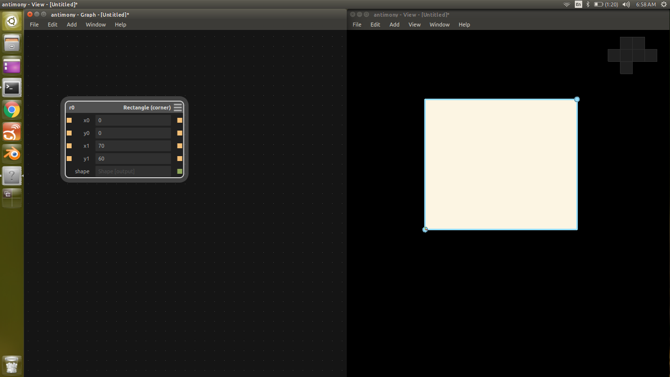
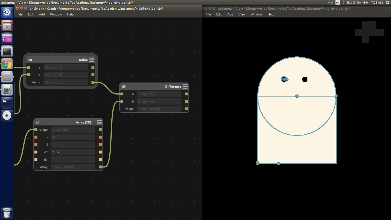
Now, let's open Antimony and start drawing the objects.
Step 3:
Step 4:
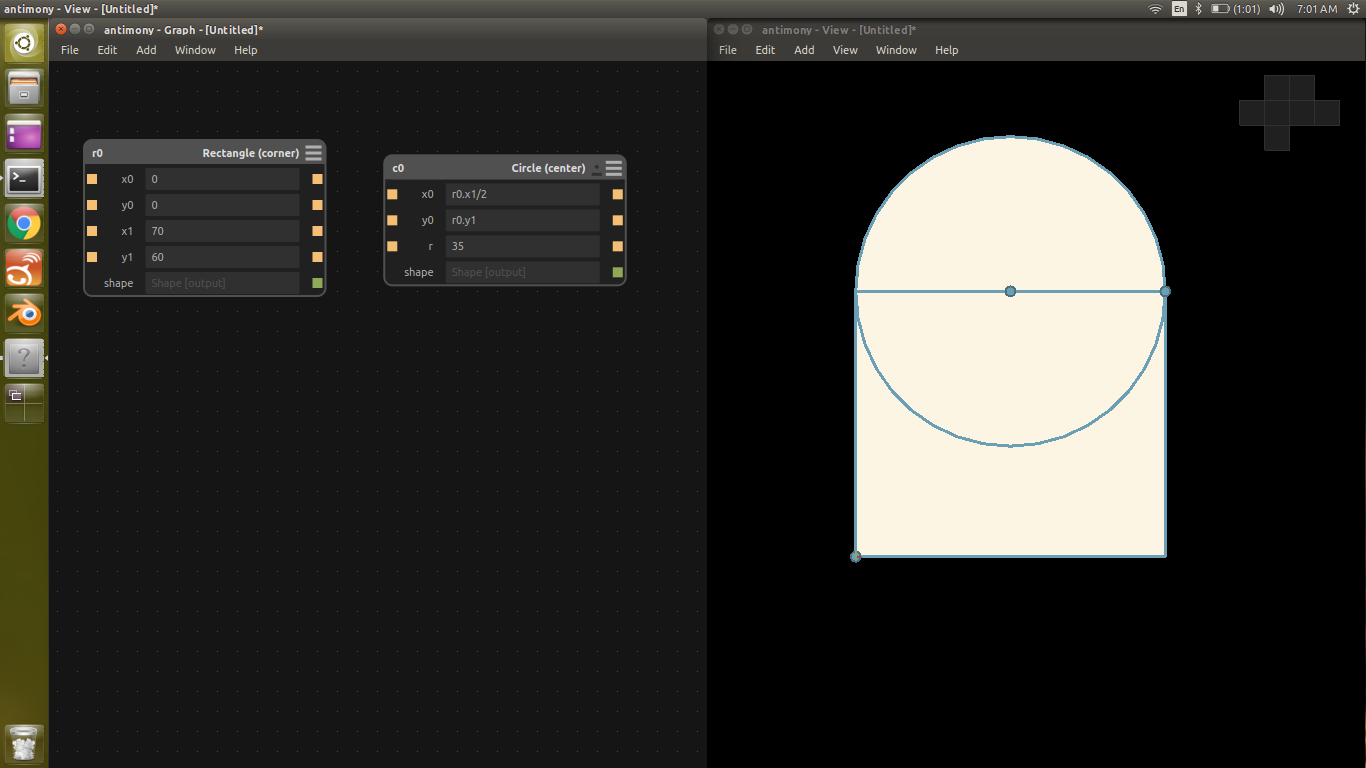
Step 5:
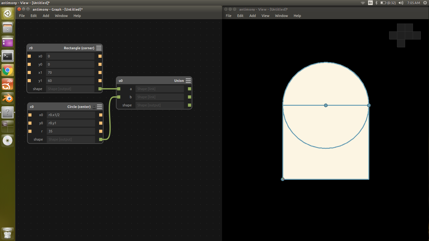
Step 6:
Step 7:
Step 8:

Step 9:
Step 10:
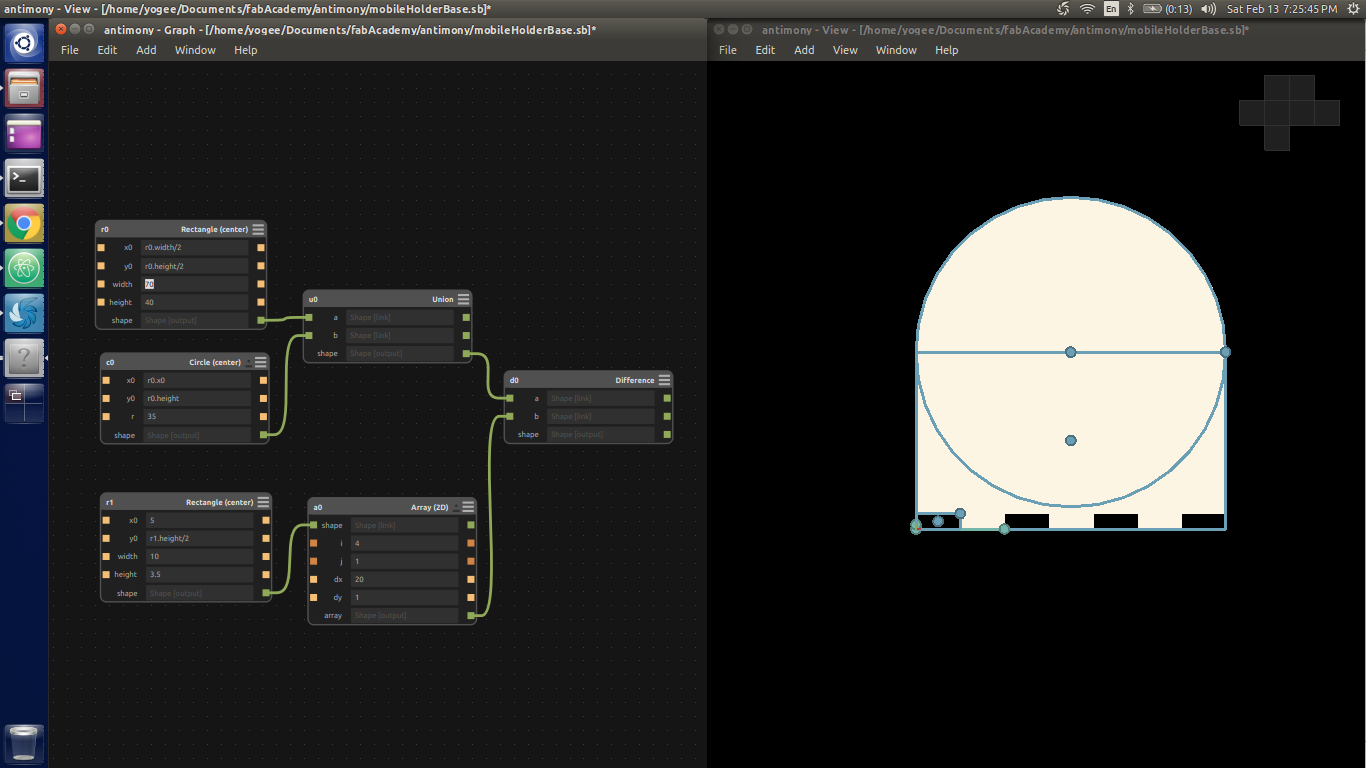
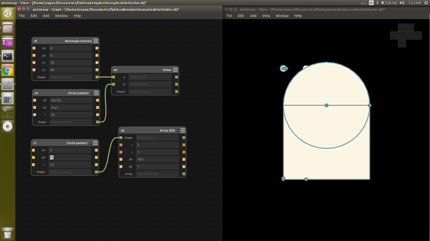
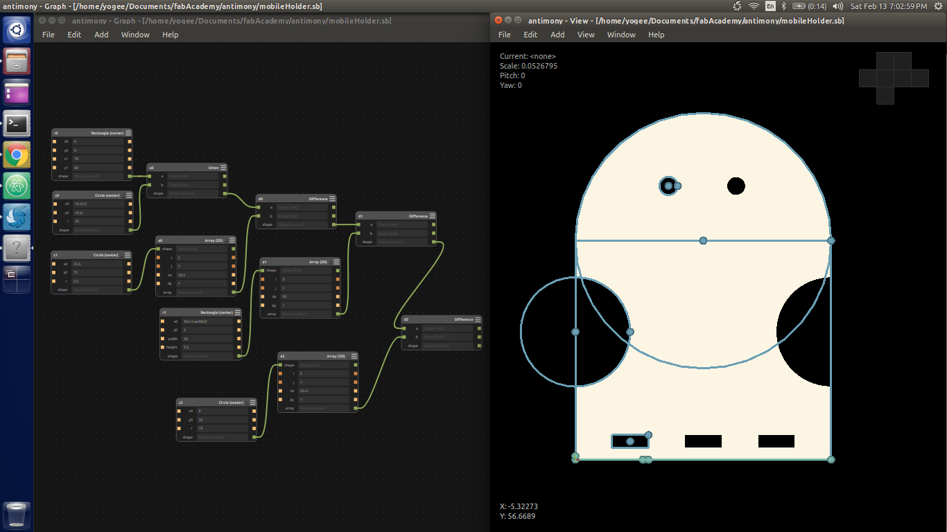
The Final versions of CAD is as follows
Graph for object 1 with it's 3D view


Graph for object 2 with it's 3D view