Assignment 15: Networking and Communications
During this week I'll be working on networking part. When I came across the term networking I Googled it to get the very precise definition of the term, according to TechTarget:
In information technology, networking is the construction, design, and use of a network, including the physical (cabling, hub, bridge, switch, router, and so forth), the selection and use of telecommunication protocol and computer software for using and managing the network, and the establishment of operation policies and procedures related to the network.
which I feel is the perfect and well elaborated definition for the term networking.
Goal 1
This time I'll try to communicate between the two boards. Which I've made in previous assignments. I'll be using the following boards to achieve the goal.
- LCD Board -> Attiny44 with 16x2 LCD interface
- Button attiny45 -> Attiny45 with Button
Setup and Experiment
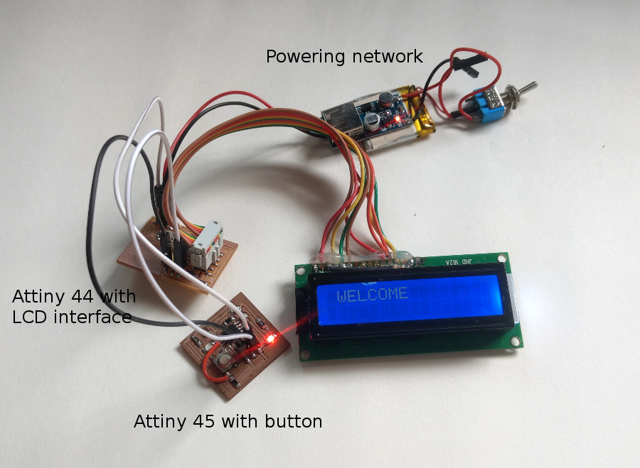
For the first goal to accomplish I'll be using the LCD board which will control the LCD function and can talk to the other boards using RS232 protocol. In picture the Attiny45 board which will sends the message to the LCD board, when this message is received by the attiny44 it will display the message that key is pressed.
Attiny45 is sending the character 'a' every time when I press the button, when the character 'a' is transmitted over the serial protocol the attiny44 reads the character and then it displays the message "Key Pressed" for 1 second and clears the LCD screen ad waits for another keypress to receive.
Protocols that I've used
- RS-232 Serial protocol
- Baud Rate: 4800
- Parity : None
- Data size : 8-bit
Goal 2
My final project is to implement the local currency, which includes the integral part of networking. That means I have to send and receive the messages to and from the server. For that I'll be using the SIM300 which is the GSM modules which can take SIM card in and can access the GSM network. For this week I'll be making the system to send data to the remote server using the my board which hosts the Atmega328.
This week I'll writing a code which can send/submit a hard-coded data to my server. Code for the same is attached below.
Block Diagram
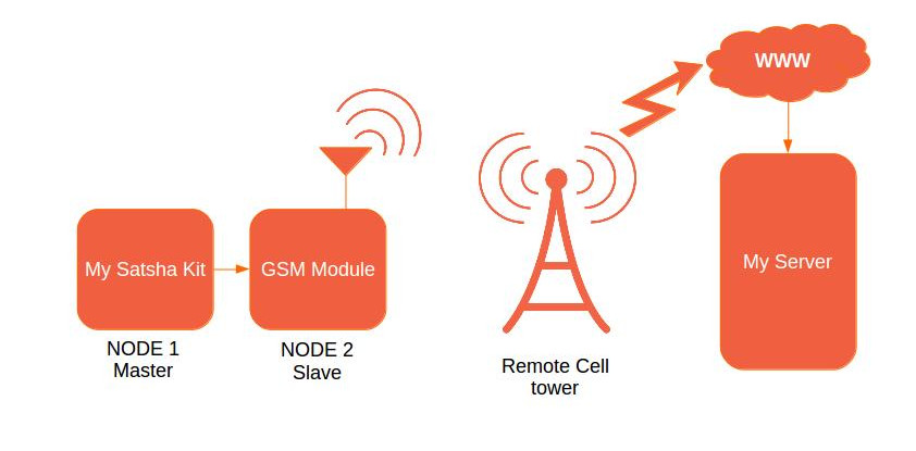
The block diagram here showing the setup I did for my networking assignment. In this week I'll be trying to communicate between the internet and my satsha kit. Here I took the following components and connected them together to make a simple network.
- Satsha kit
- GSM Module
Setup
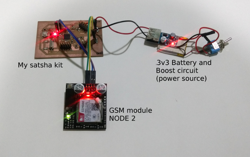
Here shown is my setup which can communicate with my server. Here I've tested the circuit using the library and how I did is I'll be mentioning in following document. After testing my circuit with sample code present in the library I'll be modifying the code which will suit my needs.
What is setup will do?Whenever I reset the micro-controller i.e. satsha kit using the reset switch, the code will generate the POST packet. The POST data packet is sent the the SIM800 IC which will take the necessary action with the data as per the AT commands given by stasha kit.
Get started

The picture shown besides here is of GSM modules which hold the SIM card at hear and access the GSM network. This modules the features the SIM800 IC which can communicate via RS-232 interface with the host micro-controller. SIM800 is the chip manufactured by SIMCom, this is capable of accessing GSM and GPRS service from the telecom service provider.
These board has got following pinout to connect to my satshakit.
| GSM Module Pins | Connected on Satshakit |
|---|---|
| Vcc | Vcc |
| GND | GND |
| RX | PD2 |
| TX | PD3 |
Step 1: Connect the GSM module to the stasha kit.
I connected all four pins to the satshakit using the jumper wires. As soon as you provide power to the satsha kit the led present at the GSM modules lit up. This indicated the power status is ohkay. To activate the communication with the SIM card module has got the button which user has to press for 3 seconds to start SIM800's talk to SIM cards.
Connection of communication pins i.e. RX and TX pins are really very necessary and those pins should be connected properly to make the satshakit talk to GSM module. If satshakit is not able to talk to the GSM module then it is very obvious that the communications pins are not connected properly.
Printing mistake present on the GSM module
Yes there's printing mistake is with the top silk layer of the GSM module. There I found both the communication pins are marked as the RX. There's no indication of the TX pin. So, I started referring the handout content which I got with the package, there manufacturer have mentioned the error. According to sheet, second RX pin is actually TX pin.
Step 2: Writing first code with the Arduino IDE
This module is very similar to Adafruit FONA which is also one of the popular GSM module. So, we can directly use the library written for FONA module. Please find the download location of the library in the references section.
I downloaded and installed the library as per the instruction given on the page. Very first test we have to do is to go ahead and burn the FONAtest example from the library and setup is ready to test. If this test code is not able to recognize the module then it's probably the issue of wiring. Try to following things to solve your problem.
- Swap RX-TX pins
- Make sure that bootup LED is blinking
The FONAtest code is written to test all the features availble with module. As manufacturer of this module is tried to copy the hardware architecture from the FONA module itself but some features are altered but we can able to acceess functions like GPRS, call, SMS without any problem.
Step 3: Try connecting GPRS
When you have stable network to your device you can get connected to internet using the GPRS signals.
I followed this method to test the Internet connectivity.
- Burn FONAtest sketch
- Turn on the Module and wait for LED to blink with lower frequency almost around 1Hz
- Open serial terminal
- Press 'G' to enable GPRS
- Press 'w' to visit website, then when prompted enter the website address e.g. www.google.com
- If the request went successful then the it will return the whole page in plain text format on your terminal
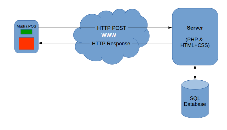
Step 4: POST some data
POST is very popular method around the web standards. Which depicts the form of sending the information to server in contrast with GET request. Major difference is that POST request generate HTTP package which can be sent over the network to communicate, which is not the case with GET request. GET request passes the parameters in the URL itself which makes the data visible to end user. On top of that GET request can be bookmarked, as it is just a long URL.
Therefore using the GET request is not justified in my case as I have to send user credentials and account details to the server.
Primarily test the service you can use the requestbin which is really good point to start testing with POST request. This web service allows me to post the data with any type of header and different encoding method and as I make the request it throws back the same data that I have requested. This helped me a lot during debugging process.
Make sure that
- have Both NL and CR for the serial monitor of Arduino.
- status LED is blinking
- Baudrate is set to 115200
Permission denied for /dev/ttyUSB0, that's because I 'm not able to send or receive signal data on Arduino serial monitor
This is the common problem with the linux BOXes. What happens it the the user which is running Arduino IDE is not allowed to access the serial terminal. Running following command solved my problem.
sudo chmod 666 /dev/ttyUSBO
Download Original files
- networkRx.zip
- networkTx.zip
- POSTtest.zip
- lcdTiny.zip
- satshakit_cnc.zip
Goal 1 Files
Goal 2 Files
PCB Files