Output devices are the things which presents the data. General example of the output devices are printers, screens, LEDs, motors etc.
Goal
In this week I've decided to make a circuit which will allow me to reduce the wire mess while using the 16x2 character LCD. LCD has got few control inputs and few data lines which all together makes LCD to show up some or the other characters.
My plan is to make a circuit using attiny44 which will connect the LCD in parallel mode and will provide the serial interface to send data to display it on LCD.
Planning
In Attiny 44 I've budgeted the pins as follows.
| Attiny 44 Pins | Used for |
|---|---|
| PA0 to PA5 | LCD data and control signals |
| PB2 and PB3 | Communication with host |


While I was going to through this week (output device), I found the board which Prof.Neil using for the driving the LCD. To cut down the lead time I've decided to modify the board which he has and modify it according to my needs.
Designing
Step 1: Download the .cad file
I downloaded the board from which Prof.Neil has made for the output devices, the board which drives the LCD.
I found out the board on this page, which is the class page for output devices week. On that page find hello.LCD.44.cad, right click on it and save it as .cad file. As this file is generated using the kokopelli I'll be using Kokopelli to edit the same. Editing in Kokopelli doesn't take given that you should know what you want to connect precisely.
Step 2: Open it using Kokopelli
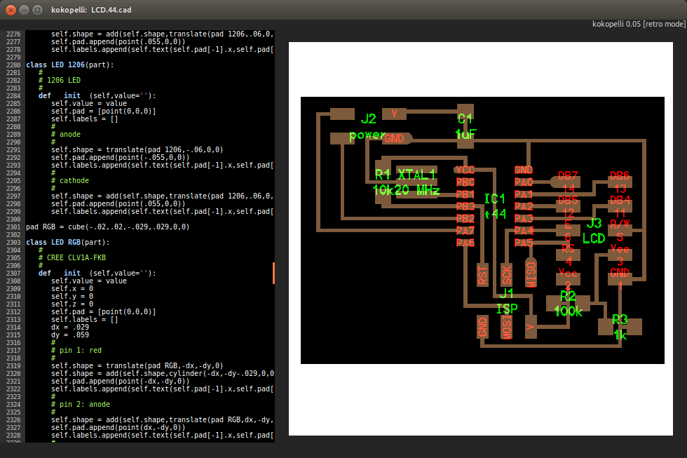
As you can see the picture attached this is the board written by Prof.Neil. Which doesn't have connection for the external host interface. My intention is to make the serial to parallel converter for LCD, to read serial data sent by the device I've to get a separate port from host controller can send the data in.
For communication with the host I've decided to use the RS-232 protocol which is available in most of the micro-controllers and easy to implement in embedded coding if micro-controller doesn't have hardware USART port.
Step 3: Here's the edited version
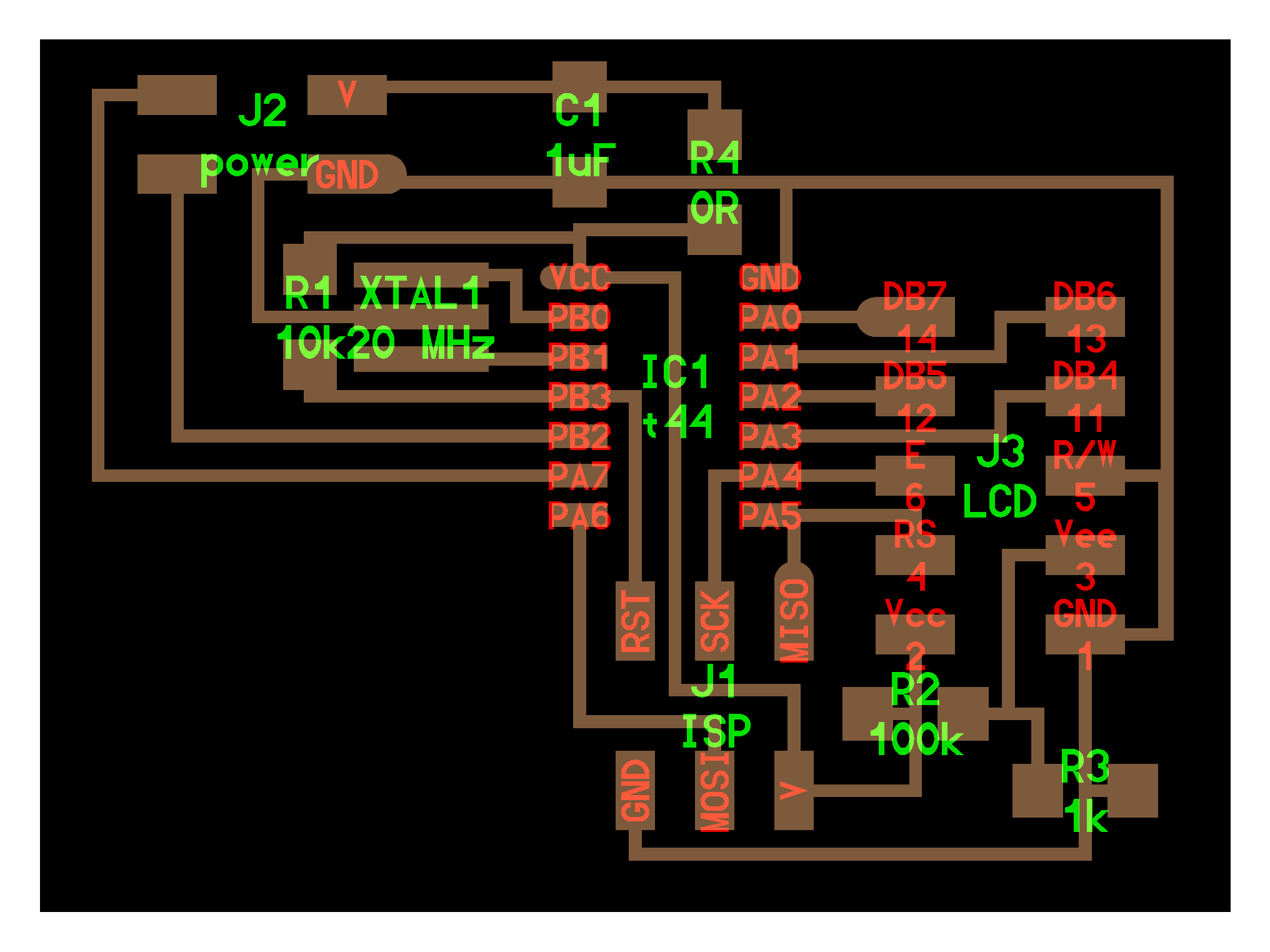
- Added two extra pins for host communication PB2 and PA7
- Added jumper to avoid cross-over of traces
- Re-routed the wire of ground signal from J3 to J2
Few things I forgot to add
- Power on LED
- extra LED to quickly test board using Blinky!
Step 4: First test - A smoke test!
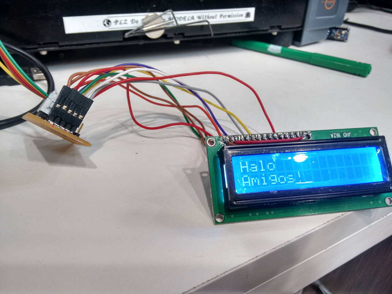
Here I attached the board to the LCD using bunch of jumper cables. Believe me this is the nasty job. This LCD circuit uses 6 pins to get data from micro-controller so, even if one of the wire from the bunch is not properly connected it takes down entire communication with LCD, as a result LCD doesn't even shows blocks/pixels.
Later I made the cable 10 pin FRC cable which is very simple to connect and easy to troubleshoot. To test the circuit I've used the code given on the this week's assignment page. I downloaded it, open it into the gedit and burnt it using the following command.
make program-usbtiny
Before all remember to install avrdude and goto the folder with command line where you have downloaded source file and make file.
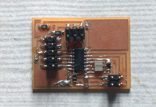
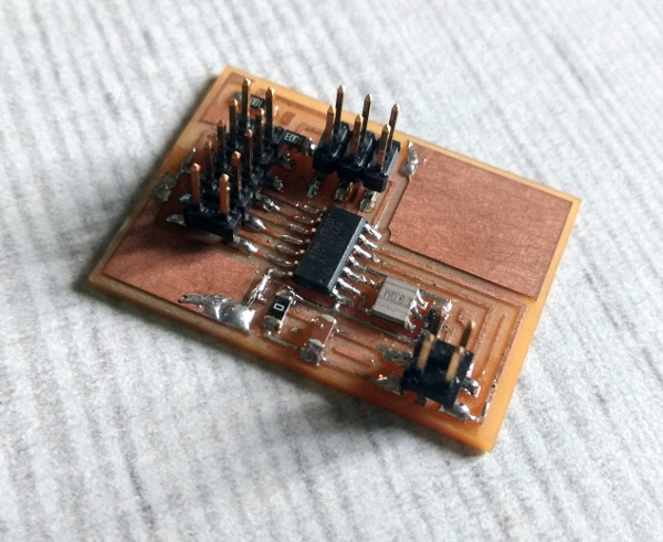
Heroshot