Input Devices
An input device is a device/equipment/sensor used to provide data and control signals to the micro-controller i.e. main processing unit and can able to read the information sent by the these input devices. Examples of input devices can be as simple as a switch and keyboards and as complex as mouse, scanners, cameras and joysticks and sensor which can sense temperature, acceleration and other real world parameters.
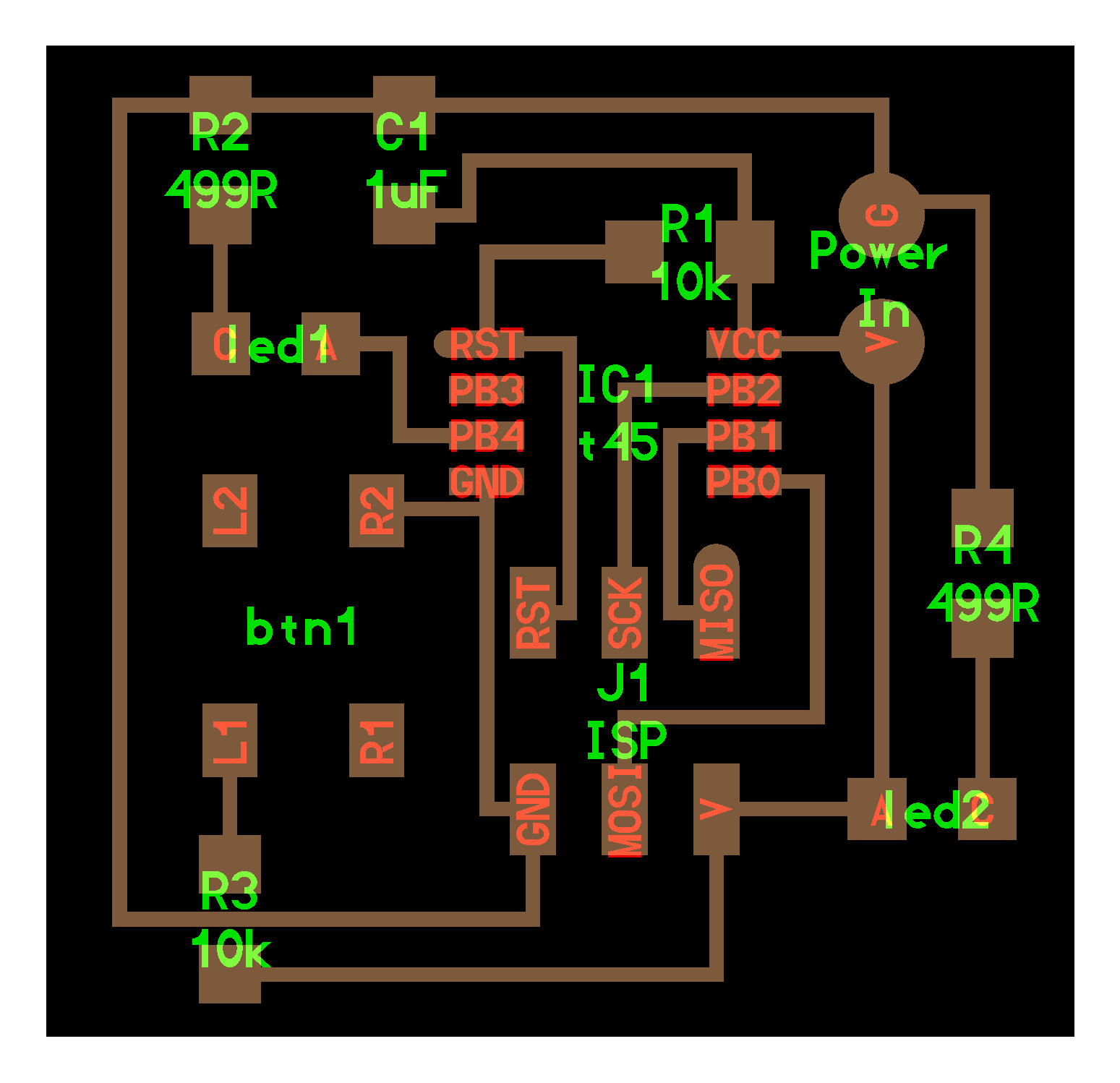
Making of Satshakit
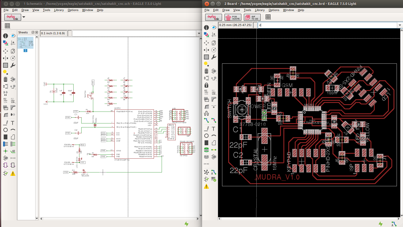
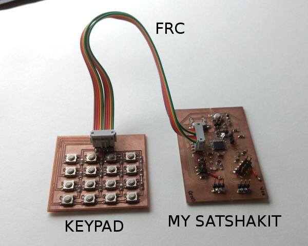
I downloaded the satshakit files from the source. I downloaded the files from the git hub for satshakit here from github. I've rearranged components and added the 5x2 header which is very handy to use for interfacing my keypad and LCD which is aimed at my final project.
Now in this week I'll be using those same connector with jumper wires to hookup the sensor to my satshakit.
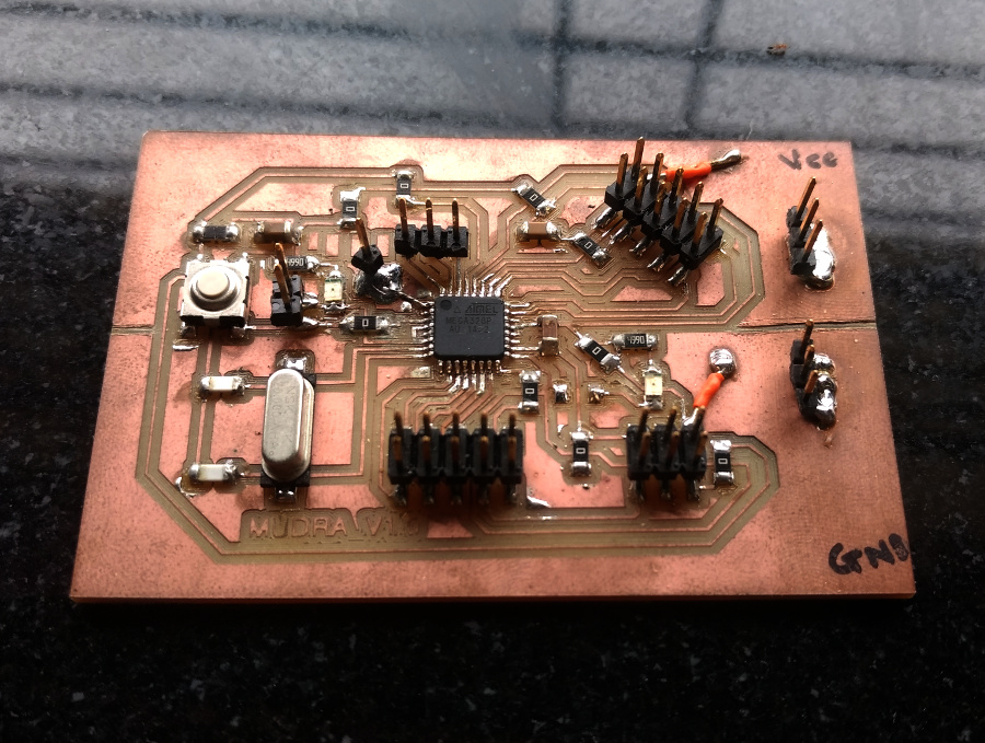
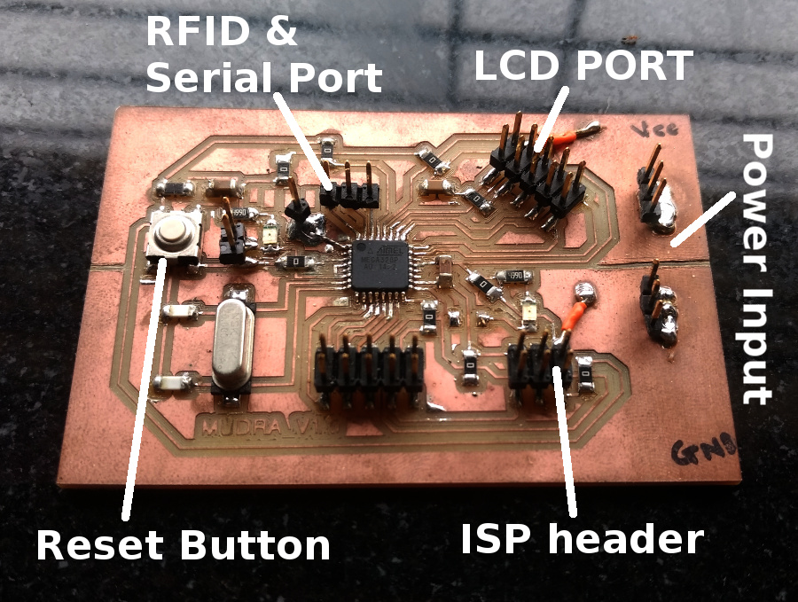
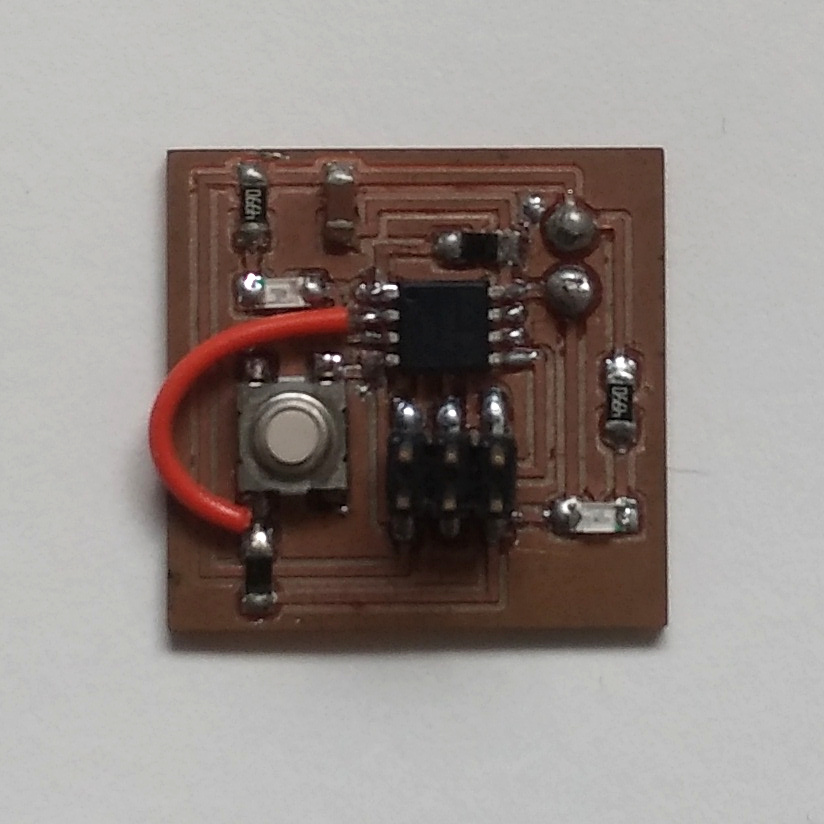
Heroshot Satshakit
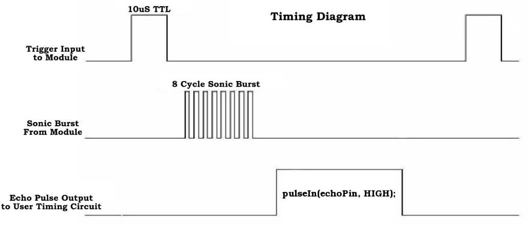
Ultrasonic Sensor (HC-SR04) - Analog Mode
Select the pulse mode by removing the shunt from the operating mode selection jumper. Connect the Trig/TX pin to a digital output on your microcontroller and the Echo/RX pin to a digital input. To obtain a distance measurement, set the Trig/TX pin high for at least 50 microseconds then set it low to trigger the measurement. The module will output a high pulse on the Echo/RX line with a width that corresponds to the distance measured. Use your microcontroller to measure the pulse width using microseconds. Use the following formula to calculate the distance:
Distance in cm = PulseWidth / 58

Connections
| Arduino Pin | SR04 Pin |
| 5V | Vcc |
| GND | GND |
| D4 | Trig |
| D6 | Echo |
Ultrasonic Sensor (HC-SR04) - Digital Mode
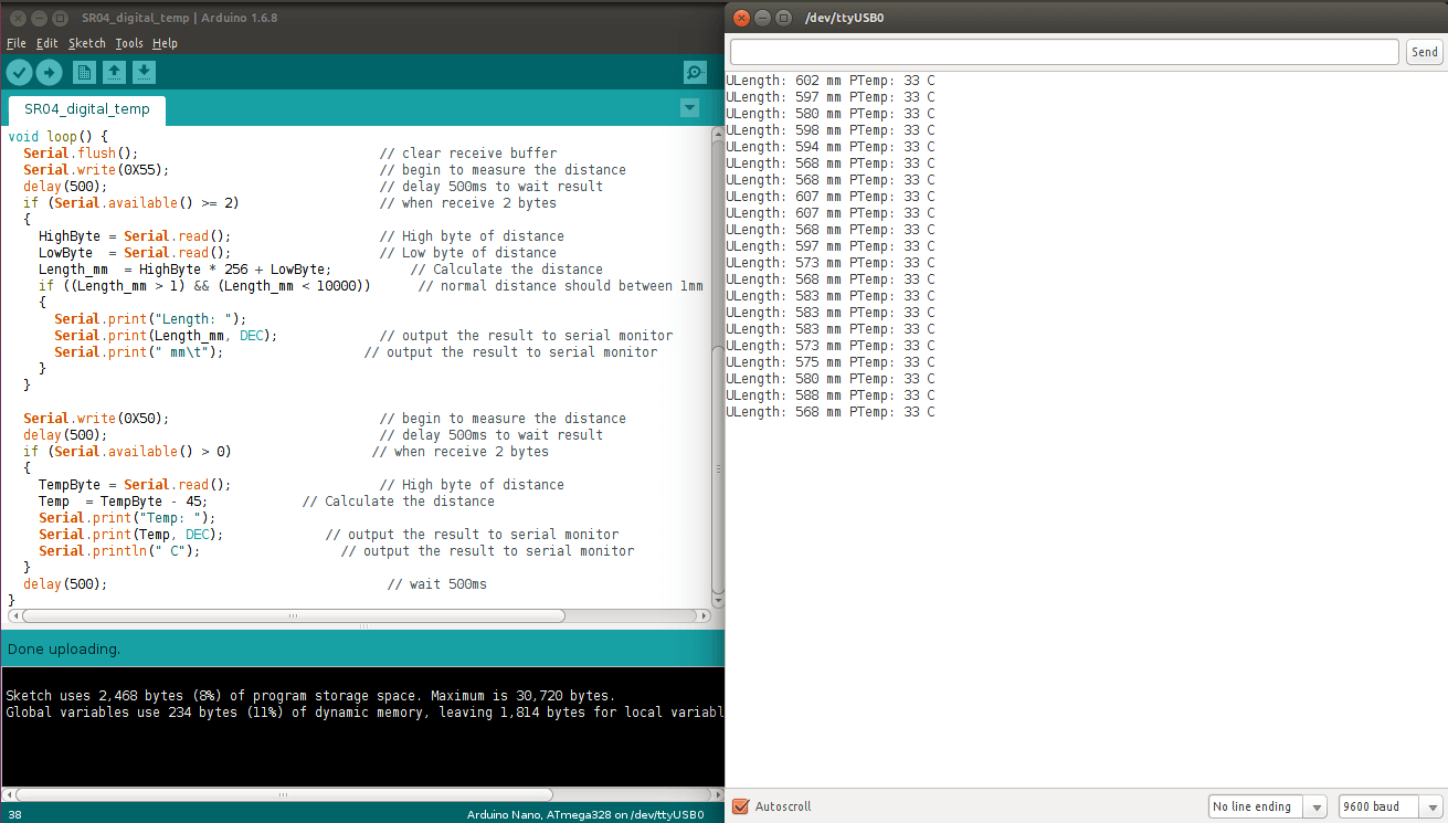
Place the shunt on the operating mode selection jumper to choose serial data mode. Attach the module to a serial port on your microcontroller. The Trig/TX pin connects to your microcontroller's TX serial transmit line. The Echo/RX pin connects to your microcontroller's RX serial receive line. Set the microcontroller's serial port to use 9600 baud at 8-N-1 (eight data bits, no parity, one stop bit). To start measuring the distance, output a 0x55 over the serial port and read back the two byte distance in high byte, low byte format. The distance returned is measured in millimeters. Use the following formula to obtain the distance as millimeters:
Millimeters = FirstByteRead * 256 + SecondByteRead
This module can also output the temperature when using serial output mode. To read the temperature, output a 0x50 byte over the serial port and read back a single temperature byte. The actual temperature is obtained by using the following formula:
Celsius = ByteRead - 45
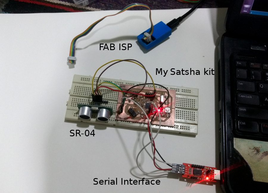
As shown in the photo beside, I've used my Atmega328 board for the testing various input devices.
Reading Distance from SR04

Reading Distance as well as Temperature from SR04
Analog Sensor Readings on Arduino

Switch as a input device
The simple form of the input device is button, which can be simply read by the MCUs. The following video is showing the use of simple push button as a input device, the code is written in a way to toogle the LED even the switch is pressed.
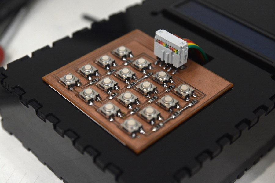
Simple switch as input device can be evolved into the device shown in the picture. It's a Matrix keypad with 16 keys, and can be interfaced with any micro-controller using 8 pins only. Pin budgeting is the major concern behind making matrix keypad. Otherwise one needed to have 16 individual pins to listen to 16 different buttons.
This keypad I'll be using in my final project. I've designed the keypad in Kokopelli that you can download from the download section.
I've used the 5x2 header as I wanted to use 8 pins in total and 8 4x2 header is not available. Here, the odd numbered pins(e.e. 1,3,5,7,9) takes car of columns, , and the even numbered pins (e.g. 2,4,6,8,10) takes care of each row.
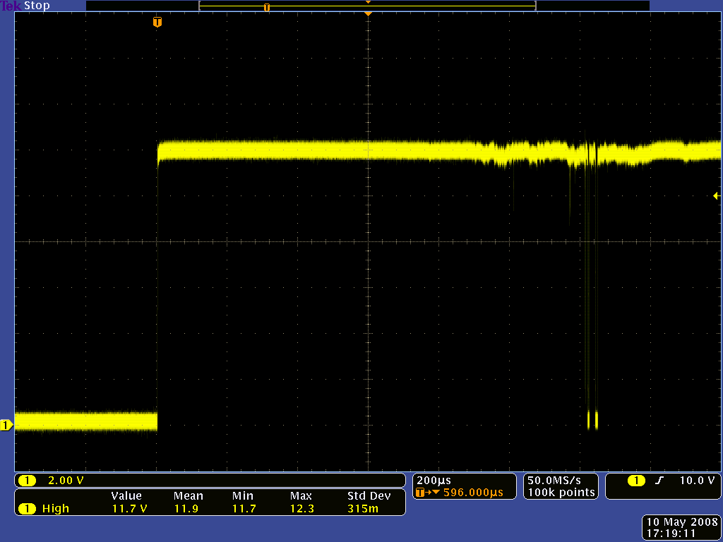
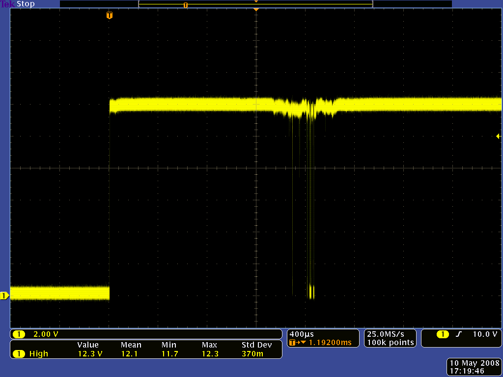
Switch Bouncing
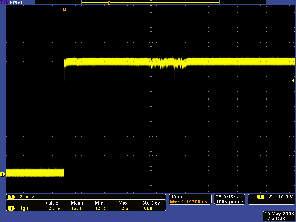
Switch bouncing is the is a real-world problem that happens too quickly for human perception but which can doom an electronics project. When a switch is toggled, contacts have to physically move from one position to another. As the components of the switch settle into their new position, they mechanically bounce, causing the underlying circuit to be opened and closed several times. As a result the computing devices i.e. micro-controller reads it as switch is pressed multiple times if proper care is not taken.
The method of reducing the chattering happening between contacts if knwon as De-boucing.
De-bouncing of a switch
When developing the embedded system we have to take care of bouncing phenomenon. So, de-bouncing is the process to eliminate the bouncing of contacts. There by resulting in the cleaner readout of the switch and eliminates the multiple opening-closing behavior of any mechanical switch.
De-bouncing can be done in following ways.
- Mechanical
- Electrical
- Software
Mechanical : Reduce the kinetic energy of the moving contact. This will reduce the force of impact as it comes to rest on the stationary contact, thus minimizing bounce.
- Use “buffer springs” on the stationary contact(s) so that they are free to recoil and gently absorb the force of impact from the moving contact.
- Design the switch for “wiping” or “sliding” contact rather than direct impact. “Knife” switch designs use sliding contacts.
- Dampen the switch mechanism’s movement using an air or oil “shock absorber” mechanism. Use sets of contacts in parallel with each other, each slightly different in mass or contact gap, so that when one is rebounding off the stationary contact, at least one of the others will still be in firm contact. “Wet” the contacts with liquid mercury in a sealed environment. After initial contact is made, the surface tension of the mercury will maintain circuit continuity even though the moving contact may bounce off the stationary contact several times.
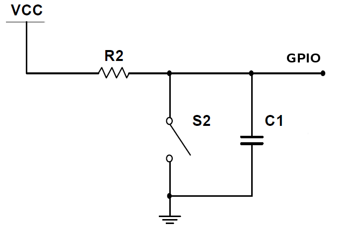
- Using mercury to “wet” the contacts is a very effective means of bounce mitigation, but it is unfortunately limited to switch contacts of low ampacity. Also, mercury-wetted contacts are usually limited in mounting position, as gravity may cause the contacts to “bridge” accidentally if oriented the wrong way. As the diagram is shows the circuit which consist of the capacitor and resistor. As soon as the user presses the switch th
Potentiometer - Reading analog voltages

Analog Voltage Reading

Download Original Files
- SR04_analog.zip
- SR04_digital.zip
- SR04_digital_temp.zip
- btnInput.zip
- reading_POT.zip
- keypadTest.zip
- satshakit_cnc.zip
- hello.keypad.zip