Plan

  • My plan for this project is to get the most difficult parts out of the way first and then do the things I’m better at.

  • I’m going to do the board design first, solder it and program, to make sure everything works before writing the program to do what I want.

  • With the basic concept working I’ll start on the design based on a rough 3D sketch I’ve done before hand. With the housing done I’ll try to implement as many weeks as I can. Something like the 3D printer, molding and casting or the vinyl cutter which I have more experience with. I think I’ll do the housing mainly using the laser-cutter and do a press-fit design.

Circuit Design and Milling

  • Starting off I was going to use two servo’s to control the up and down movement and the left and right. I made my design based on Neil’s servo board. We didn’t have any 22 µF capacitors so I had to find a way to use multiple capacitors and running them parallel instead. I found a page one the subject here.

  • Using the capacitors parallel I was able to use two 10µF and two 2µF capacitors.

  • I wanted to control the servos with an input so I started looking at the datasheet and there were some unused pins that I was able to use.

  • I used pin PA0 PA1 PA2 and PA3 as my input for four buttons.

  • I used an FCI to make the input easily changeable or if you just want to make the cable shorter or longer.

  • For the remote I made each button have common ground and they each connected to a separate pin on the FCI corresponding to their pins on the Attiny.

  • Soldering both boards didn’t take too long. I started with the 20 MHz crystal since it had given me a lot of trouble before. Next I soldered the Attiny and the rest was pretty straight forward.

Programming

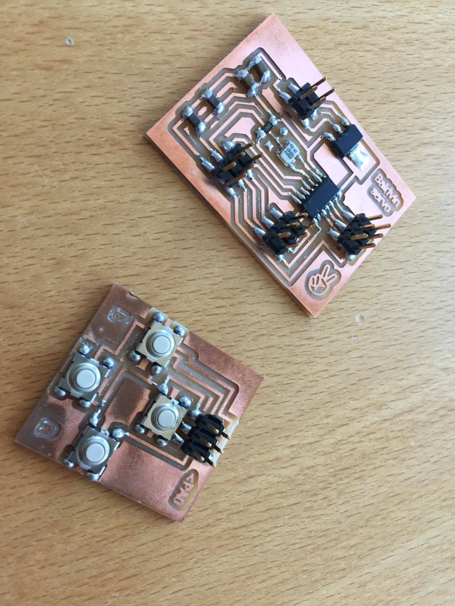
  • I wanted to get the boards done as fast as I could so I could get started sooner on the programming since I have little as no experience with programming. My plan was to get the programming of my back as soon as I could and get the servo’s functioning like I wanted, before doing the design of the whole thing.

  • I started of by modifying Neil’s original code and figure out how it worked. That wasn’t really going too well for me so I moved on to the arduino environment and found a library for servos.

  • The library is called RBD_Servo and you can find instructions on their side

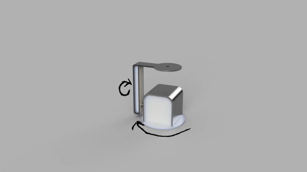
  • With great help from Baz I was able to write a code that could demonstrate everything I wanted the servo’s to do.

  • I did run into some problems and the servo’s were behaving strangely. I first tested the buttons to see if they would connect the pin to the ground and they did. In the code I had to add “INPUT_PULLUP” instead of just “INPUT” to get the buttons functioning properly.

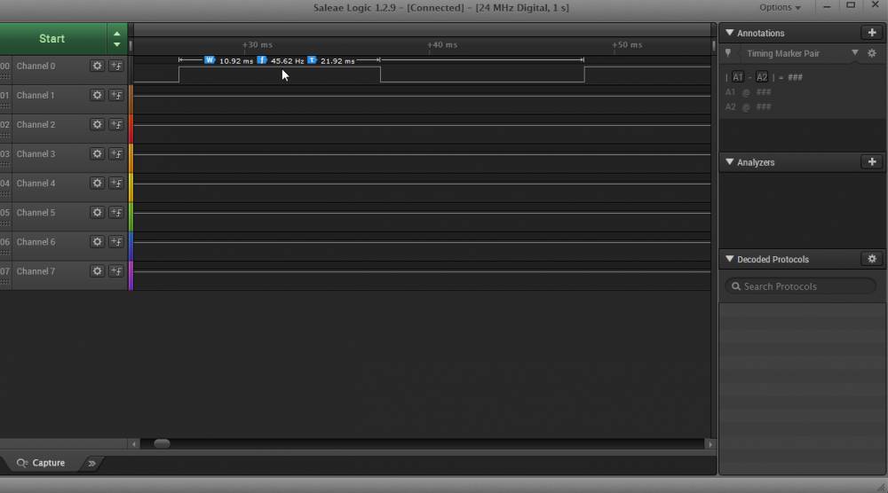
  • Still they were a little strange and with an logic analyzer I was able to detect the problem.

  • The servo’s go to a set degrees based on the length of the signal they receive. But they also need a minimum pulse signal to make them move. What I saw in the logic analyzer was that the minimum pulse signal was too long for the servo’s making them think they had to move more than 180 degrees.

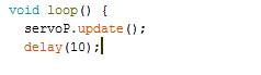
  • Also I had delay in the code that was of no use. I removed the delays and shortened the minimum pulse length to 0,5 ms instead of 1 ms.

  • Then the servo’s started going where I wanted them to and was able to finish the code.

  • Since the servo’s were going to be holding gear I had to constantly send updates to them to keep them still in the same place. Here is the code:

  • 
    // Arduino RBD Servo Library v1.0.1 Example - Move a servo with a 1-2ms pulse and 20ms interval to 90 degrees.
    // https://github.com/alextaujenis/RBD_Servo
    // Copyright 2015 Alex Taujenis
    // MIT License
    
    #include  // https://github.com/alextaujenis/RBD_Servo
    
    //telling the program which pins the servos connect to, and minimum pulse lenght
    RBD::Servo servoP(6, 500, 2000); //pin 6, 0,5ms - 2ms pulse
    RBD::Servo servoT(7, 500, 2000); //pin 7, 0,5ms - 2ms pulse
    
    //giving every button a name, buttonLeft etc.
    #define BL 2
    #define BR 3
    #define BU 0
    #define BD 1
    
    void setup() {
      servoP.moveToDegrees(90); //servo pan starting point to 90 
      servoT.moveToDegrees(90); //servo tilt starting point to 90
      pinMode(0,INPUT_PULLUP);
      pinMode(1,INPUT_PULLUP);
      pinMode(2,INPUT_PULLUP);
      pinMode(3,INPUT_PULLUP);
      
    }


    void loop() {
      servoP.update(); //constant updates to keep the servos in place
      servoT.update();
    
    
      //
      //
      // FOR LEFT
      //
      //
      
      if (digitalRead(BL) == LOW) {
        servoP.moveToDegrees(180);
    
        while (digitalRead(BL) ==LOW){
            servoP.update(); 
            servoT.update();
            //
            //  if left and right
            //
            if (digitalRead(BR) == LOW) {
              while ((digitalRead(BL) ==LOW) && (digitalRead(BR) ==LOW)){
                servoP.update();
                servoT.update();
                servoP.moveToDegrees(90);
              }          
            }       
          }  
        }


      //
      //
      // FOR RIGHT
      //
      //
    
      if (digitalRead(BR) == LOW) {
        servoP.moveToDegrees(10);
    
        while (digitalRead(BR) ==LOW){
            servoP.update(); 
            servoT.update();
            //
            //  if right and left
            //
            if (digitalRead(BL) == LOW) {
              while ((digitalRead(BL) ==LOW) && (digitalRead(BR) ==LOW)){
                servoP.update();
                servoT.update();
                servoP.moveToDegrees(90);
              }          
            }
          }  
        }


      //
      //
      // FOR DOWN
      //
      //
      
      if (digitalRead(BD) == LOW) {
        servoT.moveToDegrees(120);
    
        while (digitalRead(BD) ==LOW){
            servoP.update(); 
            servoT.update();
            //
            //  if down and up
            //
            if (digitalRead(BU) == LOW) {
              while ((digitalRead(BU) ==LOW) && (digitalRead(BD) ==LOW)){
                servoP.update();
                servoT.update();
                servoT.moveToDegrees(90);
              }          
            }       
          }  
        }


      //
      //
      // FOR  UP
      //
      //
    
      if (digitalRead(BU) == LOW) {
        servoT.moveToDegrees(60);
    
        while (digitalRead(BU) ==LOW){
            servoP.update(); 
            servoT.update();
            //
            //  if right and left
            //
            if (digitalRead(BD) == LOW) {
              while ((digitalRead(BD) ==LOW) && (digitalRead(BU) ==LOW)){
                servoP.update();
                servoT.update();
                servoT.moveToDegrees(90);
              }          
            }
          }  
        }
    
    
      }


Design

  • I had some ideas for what I wanted the project to look like and had made a rough sketch

  • Linda helped me with this part and suggested using plexiglass since it would be way stronger than the plastic in the 3D printer. Showed me some good ways to hold the servo’s without any screws getting in the way.

  • I started with making the bottom plate. It consisted of two circles each with two press-fit holes to make them stick together.

  • Then I did the housing which was also pressfit but the servos would be screwed in.

  • With the servos in place the thing was starting to take shape.

  • The whole time I had been using a USB cable to power the board but I went and grabbed a switch and a battery and made a back plate that could accommodate the switch.

  • I had also started on the arm that would hold the camera. It’s not strong enough to hold any large and heavy camera but I really had a light camera in mind such as the Gopro, plus the the servos are not powerfull enough to hold anything heavy.

  • I used a heatgun to get the arm to a 90 degree shape.

  • Then to I made the front plate which I also used a heatgun to get that 90 degree shape.

  • We had a webcam laying around so stuck it on and was also able to see live feedback from it on the computer when it moved around.

Molding and casting

  • I wanted to do somewhat of an joystick and decided to try doing it using molding and casting. So the basic Idea was to make an object that would sit on all four buttons and press them down.

  • I did the design in tinkercad for I was only using very simple shapes and I was overall quicker.

  • I downloaded it as .stl file and imported into Vcarve. I followed the same steps I did in week 12.

  • It ended up way thicker than I wanted, it works but I would rather do something like a 3D print for a shape this simple.

Thank you

  • I want to thank everyone in fablab Perth australia, Frosti, Þórarinn, Linda, Bas and everyone else who helped us. Without their help highly doubt we would have have been able to finish the academy and the project.