Assignments
The assignments for week 12 was to add an output device to a microcontroller board and program it to do something
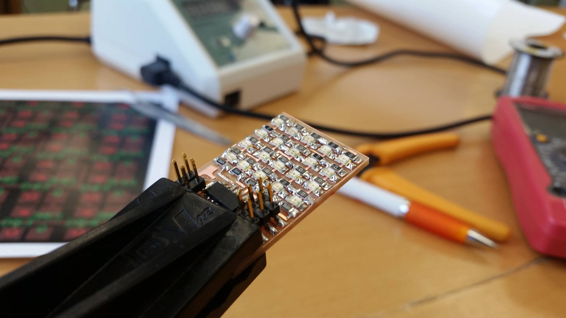
My plan was to make the hello.array LED board
The reason i choose that board is because i thought that it would be nice to understand the C code and be able to write my own LED patterns
hello.array.44
The hello.array board seemed like an interesting board to do
The cutting of the board and the soldering went very well and i am getting much better at soldering now
Instructions on cutting out boards using the modela can be found in week 4
Programming the board
To see if the board would work correctly i connected it to an AVRISP
The AVR gives you a green light if the board is working properly and luckily that was the case with my board
For the programming of the board i decided to use the linux enviroment
I saved the c file and the makefile into a folder on the desktop
You can find these files on the archive

Next i opened the terminal and found my folder there
My board and the AVRISP were now both connected to USB ports in the computer
Now i had to send the program to the board and run the makefile
To do so i wrote: sudo make -f hello.array.44.make program-avrisp2
If you're using an FabISP instead of AVR microcontroller write: sudo make -f hello.array.44.make program-usbtiny
This message came up when i was finished. The board was programmed!


Now i could unplug the AVRISP but i kept the board plugged in
Testing the board
Now was time to test the board
I ran through the code and figured out how to change patterns and the length of them
After an hour or so of programming the code seemed pretty straight forward and it was fun to play with
Final Project add on
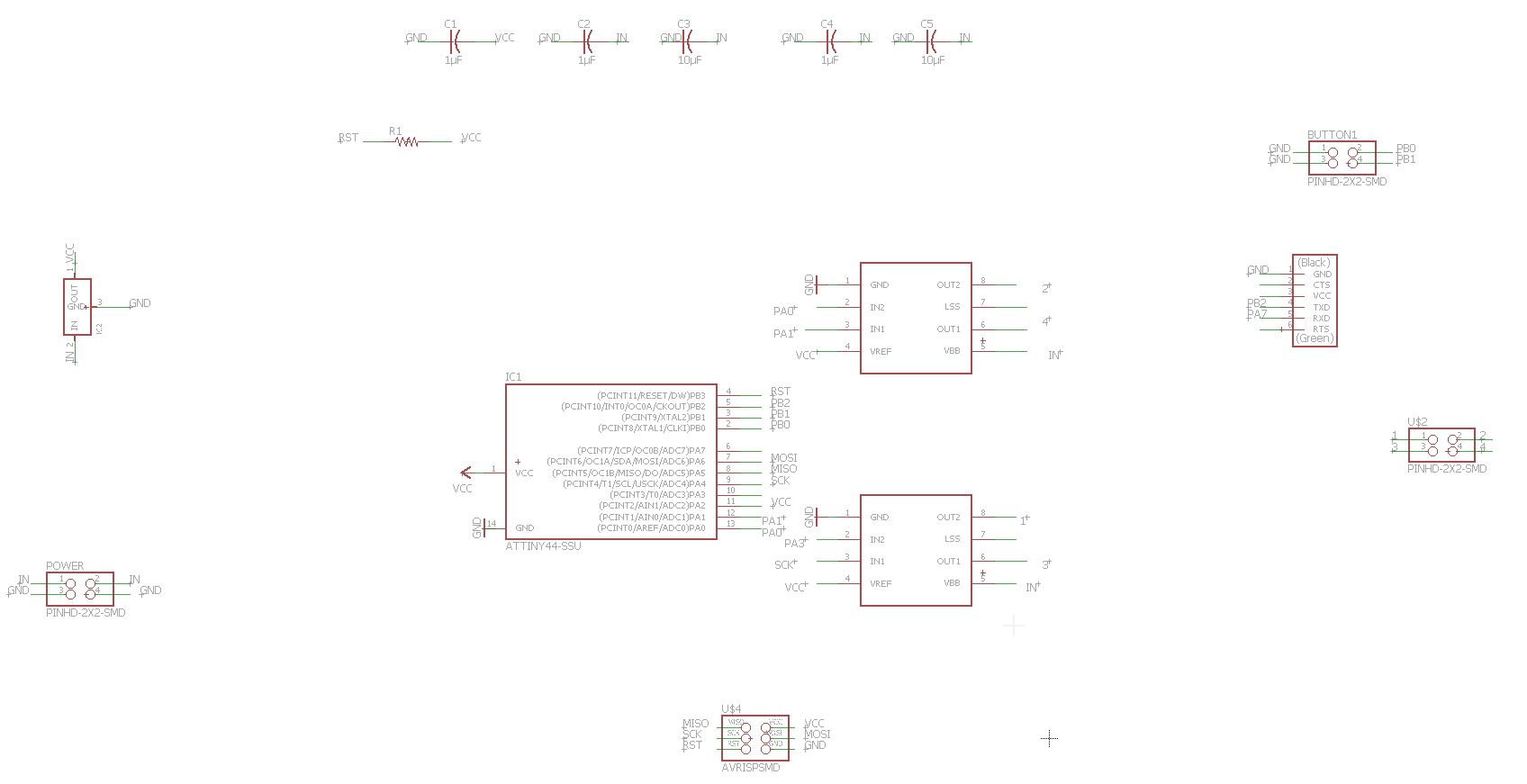
For the final project development i made another output board. Since my final project needed 2 boards to spin stepper motors i thought that it was ideal to redesign the Hello Stepper Bipolar board
I wanted to add FTDI pins so the board could communicate with programs from a computer
I also added 2x2 pins that are meant for buttons to connect to
I added the components i needed for the board to my schematic in Eagle
When my schematic was ready i made the layout for the board
This was the final outcome
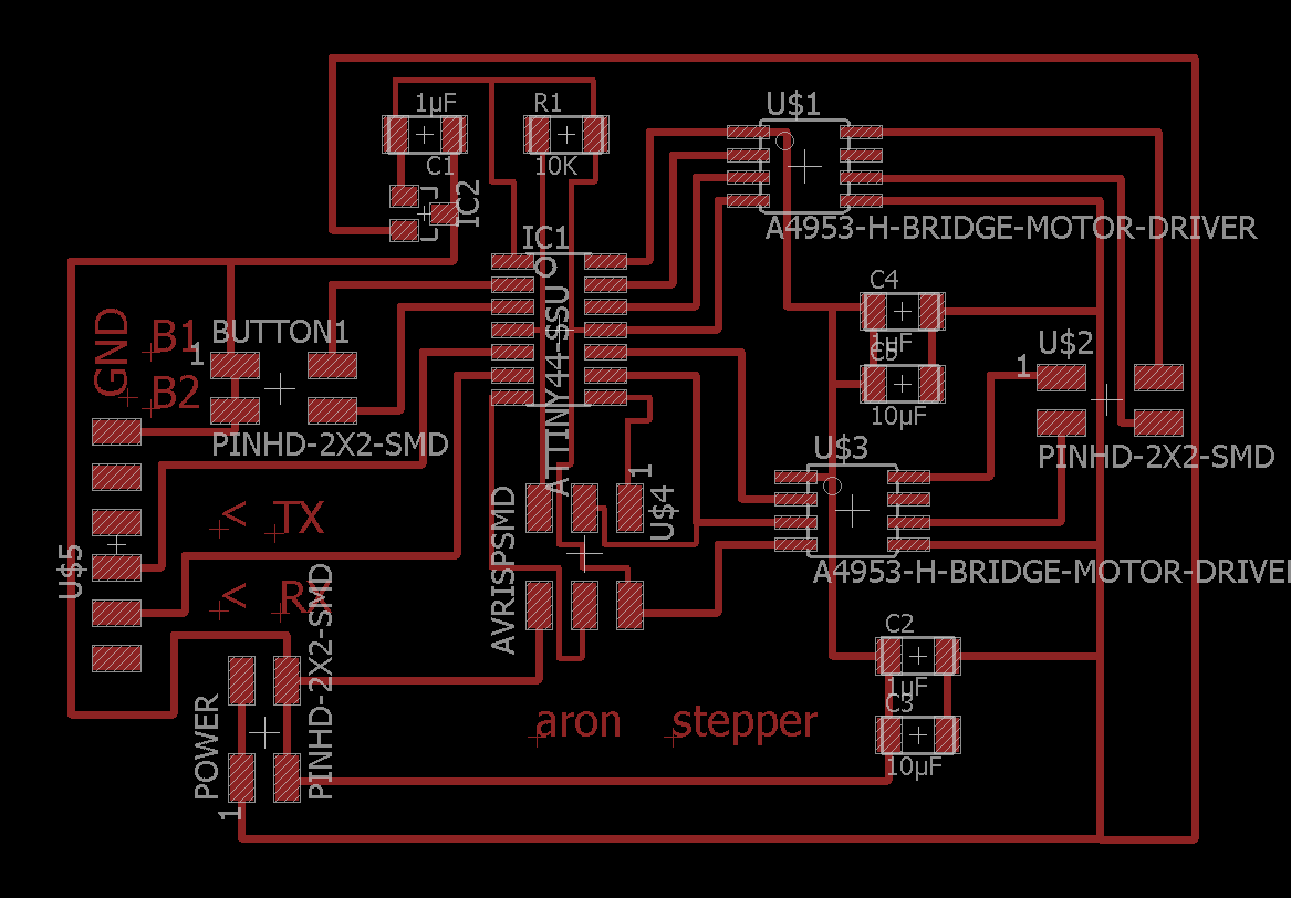
Now my next step was to cut out the board
Files from week 13
Final Project output files
Output devices in Final Project
I also included output device work in my final project
I drived a stepper motor by pressing a button
You can read about it here in the Electronics section

