Assignment
- Make something big (on a CNC machine).
- Document the process of design and production to demonstrate correct work flows and identify areas for improvement if needed.
- Explained how you made your files for machining (2D or 3D).
- Shown how you made something BIG (Setting up the machine, using fixings, testing joints, adjusting feeds and speeds, depth of cut etc).
- Described problems and how you fixed them.
- Included your design files and 'hero shot' photos of final.
In this week we have to design something big cutting or curving in CNC. In our FAB Lab there is a big CNC machine. That is "The Full Size PRSalpha CNC". The bead size of this machine is 96 x 48, CNC is the short form for Computer Numerical control. The CNC machine works as per the programmed instructions fed into the controller unit of the machine. The CNC machine comprises of the mini computer or the microcomputer that acts as the controller unit of the machine. While in the NC machine the program is fed into the punch cards, in CNC machines the program of instructions is fed directly into the computer via a small board similar to the traditional keyboard. PRSalpha CNC is a 3 axis machine (X,Y,Z).
Some more specifics about the shopbot milling machine
- Maximum Part Size: 2440 x 1220 x 150mm
- Software used: Partworks 2D & 3D
- Acceptable file formats: DXF, STL
- Mechanical Resolution: 0.015mm | 0.0006"
- Position Accuracy: +- 0.127mm | 0.005"
- You can cut and carve: wood, plastic, styrofoam and many more, but no metal.
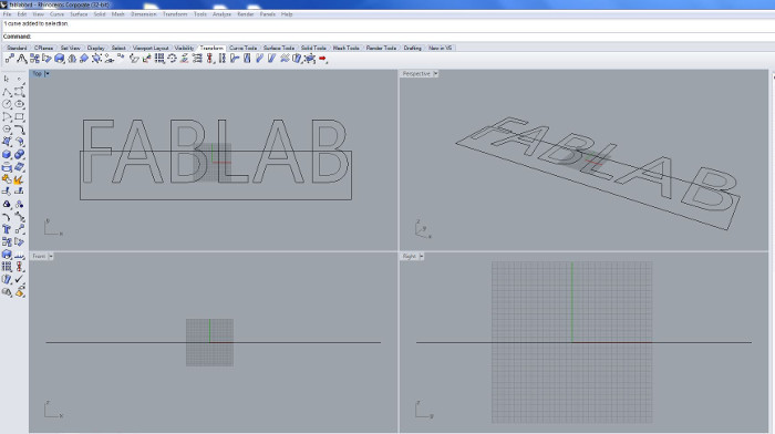
My plan is to cut a good sign board for our FAB lab. Our lab is a newly setuped lab and is not have any sign boards in the building. I planned to cut and engrave a special type sign board, which reflects the power of a fab lab. I started to design the sign board of our fab lab using the Rhino software. Its dimension is like Width - 100cm and height - 30cm. It is a multipurpose sign board, it can be hanged using the chains or can fix over the wall. Next step is the production of board in shopbot.
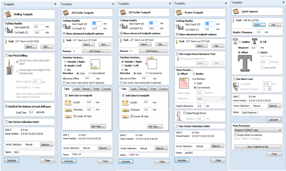
The design file is to be saved as .dxf file for "Vcarve software". I selected 12mm plywood sheet for doing this job. Open the design file with VCarvePro software. In my design there is Drilling, engraving, pocket cut and final cut is to be done. Each settings is saved as individual files. The settings are shown below.
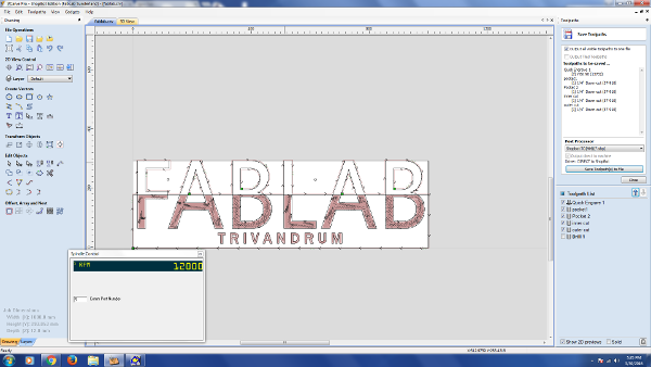
For each part work such as cutting, engraving etc., we have to set different tool paths for it. It can be done by selecting the job and apply the individual profiles from the software itself. I made profile paths for drilling the board-to fixing the job on the bed, 2D cut paths-for inside and out side cuts, pocket cut tool path and finally engraving tool path. All the settings are shown below. Once this is over we can save each tool paths with its name. For processing the job we just need to open the corresponding path file. So we have to be very careful during this step, if any mistakes in the setting may lead to error.
Next I have to fix my plywood sheet on the bed of shopbot, we can use screws for this purpose. Next switch On the Shopbot by turning on the power switch, Open the shopbot3 software which is already installed in our PC. Initially a reset message will come, we have to manually reset the machine. Next we have to set X,Y and Z axis to zero. For setting X and Y axis first identify a place which is the origin for my job and from the shopbot menu select X,Y axis to zero. This will be the origin of my job by clicking set X,Y axis to zero from the drop down menu ensures this. Next we have to set the Z axis,for this the tools shown below can be used from the shopbot3 zero axis settings set zero axis to zero, pressing yes will set the Z axis to zero by moving its Z axis automatically, we have to place the clip to the top portion conductive surface and the plate over the job.
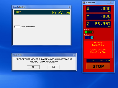


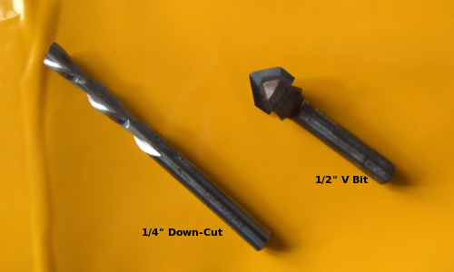
Next step we can start the job, so the path files which I saved earlier can be opened one by one through shopbot3. Before starting the job we need to select the corresponding bit for engraving, pocketing and cutting. The one I used for my engraving job is 1/2" V Bit and 1/4" Solid Carbide Down - Cut bit for pocketing & cutting. We fix the bit in collet and tight the collet nut using ER25 spanner wrench. Then we turn ON the dust collector and now the shopbot is ready to cut the design. The bit I used are shown below.
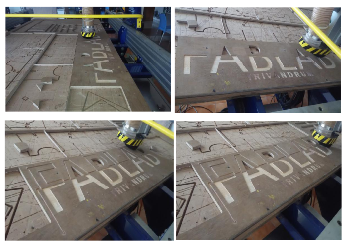
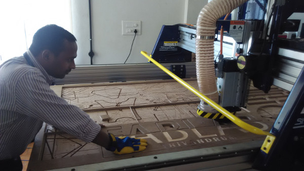
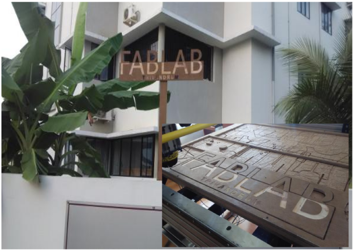
At last I got the "FAB LAB TRIVANDRUM" sign board. I just fixed it on a lengthy wood by screws. Placed the whole assembly in the corner of our building.
Download my Design files :
FAB Lab sign board (Rhino) 3DM Files