Assignment
- Redraw the echo hello-world board and add at least a button and LED with current-limiting resistor or design your own.
- Select and use software for circuit board design
- Demonstrate workflows used in circuit board design
- Shown your process using words/images/screenshots
- Explained problems and how you fixed them
- Done fabbercise today
- Included original design files (Eagle, KiCad, Inkscape, .cad - whatever)
Softwares for circuit design
In this week first I am going to study about different circuit designing softwares. There are many softwares available for designing circuits some of them are listed below:
Electronics PCB Design Using KokopelliMr. Francisco, our remote instructor told that, in MIT PCB designers are using Kokopelli software. Kokopelli is a software tool for computer-aided design and manufacturing. It is more powerful and safe and the circuits which are designed in Kokopelli software can be modified by anyone in the world. So I started working with Kokopelli, first of all we use it by downloading the hello world examples from the the fab archives. First download the circuit .cad file, then open the cad file with Kokopelli as shown below.

I am going to add three extra component in to the circuit an LED, Resistor and a Button switch. In kokopelli we need to write the codes, while the other softwares we have to draw the circuits. The programs can be modified as shown below.

I made all changes in coding and the code I changed is given below. Now it is ready to be exported for milling. We can give the resolution in pixels, a resolution of 40 is enough for milling. We have to save the two production files to .png extension one is for milling and the other for cutting. Once this is over next is to mill the PCB using Modela. Here I am not giving the details obout the setting up of modela because it's already mensioned in my electronics production week.
Changes I made in the coding:
Now move onto the machine, Switch it ON. Change the bit carefully to 1/64 for milling the traces. Using the Fab Module move the head to the point where you want the origin to be. Then correct the height of the bit. We want to have it just touching the surface. Now in the Fab Modules give make .rml command and then send it to modela. Wait till the work is done. After cutting the traces change the bit to 1/32 and repeat the process using Fab Modules using cut board .png fil. This will make a cut around our circuit so that we can remove it from the larger board.
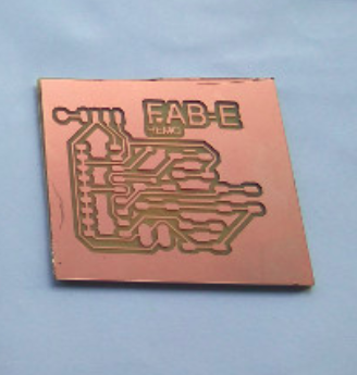
Picture of the Hello World Board: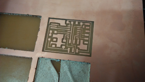
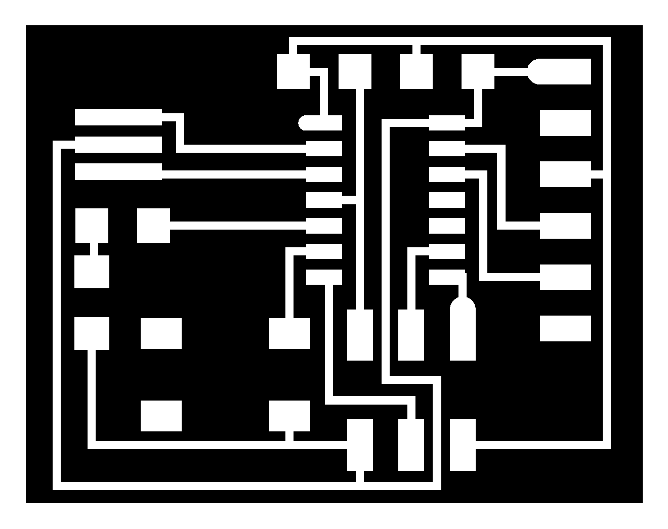
Once the board is milled and cut it is ready for soldering the components in appropriate positions with the help of my circuits position diagram. This is an important step because all are SMD pads there is more chances of confusions in placing components,also identifying the polarities of diodes and IC's from the PCB's are difficult. So every time we must solder it by refering our layout/position diagram. This reduces the chances of errors while soldering.

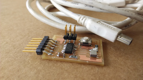
After the completion of soldering next step is programming part. We can programm it by using Fab ISP which I made in electronics production week. Inorder to programm it we have to interconnect the two boards, so for that I made an FRC cable using ISP header connectors and ribbon cables. The methods are very simple and is as shown below.

This FRC cable need in Embedded Programming week. So I advance to make the cable.


The above figure shows the interconnection between "FAB ISP" to "Hello World Board". This is the setup for programming my "Hello World Board".
Download Production files
My Hello World PCB milling PNG file
My Hello World PCB cutting PNG file
My Hello World Kokopelli CAD file
Extra Assignment 1
PCB wizardIn this week as a part of my main assignment, I planned to design a remote control circuit which is a part of my final project in PCB wizard software. PCB Wizard is a powerful package for designing single-sided and double-sided printed circuit boards (PCBs). I started working on it and desinged a circuit
Remote controlIt is built around encoder IC HT12E (IC1), 433MHz RF transmitter module (TX1) and a few discrete components. Switches S1, S2, S3 and S4 are interfaced with AD8 through AD11 of encoder IC1 for forward (FWD), reverse (REV), left (LEFT) and right (RIGHT) motions, respectively. Resistor R1 is connected between oscillator pins 15 and 16 to set the transmitter frequency. IC1 is permanently enabled for transmission by connecting its TE pin to ground. The figure below shows the hand sketch of my remote circuit. When any switch, say S1, is pressed, the corresponding data is serially transmitted through the RF transmitter module. A 9V battery is used to power the circuit
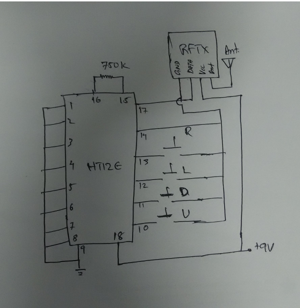
The schematic and the design files are shown below.


Extra Assignment 2
EagleI am familier with Eagle, Eagle PCB Design Software is a powerful and flexible design software that can produce commercial circuit boards easily. It is easy to learn and use. Eagle freeware is available as EAGLE Light Edition but this version is enough to design a complex circuit.
Limitation of the light edition of eagle:
- Useable board area is only 100 * 80 mm
- Only two signal layers can be used (Top and Bottom)
- Schematic Editor can only create two sheets.
Apart from these limitations EAGLE's Light Edition can do anything a professional edition can do. I have been using EAGLE Version 7.4.0 for Linux (64 bit) Light edition to develop circuit boards and it seems to be professional yet easy to use.
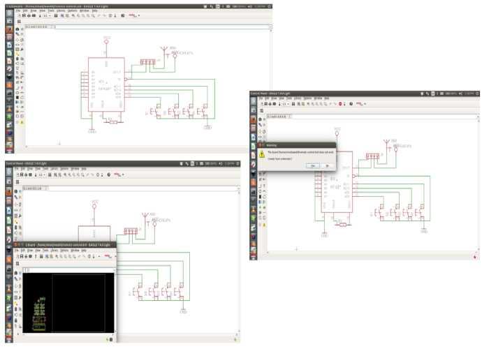
I tried to design a the same remote control circuit in eagle and I succesfully completed that. The circuits are shown below

Download my Remote control board design files(Eagle):
Remote Control EAGLE BRD file.
Remote Control EAGLE SCH file.
Learning outcome
After completing this weeks assignment, I am very happy that I learned so many things, installing the softawres, using different GUI platforms, drawing circuits and processing it etc.