Assignments:
Make the Fab (tiny) ISP in-circuit programmer.Learning outcomes:
Tasks:
This week first I am going to study about electronics, different electronics component types and its uses. Then finally I have to make a FAB ISP board and program it. As I am an Electronics Engineer, I very well know about electronics circuit and components.
What is Electronics?
Electronics is the branch of science that deals with the study of flow and control of electrons (electricity). One who want's to know more about for the electronics there are more informative sites are available in the internet, some of them are:
Here I am giving some details about the electornics components which we use for our Fab Academy.
Electronic componets- Switches
- Diodes
- Resistor
- Capacitor
- Transistors
- Potentiometer
- Motors
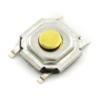
A switch responds to an external force to mechanically change an electric signal. Switches are used to turn electric circuits ON and OFF and to switch electric circuits. Basically what this means is that when you push down or flick a switch you are allowing current to flow through to the rest of the circuit.
We have many different kinds of switches the most common are Toggle Switch, Push button Switch, Selector Switch. In Fab we are using Tactile and SPDT switches.
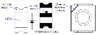
Diodes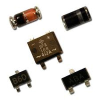
A Diode is the simplest two-terminal unilateral semiconductor device. It allows current to flow only in one direction and blocks the current that flows in the opposite direction. The two terminals of the diode are called as anode and cathode. The characteristics of a diode closely match to that of a switch. An ideal switch when open does not conduct current in either directions and in closed state conducts in both directions
There are many different types of diodes the most common are: Zener Diode: The Zener Diode allows current in reverse direction when the applied voltage reaches the breakdown voltage. (Based of principle of zener breakdown.)
Light Emitting Diode: The LED converts current into light. This type of diode is especially popular and is most commonly found in small electronics stop street lights and we may even see it finding its way into house lighting being cheaper and more Eco friendly.
Resistors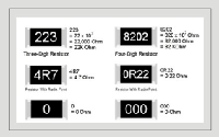
The resistor is a passive two pole component used to limit the amount of current that is allowed to flow at any given time as well as the voltage.
Capacitors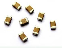
A capacitor is a two-terminal, component used to temporarily store a charge in an electric feild. This is use full in Electrical Engineering because it can be used to smooth out varying DC supplies aswell as filtering circuits (high pass, low pass or band pass) they are even used as temporary batteries.
The most common types of capacitors you will find are: Supercap: Also known as a ultracapacitor, as the name implies these capacitors have very large amounts of capacitance.
Elecrtrolytic Capacitor: These are a type of capacitor that are polarised (they can only work in one direction) these are able to offer high capacitance values mostly above 1 μF. These are mostly used for low friquency applications
Ceramic Capacitor: Is a type of capacitor that can store a charge anywhere from a picofarad to around 0.1 microfarad.
Transistors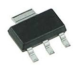
Transistors are small mostly 3 pole component made of elements in the group 4 in the periodic table, Silicon being the most common. To understand it think of it like this, Your brain has billions upon billions of neurons. The neurons let you think and remember things, Computers act the same way except the computers neuron is called a Transistor.
Potentiometer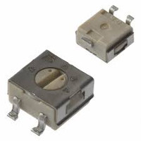
A Potentiometer is a knob that has variable resistance which can result in the dimming of your lights or even sending information back to your micro controller this component normally has 3 poles also called a 3 pole resistor it works in the same way as a voltage divider except for the fact that this has variable outputs. You will often find these in house holds or sound controllers.
Motors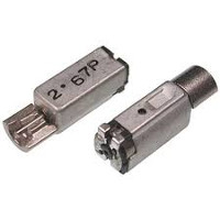
Motors is a device that converts direct current into mechanical power. They rely on the forces produced by magnetic fields. It does this by having a coil of wire with a current running through it generates an electromagnetic field. The direction and magnitude of the magnetic field produced by the coil can be changed with the direction and magnitude of the current flowing through it.
The most common types of motors are
DC motors : This Motors simply starts spinning if you give it DC connection the speed and direction all depends on the arrangement of the positive and negative poles as well as the amount of current you put through it.
Servo Motors: These motors are awesome because they can turn to any specific location within 660 or 180 depending on the servo we have .
Stepper Motors: The main difference between them and all the other motors, is the way they revolve. Unlike other motors, stepper motors does not continuously rotate Instead, they rotate in steps . Each step is a fraction of a full circle. This fraction depends mostly from the mechanical parts of the motor, and from the driving method.
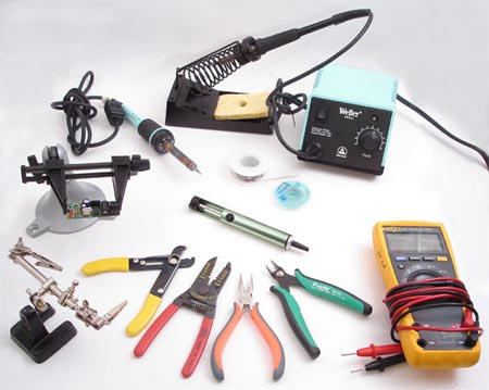
Electronic Production
Electronics production is making of our circuits in to printed circuit boards and soldering the components over the PCBs in respective positions using solder. Electronics circuits are the one,which different types of passive and active components are connected together to do a specific function. The circuits are designed using electronic cad sofwares and the PCB's can be made, after that we will solder the components over the PCB using lead. Here I am listing some tools that is used for the electronics production.
Fab ISP production
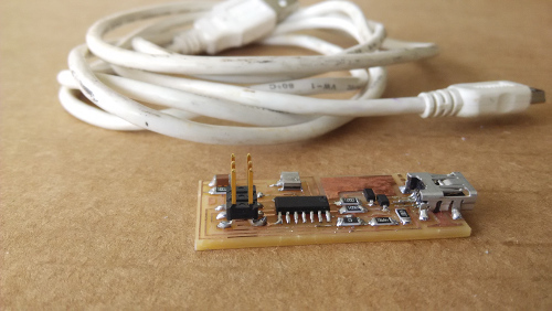
The FABISP is an in-system programmer for AVR microcontrollers, designed for production within a FabLab. That is, it allows you to program the microcontrollers on other boards you make, using nothing but a USB cable and 6-pin IDC to 6-pin IDC cable. It's based on the USBtiny and V-USB firmwares, which allow the ATtiny44 to perform USB communication in software. Programming can be done through avrdude. The FAB ISP was made during My Pre Fab Academy course. The detiails on how to mill and make the ISP is given below.
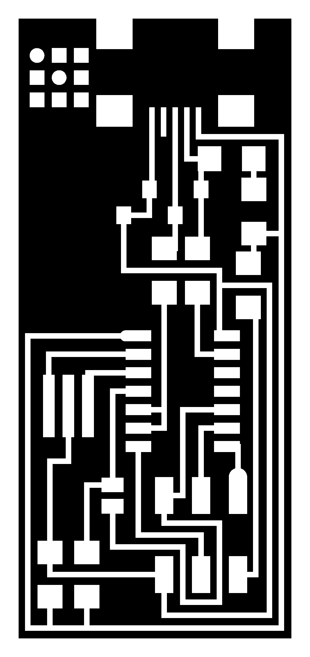
The FAB ISP production files are already available in the Fab academy archives, I downloaded the files from Fab academy 2015 archives. To mill the Hello ISO board designed by Mr.Neil. Opened it in kokopelli (It is a PCB Designing software) got the Trace .png and Outline .png. The next step is to mill the PCB, for making the PCB we have modela CNC in our lab. Modela is a printed circuit board (PCB) milling machine, it can do milling and cutting of the PCB's. It can be controlled by fabmodules; The fab modules provide a set of software tools for personal fabrication, intended for use with machines common to fab labs. The fab modules which accepts the .png extention file and next we move to mill the pcb, for that open Fab Modules and give .png as the input format, select modela as the machine. Then load the traces .png file and then make path. Leave the settings as default.
Workflow:
Milling the PCB
I am giving the steps for PCB milling on the Modela. Open the terminal
type:
"fab" - Enter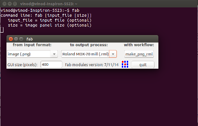
Select the input format (.png file).
Select the output process (Roland MDX-20 mill(.rml)).
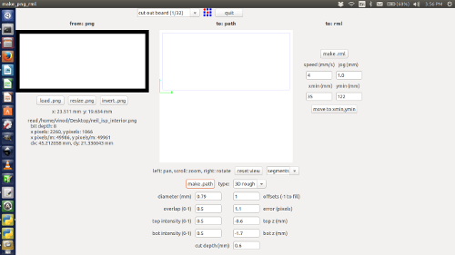
Select the workflow (make_png_rml).
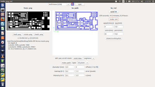
Click the "load.png" button and select our project work(.png).
Click the "make.path" button and view type select "segments".
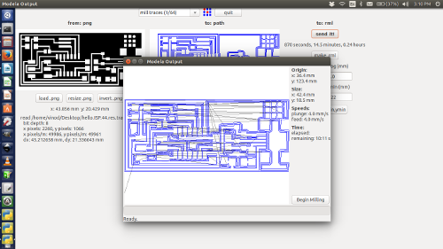
Click the "make.rml" button and the project job send it to the PCB Milling machine befor machine setup.
MILLING MACHINE SETUP
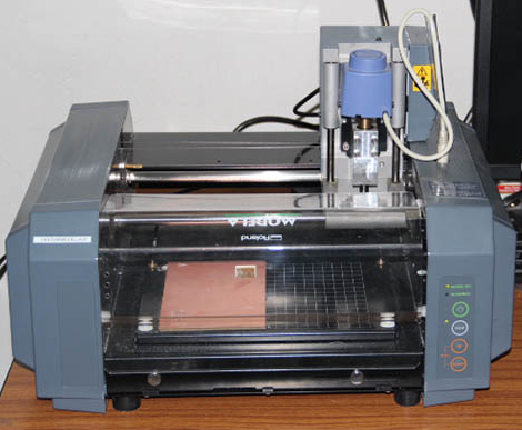
In our fab lab we are using " Rolland Modella MDX 20 " for milling and cutting the PCB's. The Rolland Modella MDX 20 is an affordable machine, it is a multipurpose machine which can perform scanning and milling work. This machine is also used to make the product mold.
First I remove the modela bed and mounted the copper board (sacrificial layer) on the bed using double sided tape. For the sacrificial layer copper board is to placed like non-copper side is facing up(Fig.1 & 2).
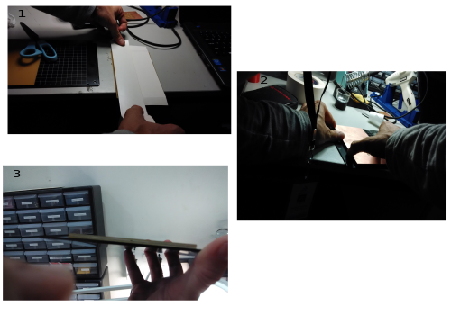
Layer using double tape(Fig.3). Make sure that there is no air bubbles present between the sacrificial layer and copper board. Presence of air bubbles cause height difference on the copper board which may further lead to broken the bits.
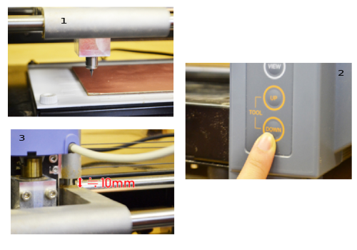
Put an end mill in as much as possible. Push the button of "DOWN" and lower the position of an end mill. Please refer fig.3.
Cutting the PCB
I am giving the steps for PCB cutting on the Modela.
Select top first "mill traces(1/32)".
Click the "load.png" button and select our project work(.png).
Click the "make.path" button and view type select "segments"
Click the "make.rml" button and the project job send it to the PCB Milling machine.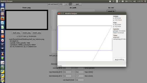
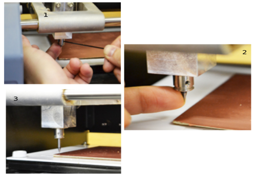
Now move onto the machine, Switch it on. Change the bit carefully to 1/64 for milling the traces. Using the Fab Module move the head to the point where you want the origin to be. Then correct the height of the bit. We want to have it just touching the surface. Now in the Fab Modules give make .rml command and then send it to modela. Wait till the work is done. After cutting the traces change the bit to 1/32 and repeat the process using Fab Modules using cut board .png fil. This will make a cut around our circuit so that we can remove it from the larger board.

Soldering
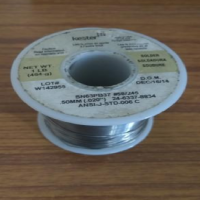
It is a process in which two or more items (usually metal) are joined together by melting and putting a filler metal (solder) into the joint, the filler metal having a lower melting point than the adjoining metal. Here i am using SN63PB37 solder (Tin-lead (SN-PB) solders),SN63PB37 solder used principally in electrical or electronic work.Soldering Station is weller WES51.
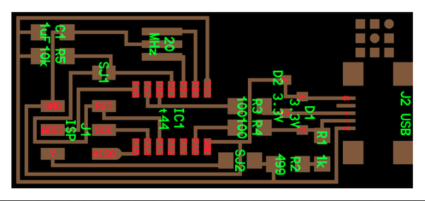
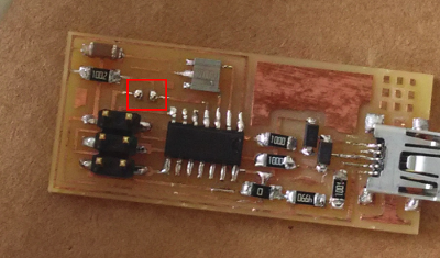
Now as we have the board, it's time to start soldering the components to the appropriate positions with the help of schematic/position diagram which is shown below. As a good practice, Mr.Francisco told all to write down the components in a paper or book and draw a box corresponding to each component. Then we took the components and placed them in their corresponding boxes. This way we won't mix up anything and it's easy to solder as the components are kept handy.
After soldering we have to check under the magnifier if the connections are proper and if time allows, do a continuity check too.
Programming the Board
The prerequisites for programming your board are
1.Latest version of avrdude in our PC
2.A mini USB cable
3.firmware of the board
When you have all the above try to flash the Firmware into the board.
The steps to be followed are :
You can download and extract the firmware from FAB Archives
Open a terminal over there and give the following commandsmake clean
make hex : If we are using an Atmelice isp make that change in the makefile [change to atmelice_isp]. If we are using USBtiny then change to that.
sudo make fuse : its run Successfully.sudo make program .
last our board should be programmed to work as an ISP.
The soldering jumper should be removed after flashing the firmware.
Production file Download :
Extra Assignment - 1
I tried to design the FAB ISP in Eagle Software. I successfully completed the design.
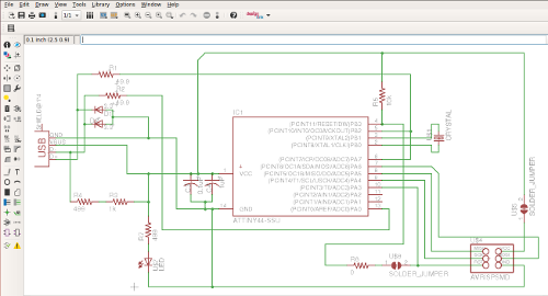
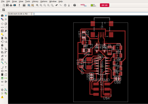
I already milled the FAB ISP Borad of Mr. Neil. So I skipped the milling proces of my FAB ISP board.