Assignment
- Design, make, and document a parametric press-fit construction kit
- Cut something on the vinyl cutter
Learning outcomes:
Evaluate and select 2D and 3D software
Demonstrate and describe processes used in modelling with 2D and 3D software
Tasks:
Modelled experimental objects/part of a possible project in 2D and 3D software
Shown how you did it with words/images/screenshots
Included your original design files
This week's assignment was to create a parametric press-fit using Laser cutter and made a 2D design that to cut using vinyl cutter.
Parametric press-fit construction kit
This week's project was to create a parametric 2D design and cut it out on the laser cutter. Parametric design is a process based on algorithmic thinking that enables the expression of parameters and rules that, together, define, encode and clarify the relationship between design intent and design response. Parametric design is a paradigm in design where the relationship between elements is used to manipulate and inform the design of complex geometries and structures. Parametric modeling systems can be divided into two main types:
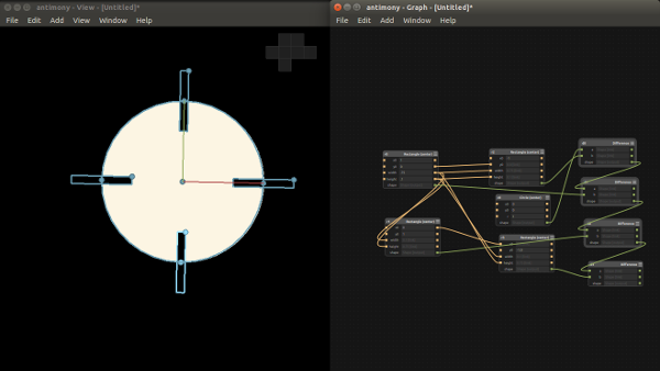
For this project I used Antimony design software. I have used this software in My Pre-fab Academy time (Oct -Nov 2015). I found this software easy to use for make a simple shapes. The one thing I like about Antimony is that you can make a variable and be able to change a size and have it propagate your design.
Make a press fitTo start my press fit kit. I have learned to design a parametric design in Antimony and I created a simple circle and then added some rectangles to it. Each rectangle was cloned and the parameters tie together so if any one need changes they can do it. I completed the design of it, here I planned to make a press fit structure (with the circle I designed) using the 3ply carton sheet of 3mm thickness.
Once completd the the design for laser cutting we need vector files, in antimony we can export the output in to .PNG or .STL file formats. So I exported it to PNG format.
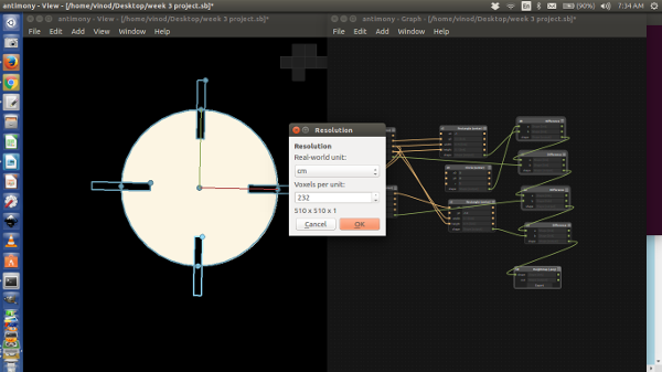
From the lecture of Neil about Antimony, I found out that we can use variables in script for defining shape parameters.
My Laser cutting work.
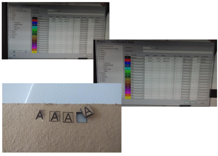
To use the laser I had to convert the png what I exported from antimony, for that I just opened it with corelDRAW and converted to a svg. Later I opened it with Inkscape as I am not so familier with corelDRAW. I take the bit map of my png and changed the color for laser cutting. I set the laser to the recommended setting of 85% power 3 speed and 6000 Hz as a test to see if it will cut all the way through. I start cutting......
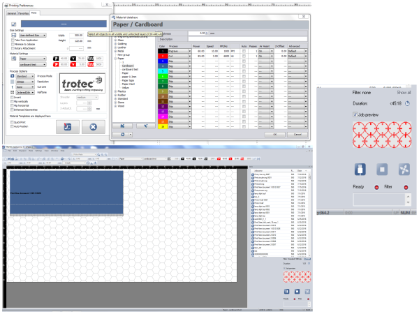
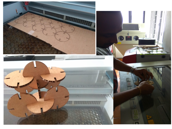
This figure shows cutting materials in laser cutter. First image shows the cutting and engraving parameter editing. 2nd and 3rd shows the material part in laser cutter. In our fab lab we have Trotec Speedy 100 laser cutter for cutting. Finally after press fitting, I got a good 3D structure and is shown below.
Download My Press Fit Design Files
Press fit PNG file (Exported from Antimony)
2D design Cutting on the vinyl cutter
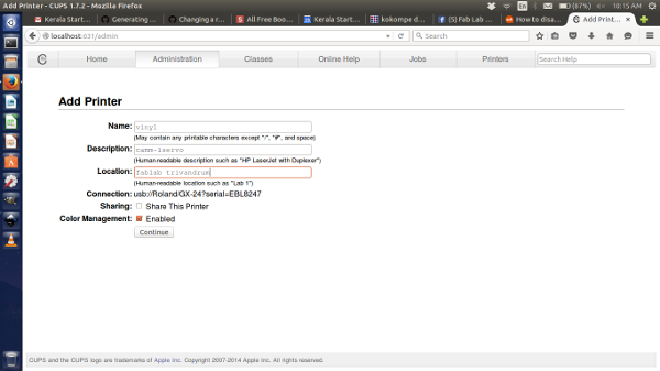
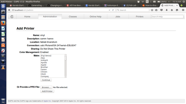
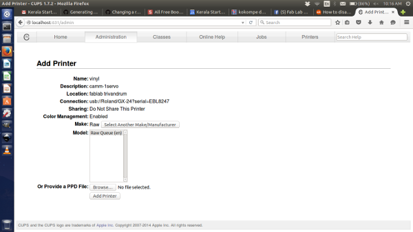
"vinyl cutter" installation in our computer
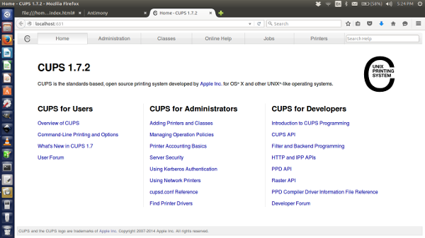
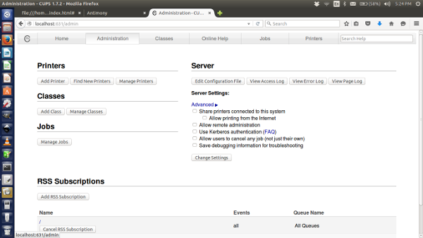
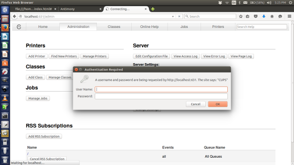
Using C Unix Printing System (CUPS 1.7.2) we created a new profile for the vinyl cutter. Case has to be taken while naming the device, it should be "vinyl" and it is case sensitive Then each of us made a design for cutting. I chose to cut out my initial (BG). Then we were taught how to form a sticker properly and the steps to be followed.
First we type "http://localhost:631/" in a browser. CUPS 1.7.2 window opening.
2D Design Printing
First we start to design a logo and save to .png format. Then go to terminal in your computer.
type:
"fab" - Enter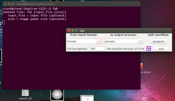
Select the i/p format (.png file).
Select the o/p process (vinyl cutter).
Select the workflow (program).

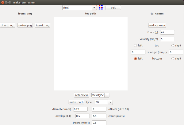
Click the "load.png" button and select our project work(.png).
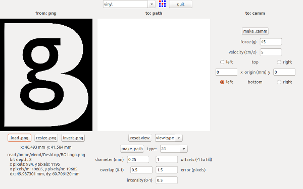
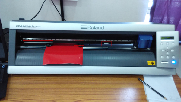
First we check whether the vinyl sheet loaded properly in the vinyl cutter. We fix the vinyl sheet between the white marked area close to left side of the vinyl cutter machine.
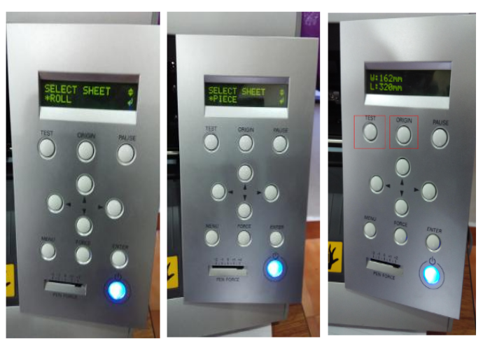
Give a test print.
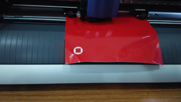


First one is my design and Second one is vinyl cutter print out.
Download My Design Files
Extra Assignment - 1
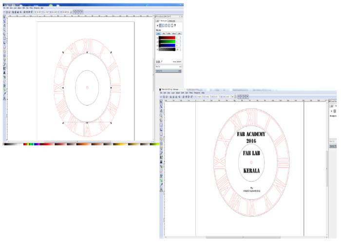
I started to design a FAB Clock. This project is my pre fab idea, that time I can't design or make this project. Now I am trained to design using Inkscape Software. The stages of the designs are shown below:
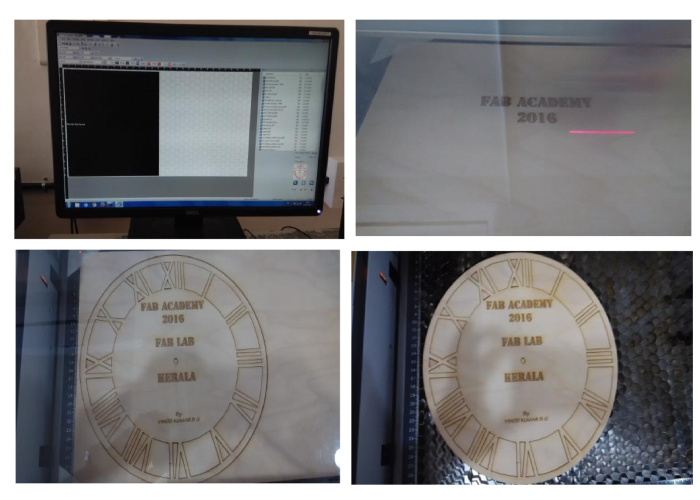
STAGE ONE: Design on Inkscape Software.
Design was made in Inkscape and then the saved .svg file was copied to the PC connected to the Laser cutter.There is a job control software for the machine installed in the pc. The software only runs in Windows OS.
Open the .svg file print the file, after selecting the trotec engraver click preferences there we have to select the materials its size, dimension of the job, power, velocity etc can be given. The power and velocity will vary from material to material. We have to set all these and once we pressed OK button job control will get opened, from there you can select the file and place the file in the set postion for cut. The video below shows the cutting process.
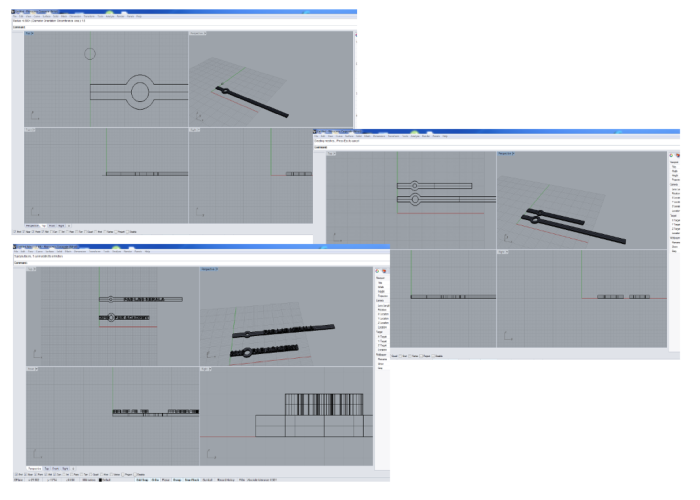
STAGE THREE: After cutting I started designing the Hour and Minute hands of the clock using Rhinoceros Software
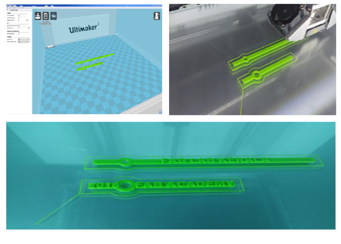
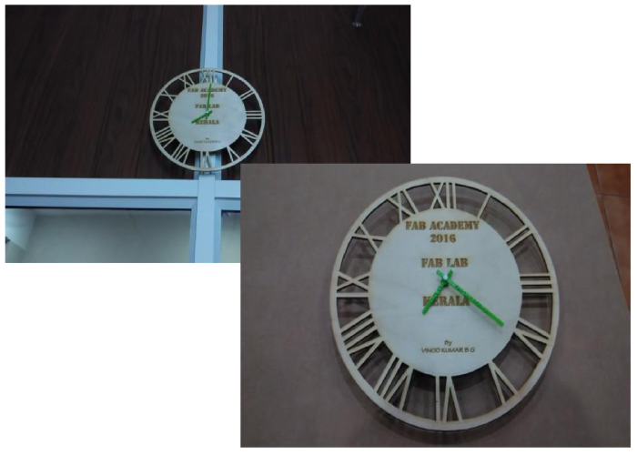
STAGE FOUR: After Finishing the design I printed the above in ultimaker 3D printer. Now my parts are ready for assembling. I assembled the whole thing, it was a wonderfull experience for me. Finally I got a beautifull FAB Clock. This clock we are using in our lab.
Download My Fab Clock Design Files
FAB Clock arrows Rhinoceros file (3dm)
Extra Assignment - 2
To design, cut and fix a press-fit kit.
Press-fit :1
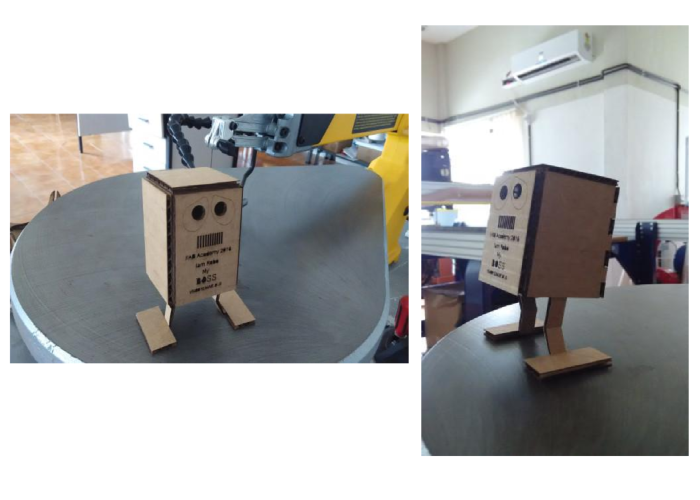
I designed a foldable press-fit robot using 3 ply carton sheet. The design was made in Inkscape software. In the folded areas I give a doted red line, you can see the design file.
First I draw my design in a paper.
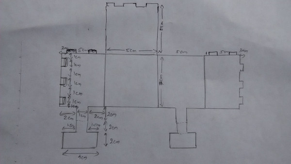
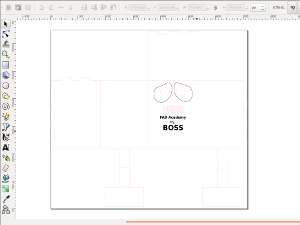
Next I designed it in inkscape.
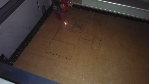
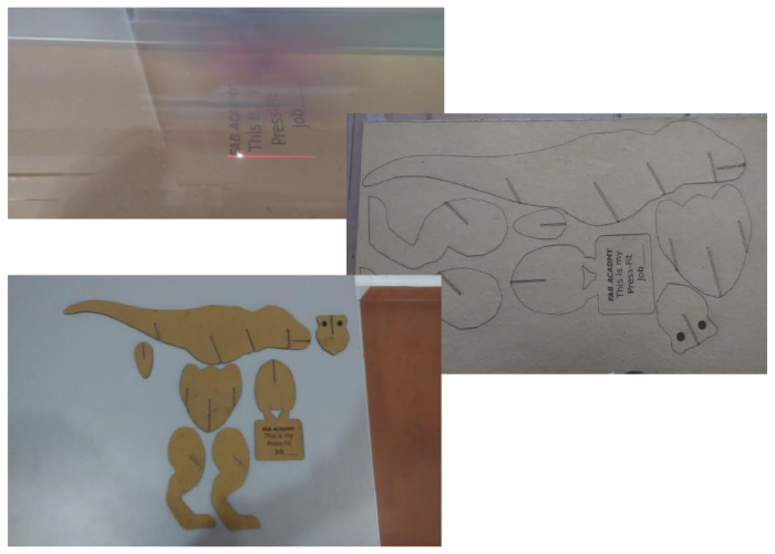
The file after design we have to cut it on the laser Cutter. The figure below shows cutting of my job in laser cutter.
After the laser cut I got my parts like this:
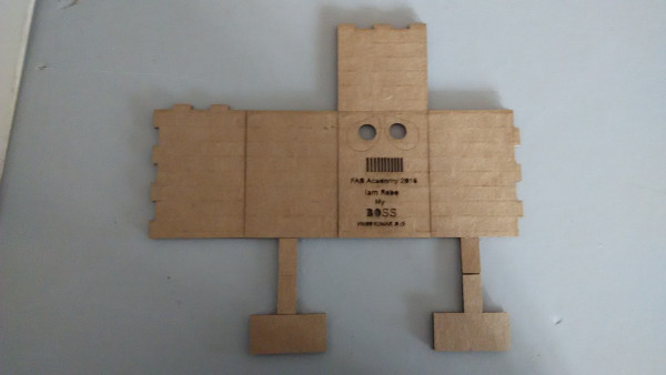
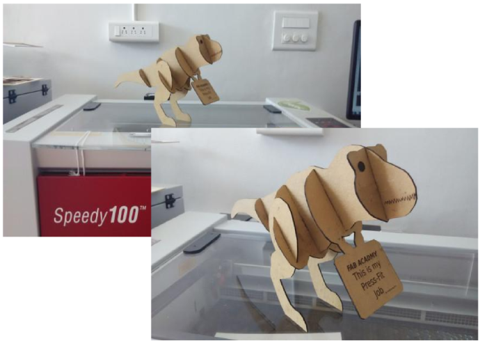
Next is very simple step just press fit the parts.
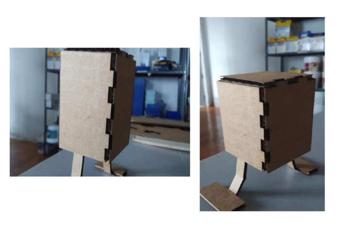
The output is like this:
Download My Robot Design Files
Extra Assignment - 3
Press-fit :2
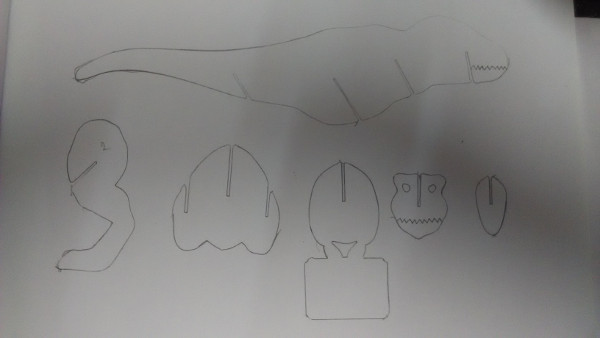
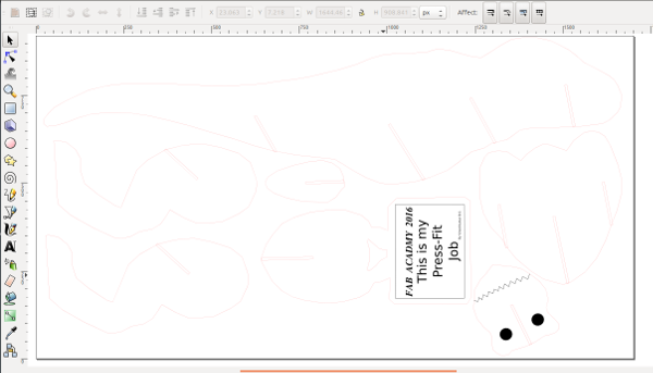
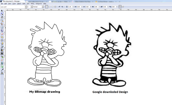
This time I designed a press-fit design, the dinosaurs. In FAB 11 program there was a laser cutter company they showed a small dinosaurs model in a craft wood (press-fit model), I like the design. So I plan to make the same. First I drawn the diagram in a paper and scanned the paper saved it as JPG file. Then I opened that file in a Inkscape software and create the bitmap drawing of it.
I made the 2D design for the dinosaurs using Inkscape software.
I want to cut the design in a card board sheet. First I check the cutting speed and laser power. We can change the speed and power of it and cut a small design this we are doing to check whether the design is perfect or not once its okay the parameter values are saved with a product name.
I started cut my design using "trotec speedy 100" laser cutter. Simply cut it just press fit it as shown. You will get a Dinosaurs
Download my Dinosaurs Design Files
Extra Assignment - 4
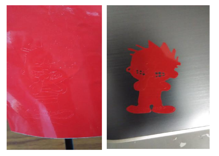
This time I used Vinyl cutting machine. I chose to cut a cartoon character, so I bitmapped it using Inkscape software.
After completion of our design and save it to .png format or .svg format (my design saved in .svg format). Then go to terminal.
type:
"fab" - Enter
Select the i/p format (.svg file).
Select the o/p process (Roland vinyl cutter).
Select the workflow (make_svg_camm).
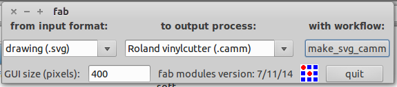
Select top first "vinyl".
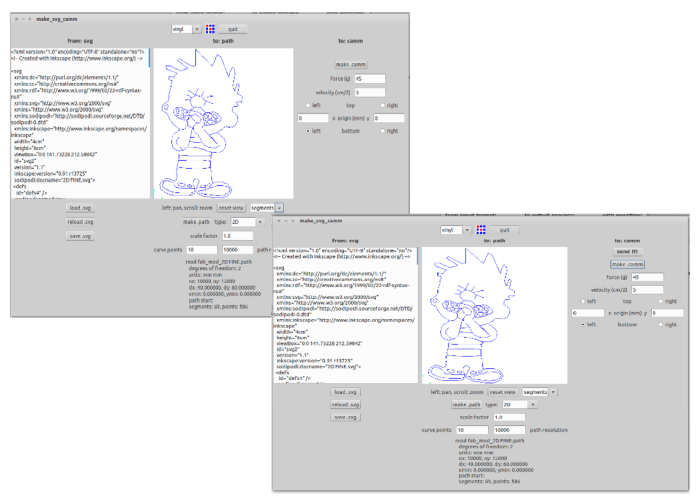
Stpe 1: To click the "load.svg" button and select our project work(.svg).
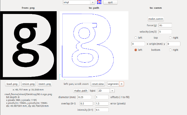
Stpe 2: To click the "make.path" button and view type select "segments".
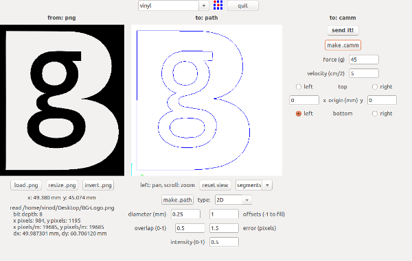
Stpe 3: To click the "make.camm" button and the project job "send it" to the vinyl cutter.
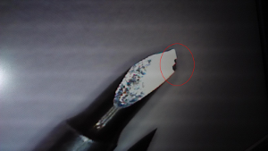
I printed my design through vinyl cutter. I got the fine print. Peal off the print and I pasted it on my Laptop cover.
Download My cartoon Design Files