
Introduction
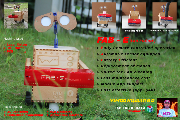
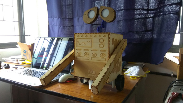
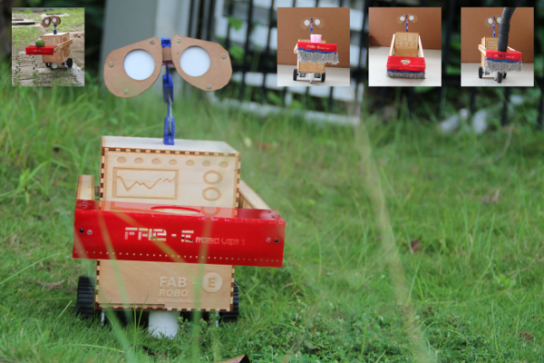
For my final project I decided to make a robot which can be usefull for Fablab cleaning. In my graduation days I got inspired from the movie Wall-E, So I thought to give looks of my robot similar to Wall-E, finally I borrowed "E" from Wall-E and attached to FAB to create Fablabs own FAB-E robot. This is a dual-mode robot that can be operated manually using an RF-based remote control and also can move automatically by sensing the obstacles. The robot has some inbuilt intelligence to avoid obstacles by changing its path using IR sensors. We used FAB-E in our fab lab, for clean shopbot dusts and cleaning the floor. It is a multipurpose robot which serves as
1. Transport the items.
2. Vacuum clean the floor.
3. Mopes the floor.
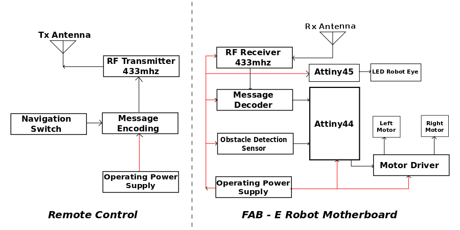
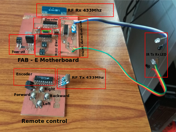
The figure shows that the block diagram of FAB - E Robo. It is an ATtiny - based dual-mode robot. When a button is pressed in the remote, the corresponding code is transmitted through RF transmitter. At the receiver end, this transmitted signal is received and decoded. The MCU unit compares the received code and drives the motors corresponding to the code received. Obstacle detectors detect any object in the way and intimate the microcontroller.
Circuit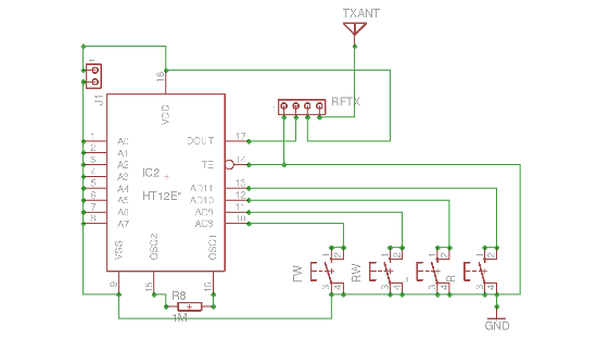
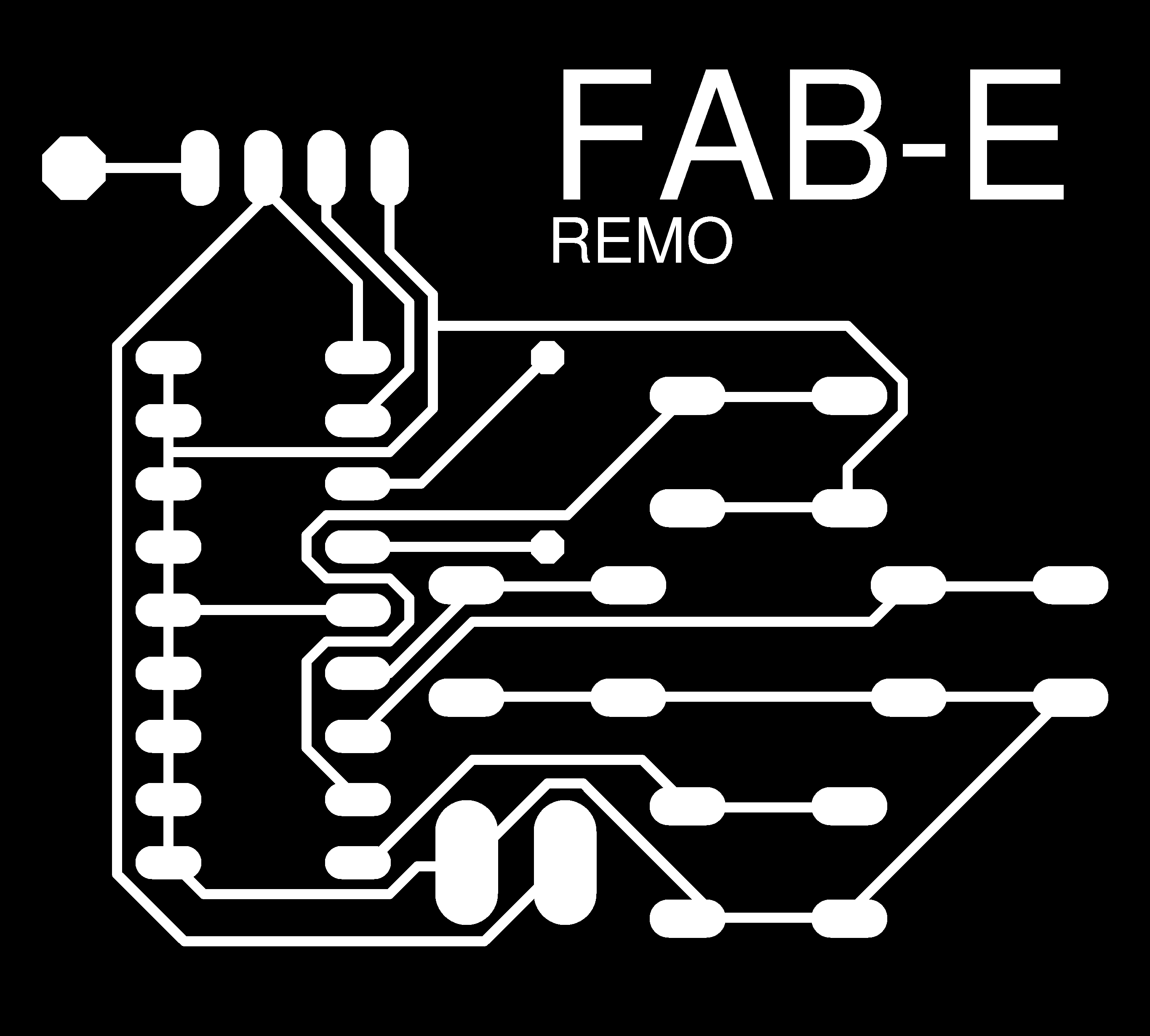
Remote
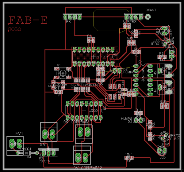
It is built around encoder IC HT12E (IC2), 433MHz RF transmitter module (RFTX) and a few discrete components. Switches FW, RW, L and R are interfaced with AD8 through AD11 of encoder IC2 for forward (FWD), reverse (REV), left (LEFT) and right (RIGHT) motions, respectively. Resistor R8 is connected between oscillator pins 15 and 16 to set the transmitter frequency. IC2 is permanently enabled for transmission by connecting its TE pin (pin 14) to ground.
When any switch, say FW, is pressed, the corresponding data is serially transmitted from DOUT pin (pin 17) through the RF transmitter module. A 9V battery is used to power the circuit.
FAB - E Robot
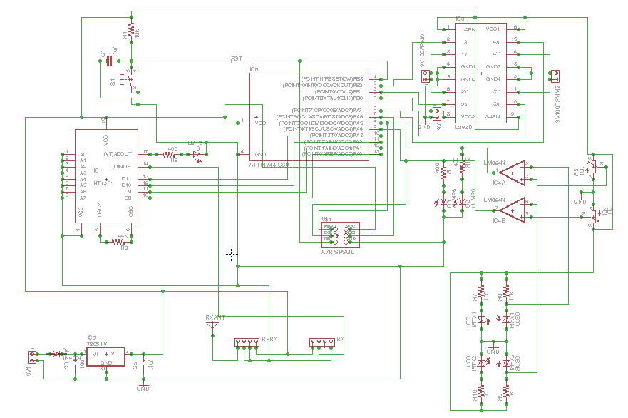
It comprises an RF receiver module, decoder HT12D (IC1), microcontroller ATtiny44 (IC6) and ATtiny45, operational amplifier LM324 (IC4A & B), motor driver L293D (IC3), regulator 7805 (IC5) and a few discrete components.
Data transmitted from the remote is received by the RF receiver module and further decoded by IC1. Decoded data is fed to pins PA0 through PA3 of microcontroller IC6. Identical addresses are selected for the encoder and the decoder by shorting them to ground. Output pins PB0 through PB3 of the microcontroller are fed to IN1 through IN4 of driver IC3 to drive motors M1 and M2, respectively. Enable pins EN1 (pin 1) and EN2 (pin 9) are kept high for always-enabled output.
Regulator IC5 provides 5V regulated supply. 9V battery supply is directly connected to pin 8 of motor driver IC3. Two IR transmitter-receiver pairs are used for obstacle detection. Presets VR1 and VR2 are used to set the reference voltage for the two operational amplifiers in IC4A & B.
When the robot reaches close to an obstacle, the reflected IR beam is detected. Voltage at the inverting pins of operational amplifiers goes lower than the reference voltage and their outputs go high. The same is indicated by D3 and D2. Output pins 1 and 7 of IC4A & B are connected to pins PA5 and PA4 of microcontroller IC6. The microcontroller controls the motor corresponding to the data received from the transmitter and obstacle detection system.
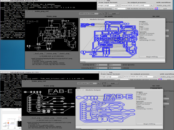
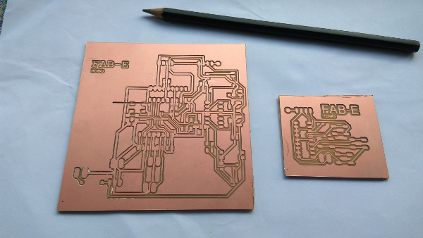
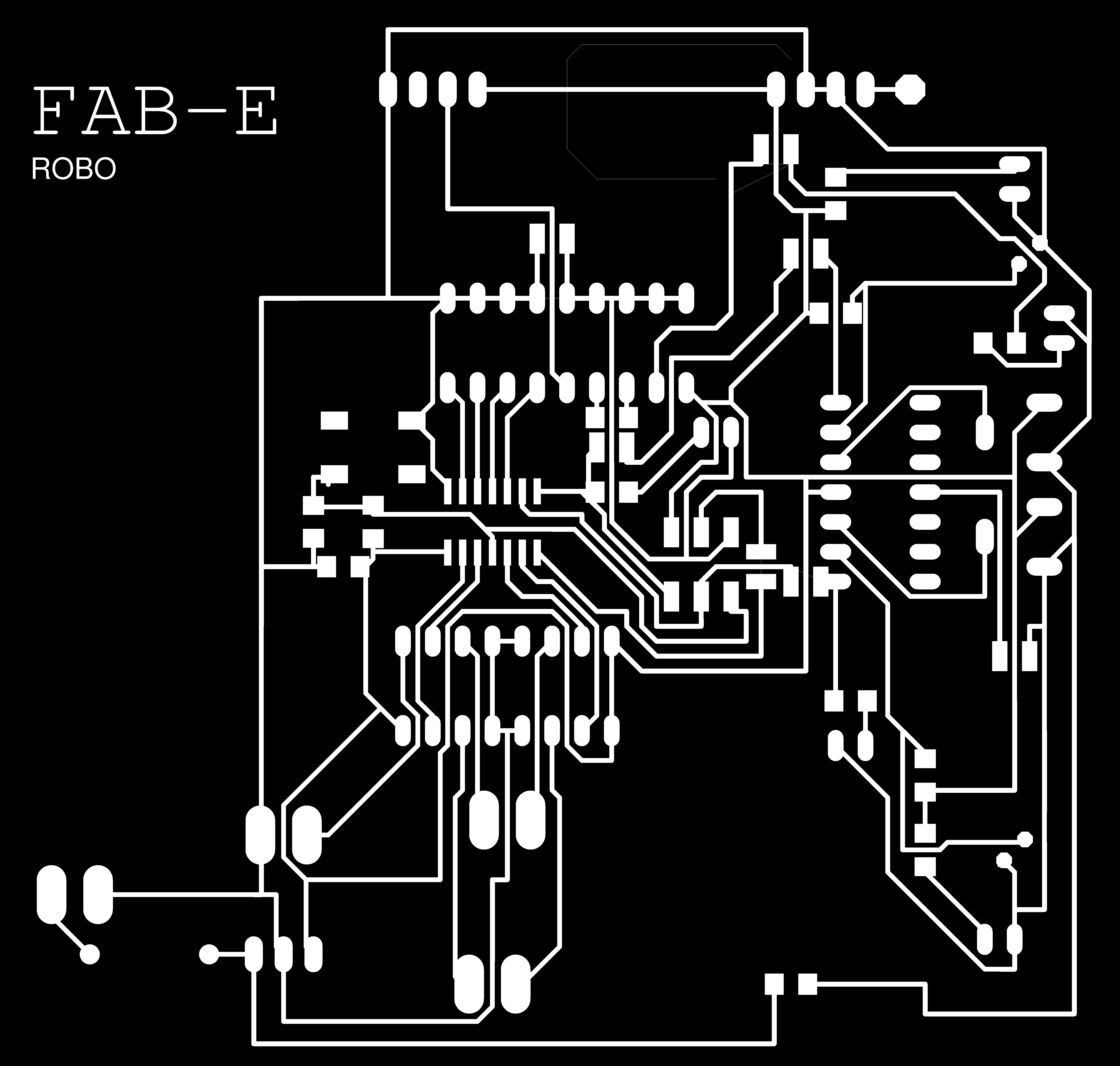
Next I start to mill my PCB design file to PCB milling machine.
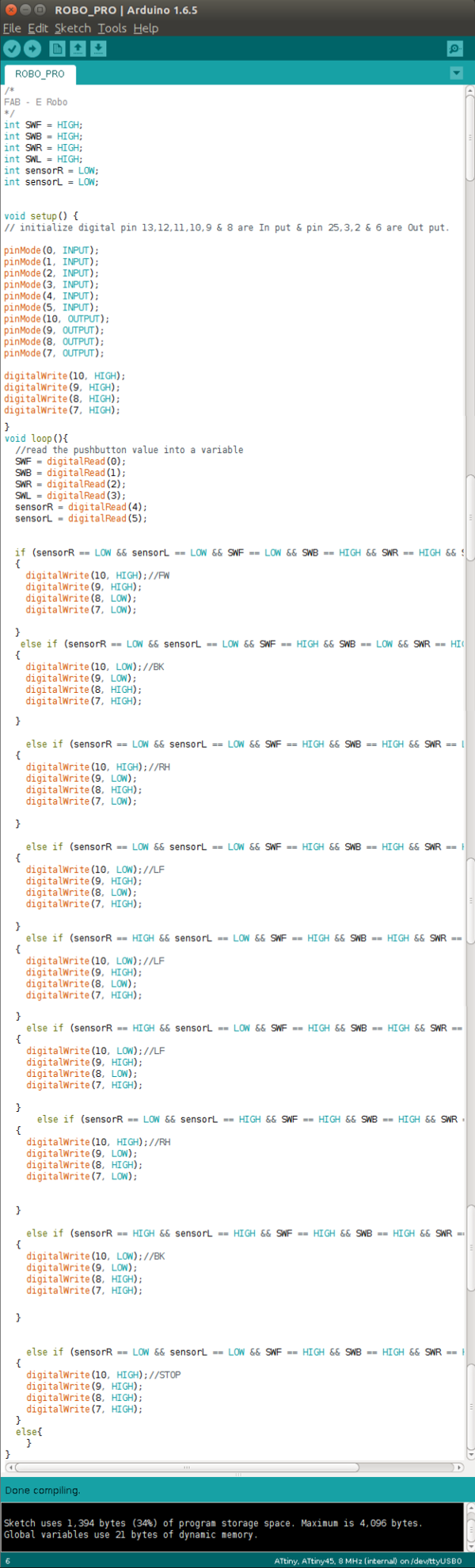
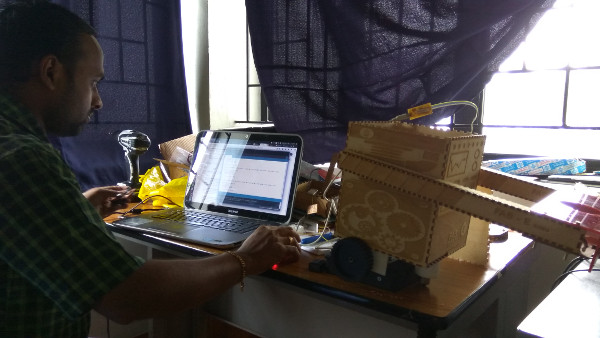
After complete my project circuit board I started to code the attiny.
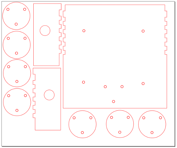
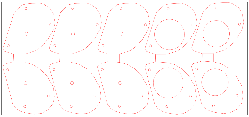
Making Robot Body
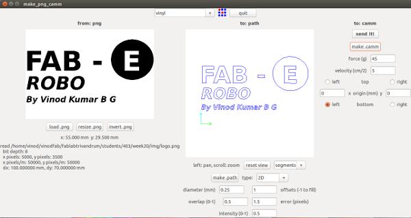
Design Robot body, head, hand and base using inkscape and rhinoceros Software and machine used 3D printer and laser cutter.

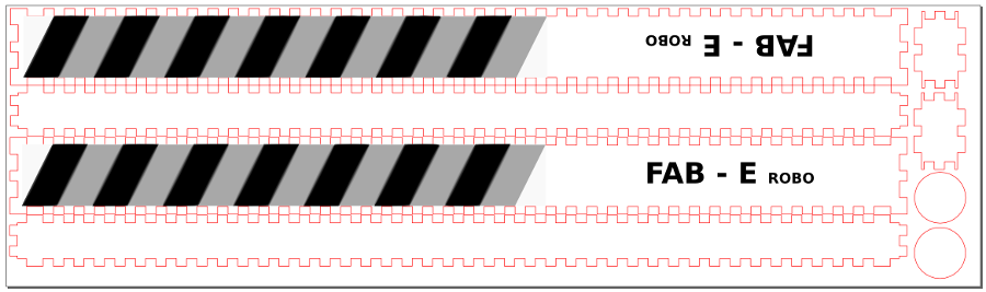
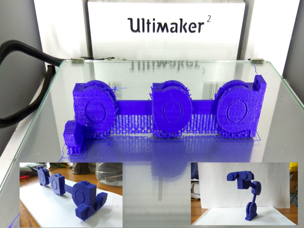
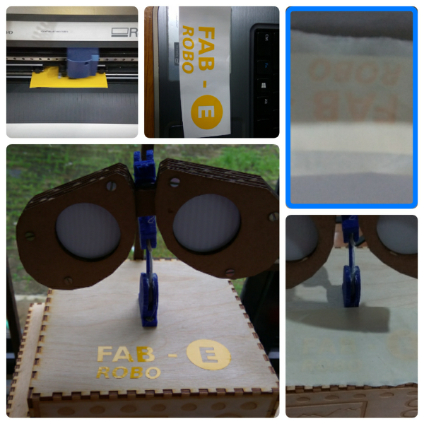
Finally I assembled all the parts togather, I got a wonderful FAB - E Robot.
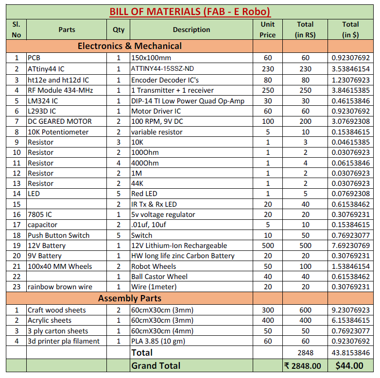
Download the Bill of Materials:
License
This project under license by MIT License (MIT).
Copyright (c) 2016 vinod@startupmission.in