Assignment
- Add an output device to a microcontroller board you've designed and program it to do something
- Demonstrate workflows used in circuit board design and fabrication.
- Implement and interpret programming protocols.
- Described your design and fabrication process using words/images/screenshots.
- Explained the programming process/es you used and how the microcontroller datasheet helped you.
- Outlined problems and how you fixed them.
- Included original design files and code.
This week's assignment is to built a output device, I choose RGB LED project. My plan is to make a "Police beacon Lights" using ATtiny45. This light is blinked only Two color(Red and Blue) in a single RGB LED. First cycle Red LED blink that time Blue LED OFF, 2nd cycle Red LED OFF that time Blue LED blink. This function run at four time's, next the tow LED's are blink for a short time.
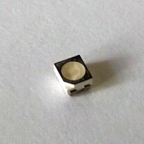
First I design the circuit in Eagle software. It contains ATtiny 45 one RGB LED three resistors, ISP connector and voltage regulators etc. I designed it in eagle and is shown below.
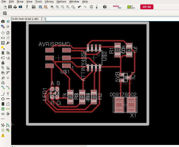
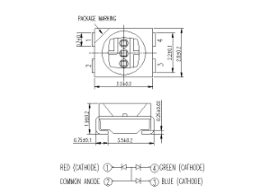
RGB LEDs consist of one red, one green, and one blue LED. By independently attenuating each of the three, RGB LEDs are capable of producing a wide color gamut.
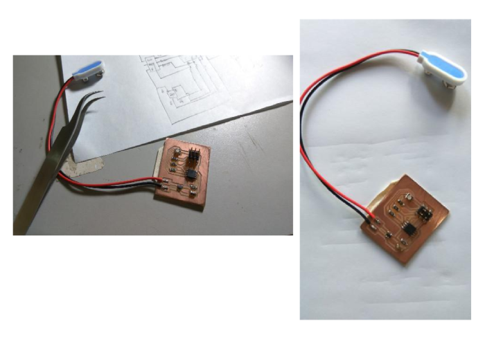
After completion of circuit design Mill and cut the PCB with Modela CNC. The steps for the fabrication and setting up are same which I have done in the previous weeks.


Next I started soldering the PCB with respect to the schematic attached above. After soldering I ensured there is no shorting between tracks with the help of magnifier. Next we have to programm it using fab ISP. Actually I made two programms one is a police beacon light which the combination of red and blue LED is used. In the other one I made simple RGB light with different combinations.
In this part I have written the programm for police beacon light usid arduino IDE. The logic used is simple, switching the blue and red LED with different delays in 4 cycles. The net effect will be like a police beacon light.
/*
Turns ON an Police car light using RGB LED
*/
// the setup function runs once when you press reset or power the board
void setup() {
// initialize digital pin 6 & 7 as an output.
pinMode(PB1, OUTPUT);
pinMode(PB2, OUTPUT);
}
// the loop function runs over and over again forever
void loop() {{
digitalWrite(PB1, LOW); // red
digitalWrite(PB2, HIGH); // blue ON
delay(50);
digitalWrite(PB1, HIGH); // red ON
digitalWrite(PB2, LOW); // blue
delay(50);
digitalWrite(PB1, LOW); // red
digitalWrite(PB2, HIGH); // blue ON
delay(50);
digitalWrite(PB1, HIGH); // red ON
digitalWrite(PB2, LOW); // blue
delay(50);
digitalWrite(PB1, LOW); // red
digitalWrite(PB2, HIGH); // blue ON
delay(50);
digitalWrite(PB1, HIGH); // red ON
digitalWrite(PB2, LOW); // blue
delay(50);
digitalWrite(PB1, LOW); // red
digitalWrite(PB2, HIGH); // blue ON
delay(50);
digitalWrite(PB1, HIGH); // red ON
digitalWrite(PB2, LOW); // blue
delay(50);
digitalWrite(PB1, HIGH); // red ON
digitalWrite(PB2, HIGH); // blue ON
delay(20);
digitalWrite(PB1, LOW); // red
digitalWrite(PB2, LOW); // blue
delay(20);
digitalWrite(PB1, HIGH); // red ON
digitalWrite(PB2, HIGH); // blue ON
delay(20);
digitalWrite(PB1, LOW); // red
digitalWrite(PB2, LOW); // blue
delay(20);
digitalWrite(PB1, HIGH); // red ON
digitalWrite(PB2, HIGH); // blue ON
delay(20);
digitalWrite(PB1, LOW); // red
digitalWrite(PB2, LOW); // blue
delay(20);
digitalWrite(PB1, HIGH); // red ON
digitalWrite(PB2, HIGH); // blue ON
delay(20);
digitalWrite(PB1, LOW); // red
digitalWrite(PB2, LOW); // blue
delay(20);
}}
Extra Assignment - 1
Program for RGB LightIn this I used the logic normal RGB leds red green blue lights are glowing sequencially. Here I am programmed such that different color combination is also possibe in this. One thing is that there is no need for making a new board, just we change the program we can use the same board for different purpose.
/*
Turns ON an RGB LED on for two second
*/
void setup() {
// initialize digital pin 5,6 & 7 as an output.
pinMode(PB0, OUTPUT);
pinMode(PB1, OUTPUT);
pinMode(PB2, OUTPUT);
}
// the loop function runs over and over again forever
void loop() {
digitalWrite(PB0, HIGH); // green
digitalWrite(PB1, LOW); // red
digitalWrite(PB2, LOW); // blue
delay(200);
digitalWrite(PB0, LOW); // green
digitalWrite(PB1, HIGH); // red
digitalWrite(PB2, LOW); // blue
delay(200);
digitalWrite(PB0, LOW); // green
digitalWrite(PB1, LOW); // red
digitalWrite(PB2, HIGH); // blue
delay(200);
digitalWrite(PB0, HIGH); // green
digitalWrite(PB1, HIGH); // red
digitalWrite(PB2, LOW); // blue
delay(200);
digitalWrite(PB0, LOW); // green
digitalWrite(PB1, HIGH); // red
digitalWrite(PB2, HIGH); // blue
delay(200);
digitalWrite(PB0, HIGH); // green
digitalWrite(PB1, LOW); // red
digitalWrite(PB2, HIGH); // blue
delay(200);
digitalWrite(PB0, HIGH); // green
digitalWrite(PB1, HIGH); // red
digitalWrite(PB2, HIGH); // blue
delay(200);
}
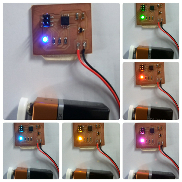
Output of RGB Light Program
Download My design files :
Beacon light PCB milling PNG file
Beacon light PCB cutting PNG file
Download the program files :
Beacon lightProgram file (Text)