Week 3 Assignment: design, make, and document a parametric press-fit construction kit
Go back HOME
This week's assignment was about understanding how to create a parametrically-designed "press-fit construction kit" --> where the pieces of the "kit" in question fasten to each other by friction after the parts are "pushed together", rather than by another means of fastening like nailing, stapling or screwing together the pieces. See the below visuals that illustrates how the press-fit is formed:
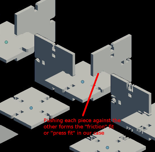
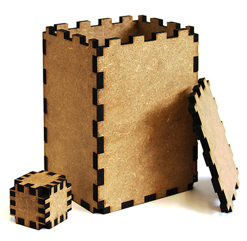 Picture Source: academy.cba.mit.edu Picture Source: http://www.alexrulkens.com/projects/magicbox
An important aspect of this assignment was to use a CAD package that had parametric design functionalities -- which therefore meant that we could apply "rules" or change parameters such as the dimensions or sizing of our design depending on various constraints introduced during the iteration process. E.g. Suppose we needed to apply the same design but on a different raw material as opposed to the material the design was originally created for.
Along with my classmates, I checked out the various options I had available for utilizing Parametric Modeling functionalities within a CAD package:
- Antimony = Although this was initially suggested as the primary choice for the assignment by the teaching staff; I found it quite arduous to install and even more difficult to "draw" with.
- Autodesk's 123D Make = I wasn't able to try its features in time to complete this assignment
- FreeCAD = I was under the assumption that this CAD package would do the job, it was free and easy to install on MacOSX so I was quite keen to show some success in generating a press-fit design -- however, I realized that the software was more suited to creating in 3D, and what I really needed for this assignment was to generate some kind of repeatable pattern using 2D drawing only. So I decided I would check out FreeCAD another day!
- Inkscape = Hesitantly, I reverted to Inkscape as the chosen software package to create my parametric 2D design :)
Although I was intending to create my 2D Model of my final project in Inkscape, at the last minute I changed my mind and used QCAD (see my Assignment 2 submission) and therefore didn't get the practice I thought I needed to complete this assignment. Luckily, I found a brilliant guide on how to create a press-fit design via the FabWiki created by FabLab Island --> http://wiki.fablab.is/wiki/Inkscape_how_to_make_a_pressfit_design
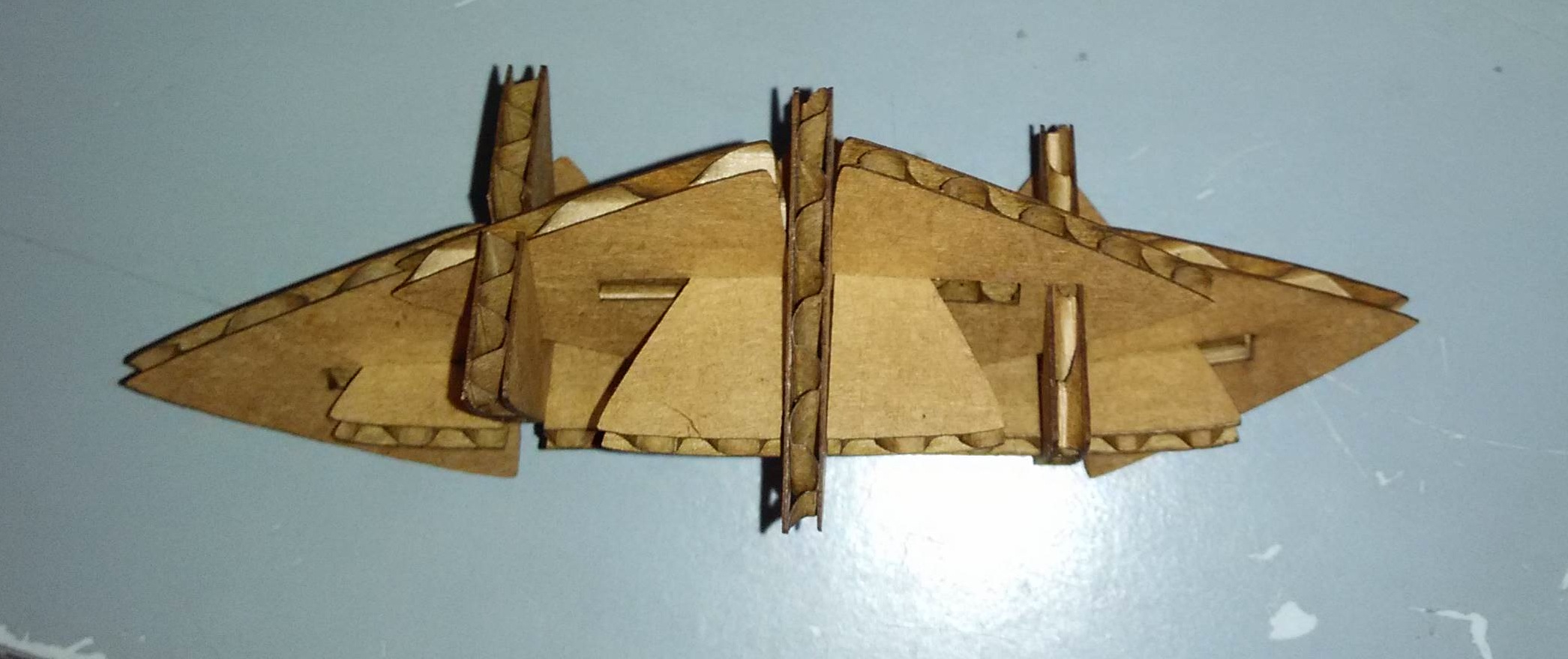
Creating my 2D shape to be laser cut
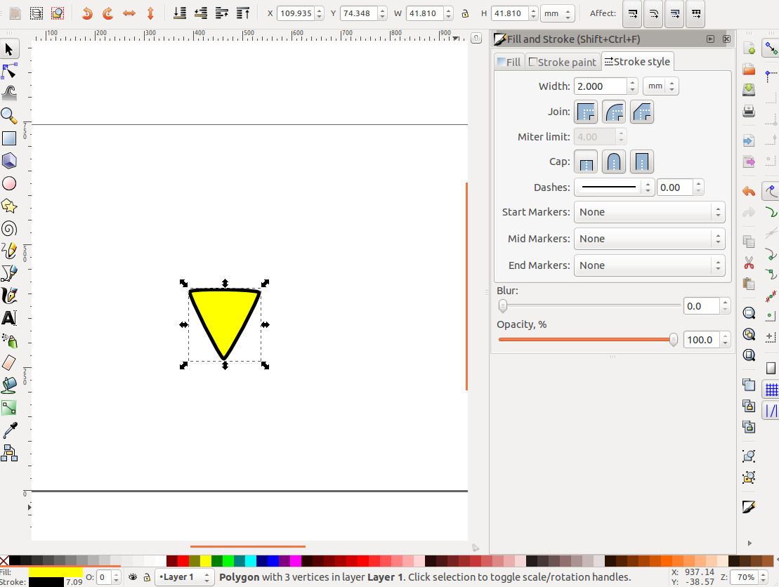
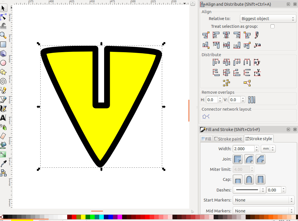
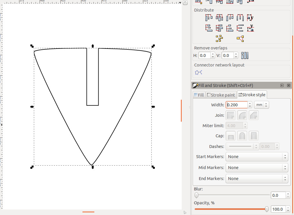
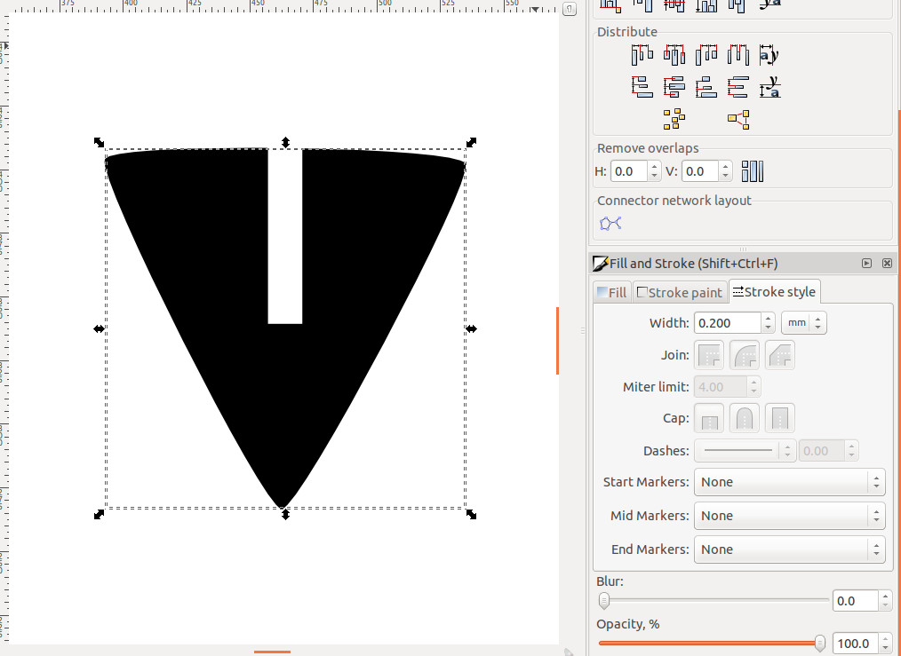
- I drew a Triangle shape in Inkscape, applying a "round joint" on the corners in order Chamfer the edges for cutting. I also took into account the thickness of the line width and included it in the size of the overall width of my triangle
- My next step was to draw a smaller rectangle to serve as the "slot" for my 2D object, declaring the rectangle to have the same width as the thickness of the cardboard we plan to use to create our press-fit kit (2mm), center aligning it with respect to the (larger) triangle shape
- I subtracted the rectangle from the triangle which created the true "slot" and finished my 2D shape
- In order to account for the 0.2mm burn-away by the laser cutter, I modified the line width of my slotted triangle to 0.2mm
- I added 0.2mm to the overall line width by offsetting the line to the inside and got my final shape
- I then used the "Clone" command to clone my slotted triangle shape.
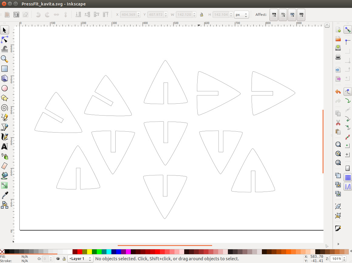
Please find my Inkscape 2D Shape (.svg) file here: Inkscape 2D Shape Model - Slotted Triangle
Laser Cutting my Slotted Triangle shape
- I opened up my slotted triangle file in Inkscape --> sent it to the Laser Cutter for processing:
Substeps followed:
- Pressed the "On" button for the Trotec Speedy 100 (Laser Cutter) device
- Ensured that the Exhaust System was enabled
- Focused the Laser Beam at the origin by Software (as opposed to manually focusing the beam)
- Loaded a 60cm x 30cm cardboard sheet on the bed of the Laser Cutter, lining the corner at the Origin
- Open up my slotted triangle file (.png) in Inkscape --> opened the Print dialog window and selected the Trotec Speedy 100 (Laser Cutter) as "printer"
- Upon opening up the Laser Cutter Job Control Application (TROTEC job Control) --> double clicked my "print job" from the queue --> this initiated the actual laser cutting itself
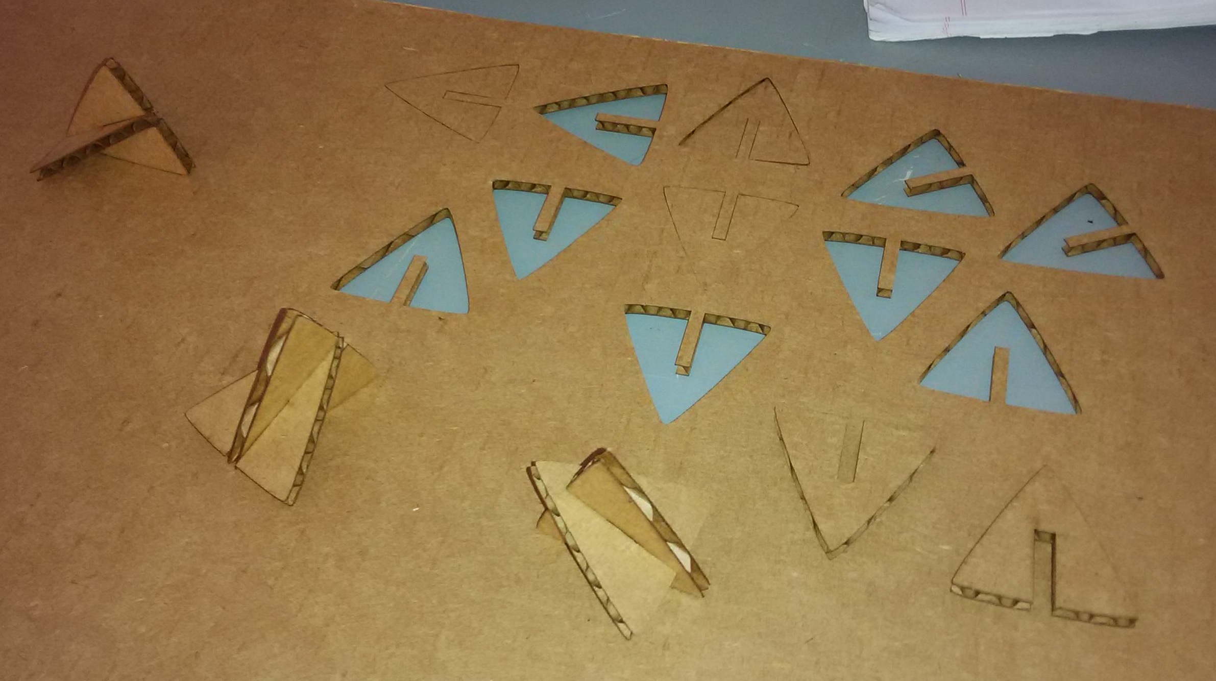
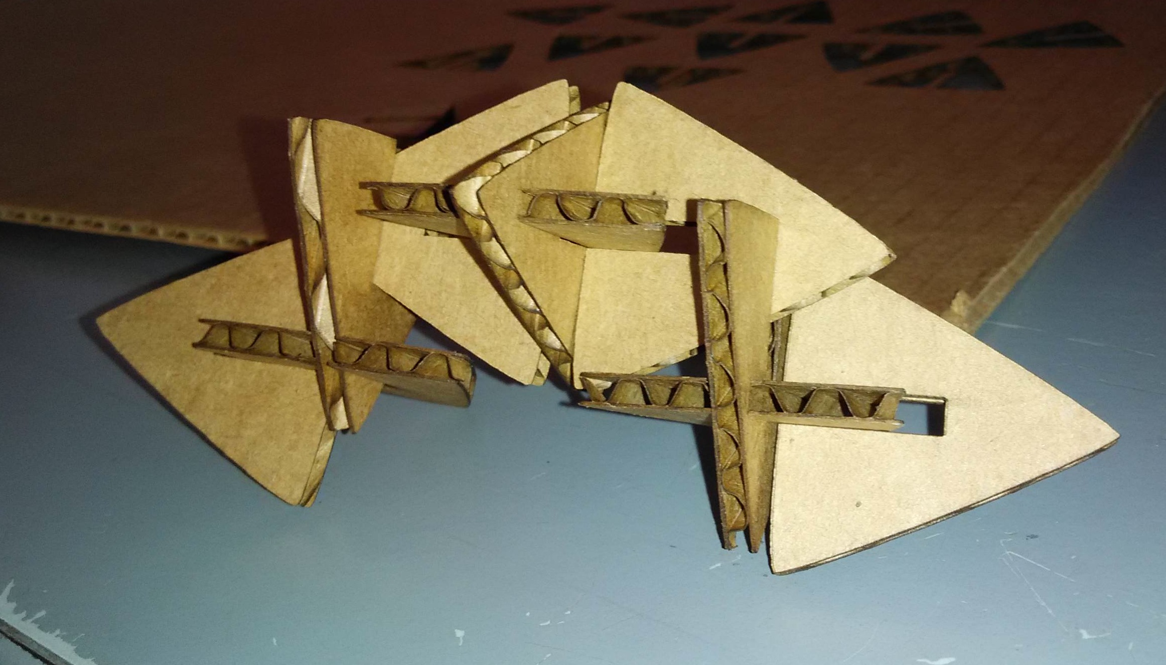
- Once cut, I tested to see if the Press-fit actually worked and that the cardboard pieces were being held together by friction:
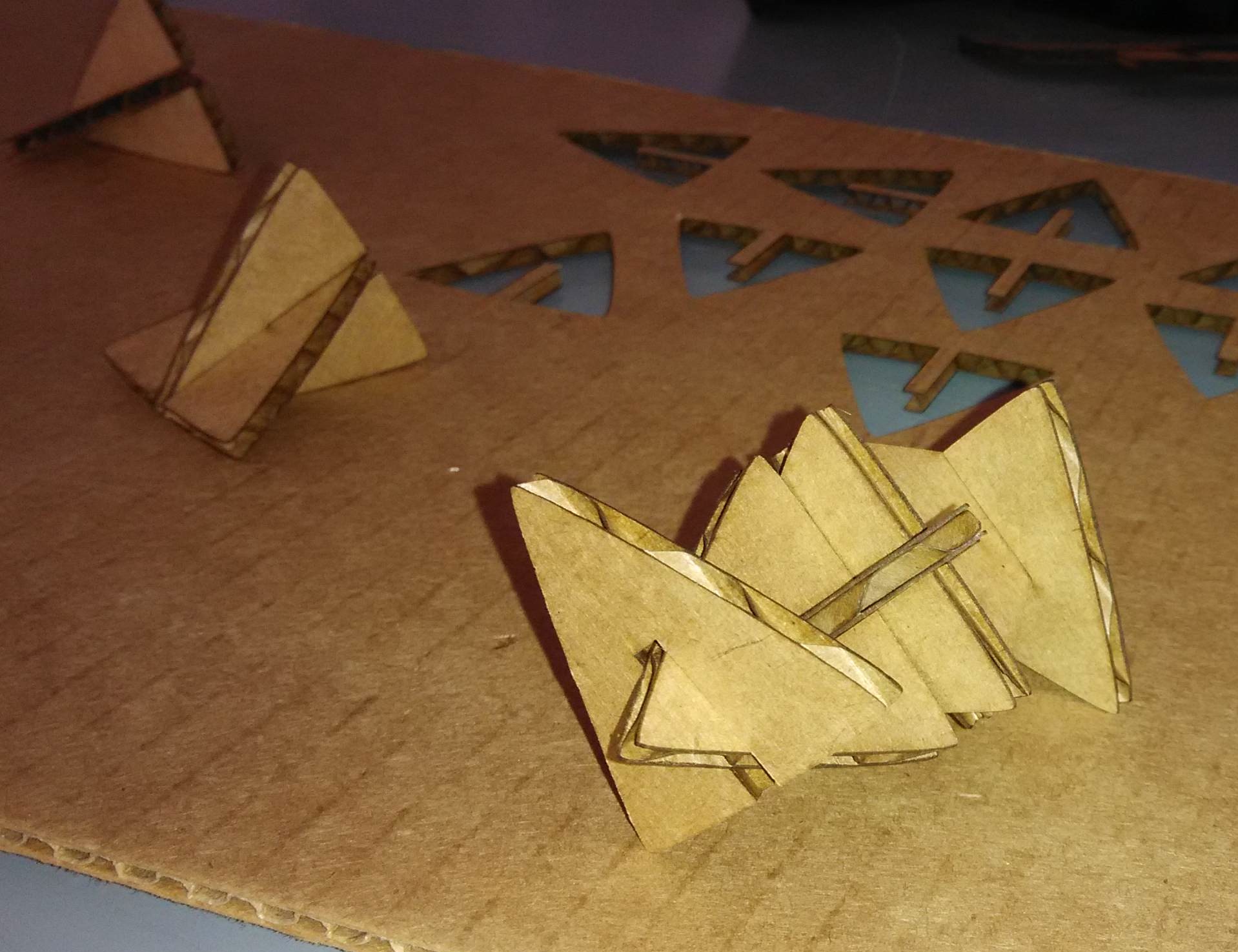
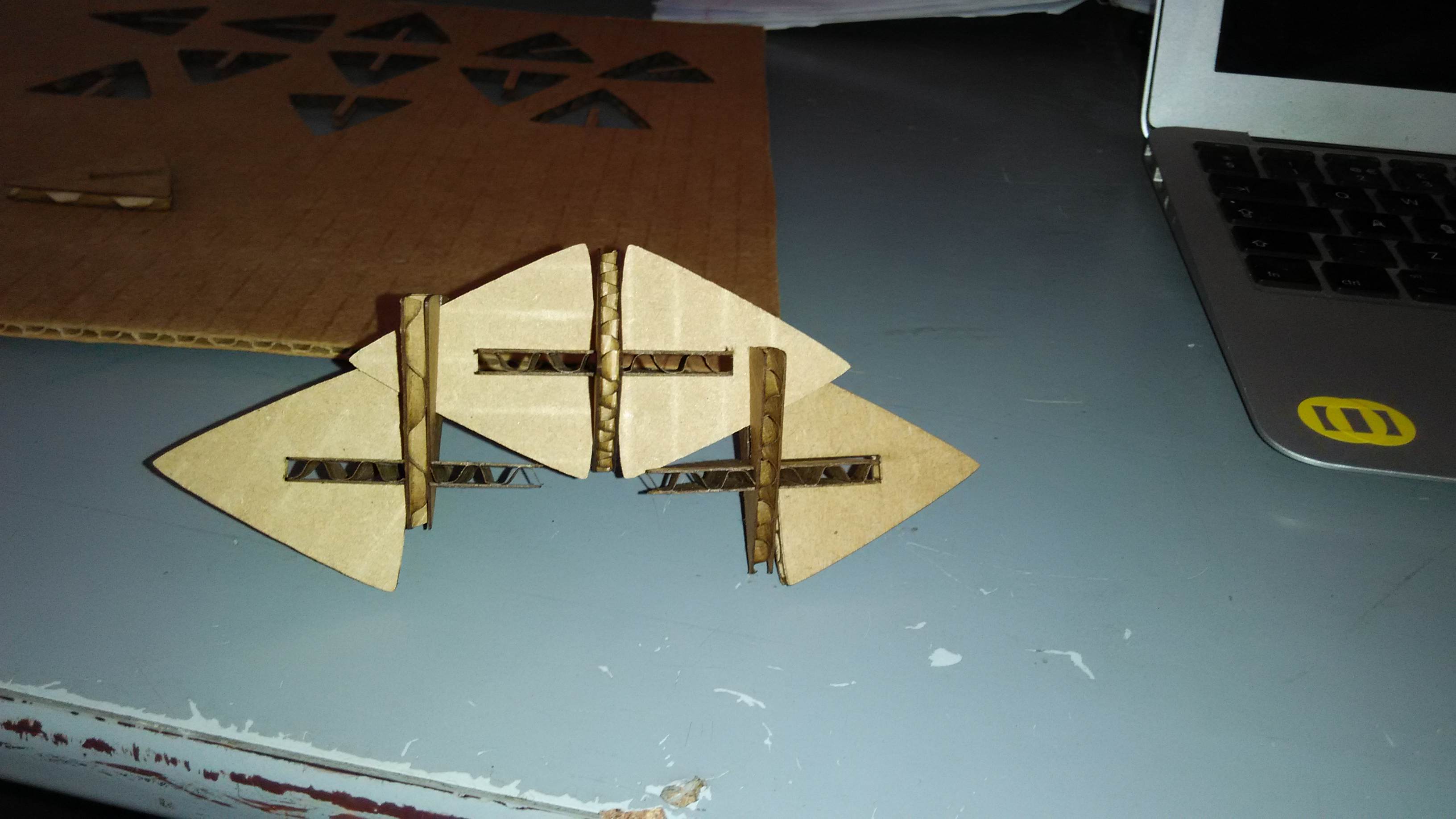
- It did! I created a mini-assembly of my slotted triangles as follows:
Using the Vinyl Cutter
Another part of Week 3 was getting exposure to using a Desktop-sized Vinyl Cutter. I liked the idea of making and "cutting" my own stickers, especially understanding how the stickers themselves would be able to be peeled away from their adhesive-surfaces.
At the Fab Lab Kerala, we have a Roland GX-24 (CAMM-1 servo Desktop Sign Maker)
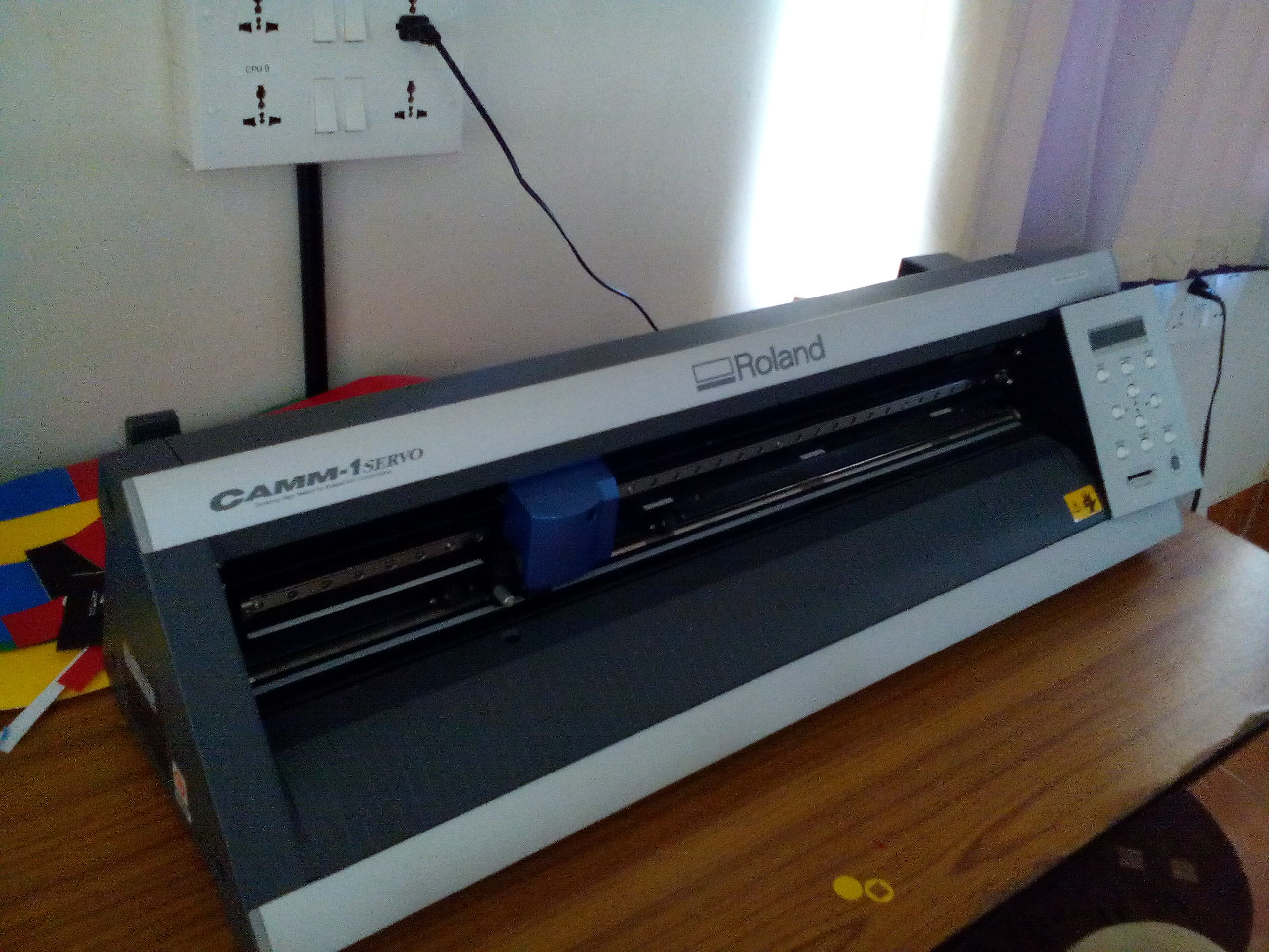
How I made a sticker using the Roland GX-24 Vinyl Cutter
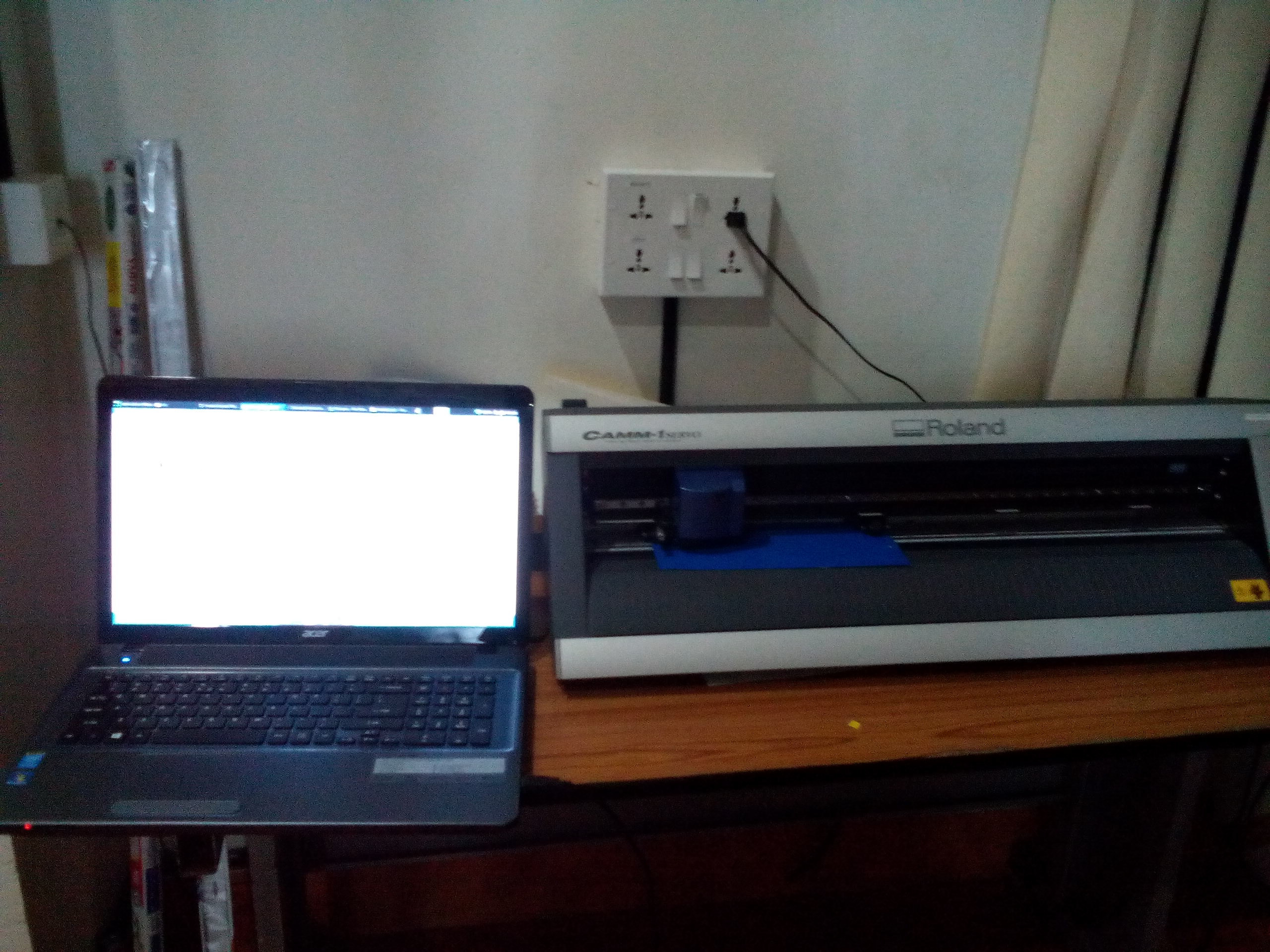
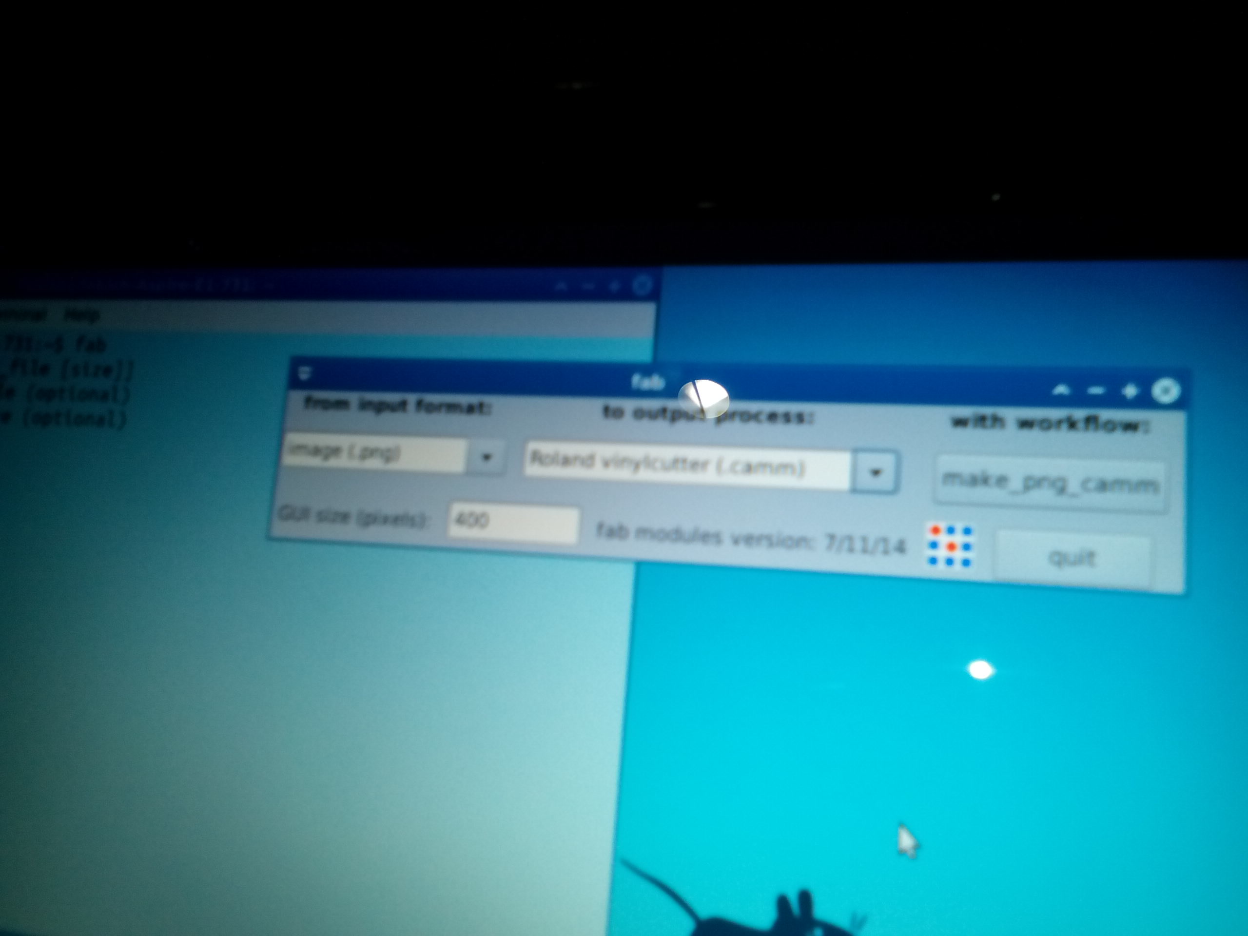
- Logging into the system to which the Vinyl Cutter was connected, I checked to see whether FabModules was installed
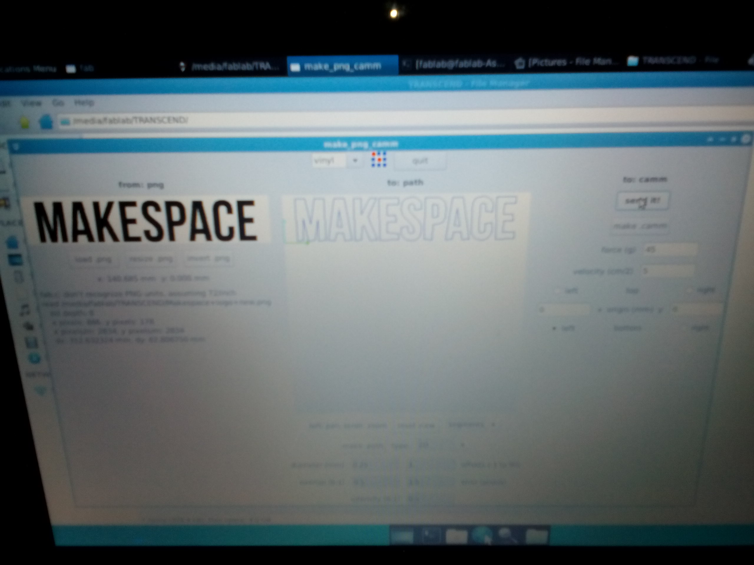
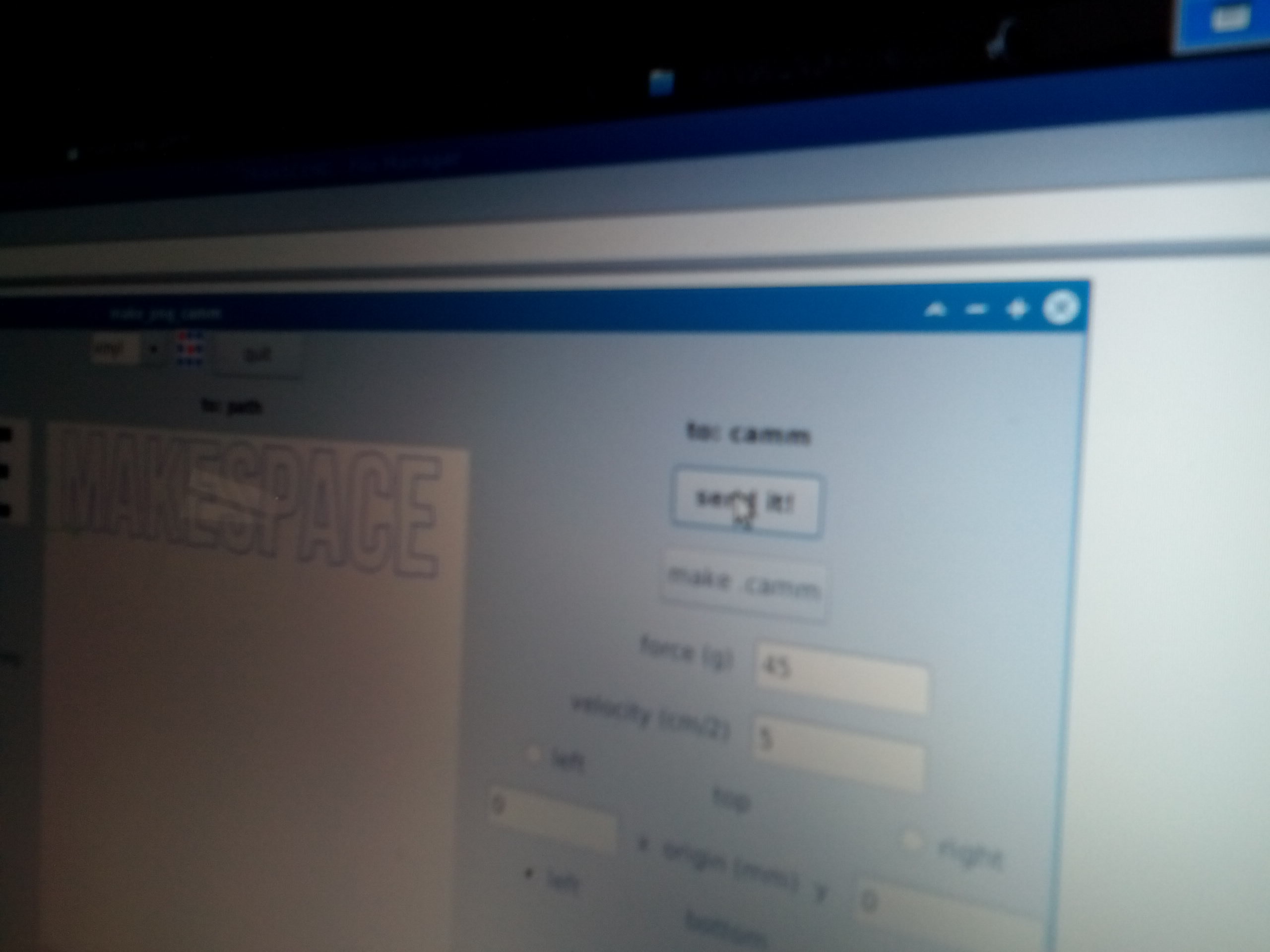
- Upon confirmation, I opened up the fab dialog window to input my sticker .png file with the following values:
- From Input Format = image(.png)
- To Output Process = Roland vinylcutter (.camm)
This generated the make_png_camm Workflow:
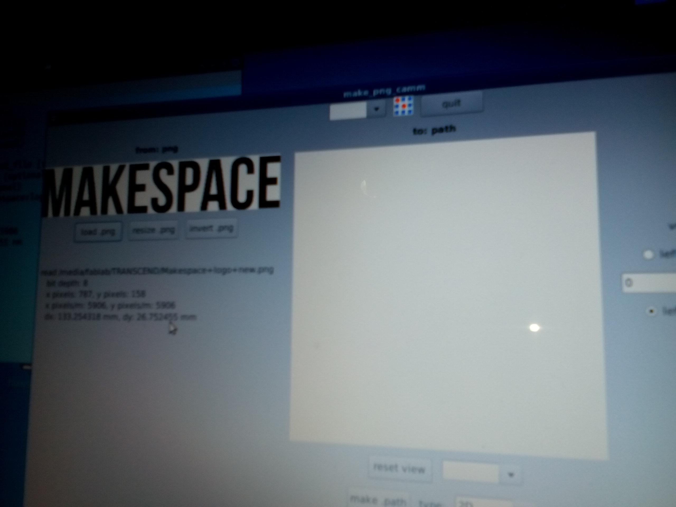
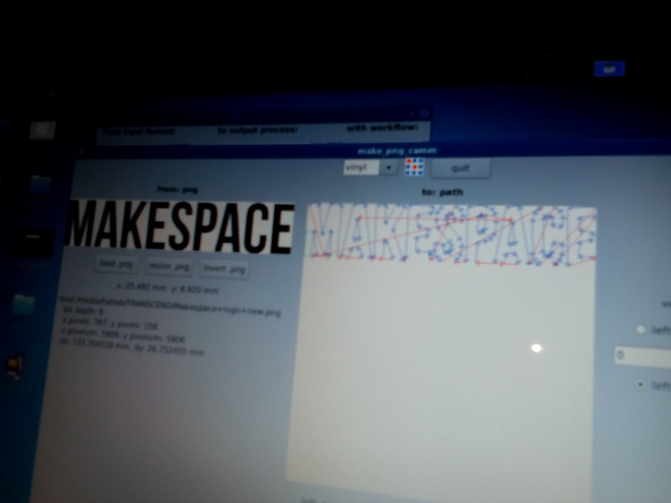
- Upon uploading my .png image under the make_png_camm dialog window, I chose "vinyl" under the drop down menu and generated the .camm file to send to the Vinyl Cutter by selecting the force (g) = 45 and the velocity (cm/s) = 5
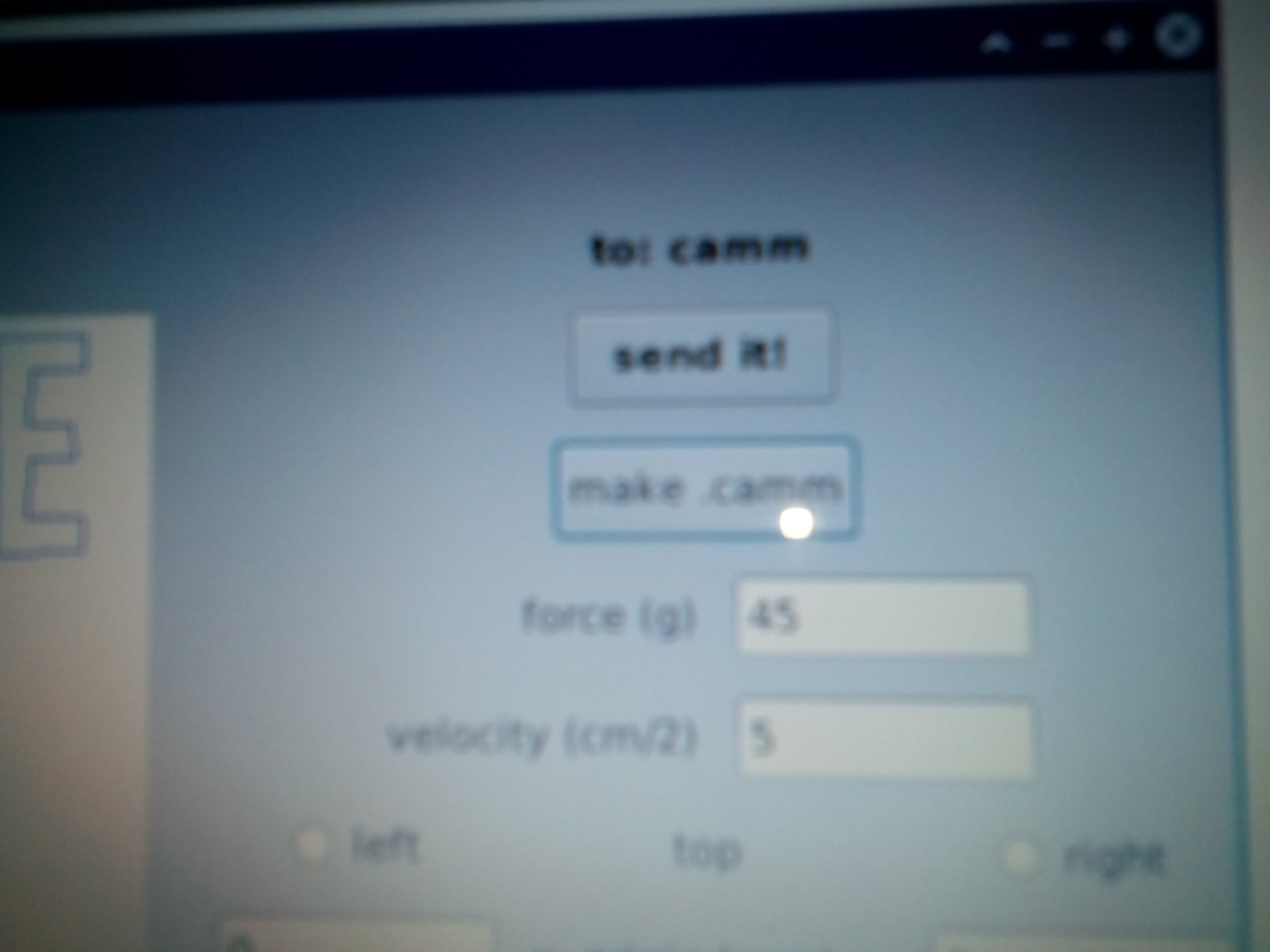
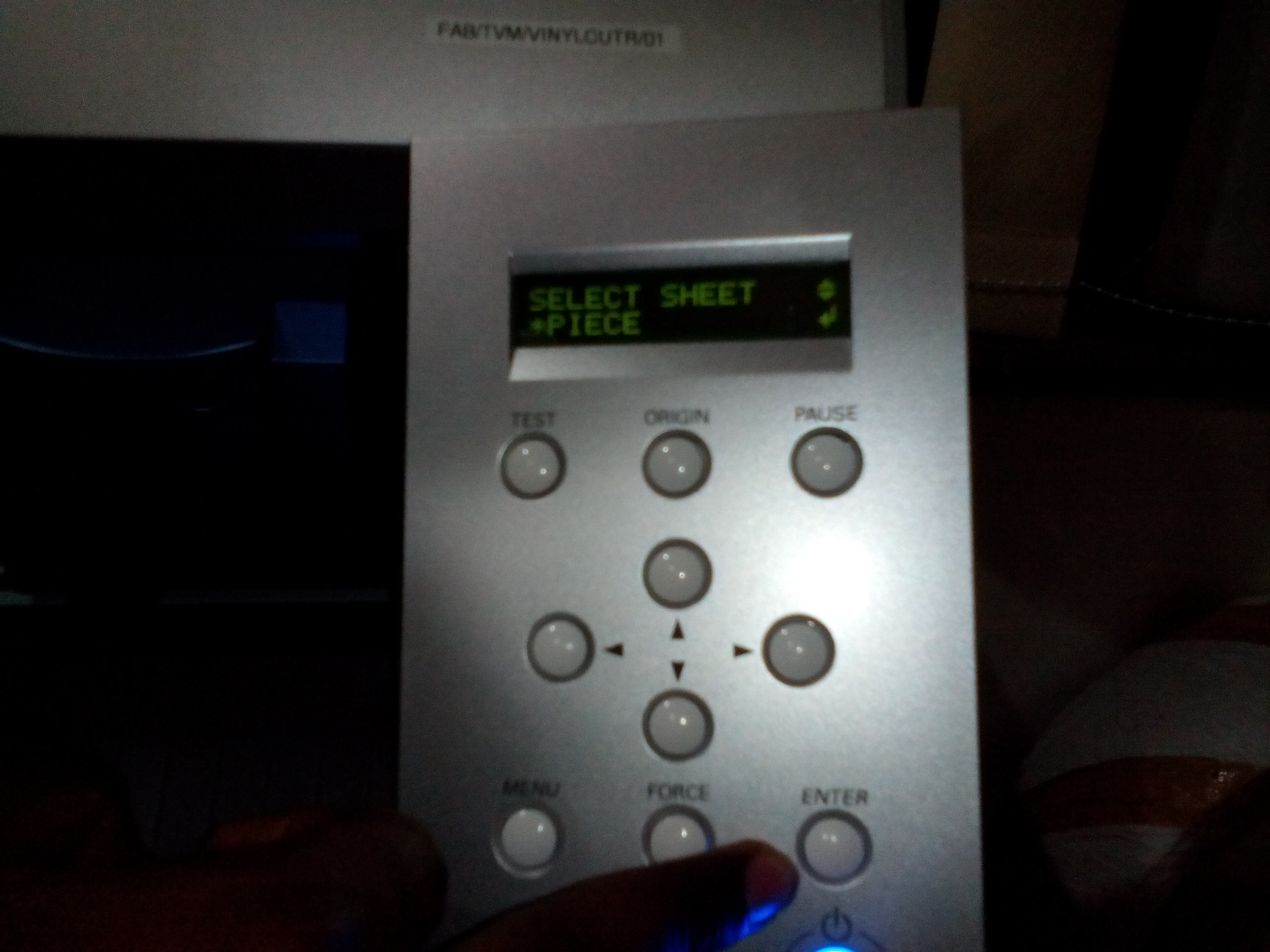
- I powered on the Vinyl Cutter, navigated the menu to choose the "Select Sheet *Piece" option, and loaded the sticker paper according to the origin line on the cutter
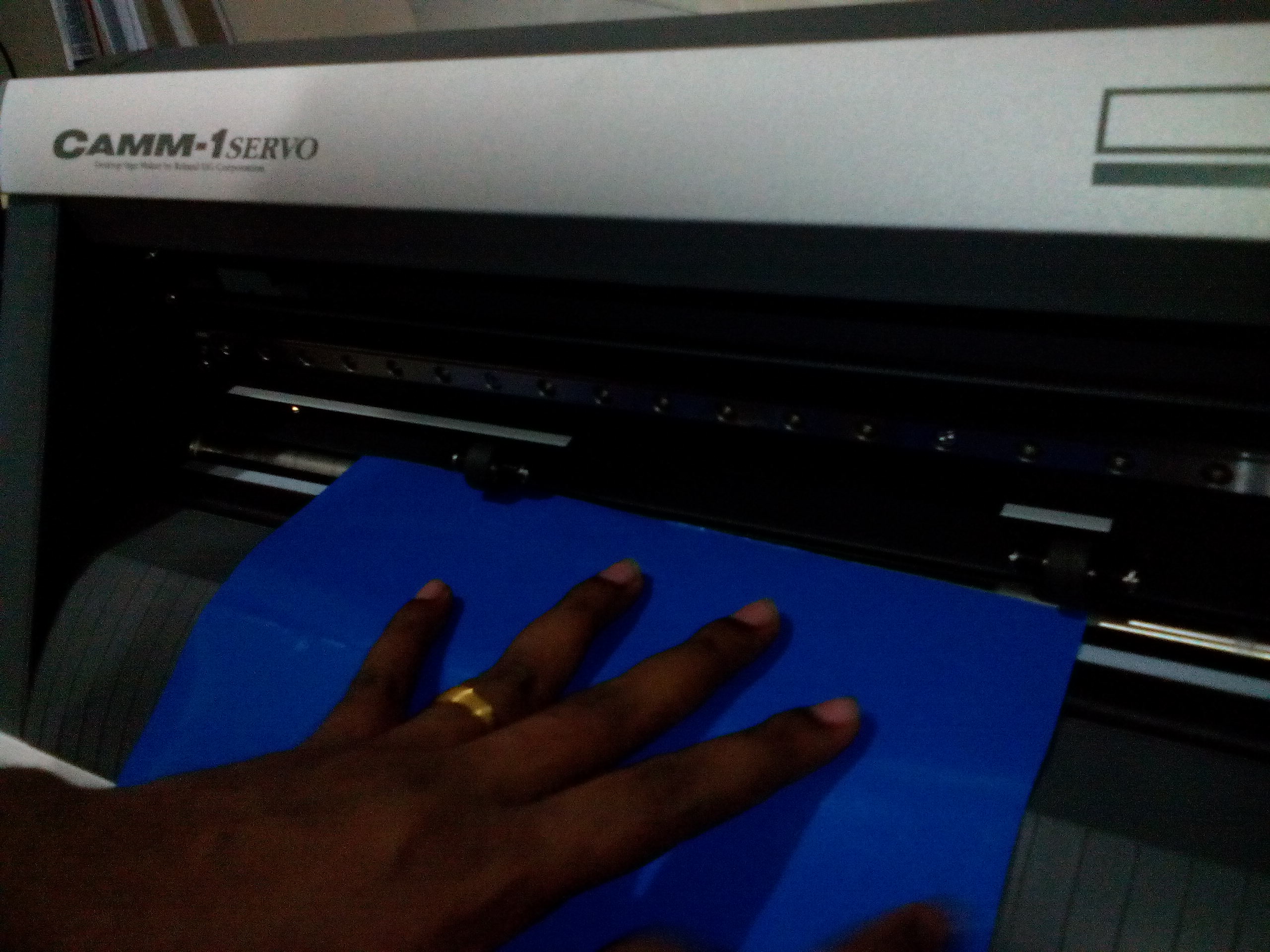
- I hit the "send it!" option under the make_png_camm dialog window and the Vinyl Cutter started "printing" (cutting, rather!) my sticker at a velocity of 2 cm/s and at a Force of 70gf
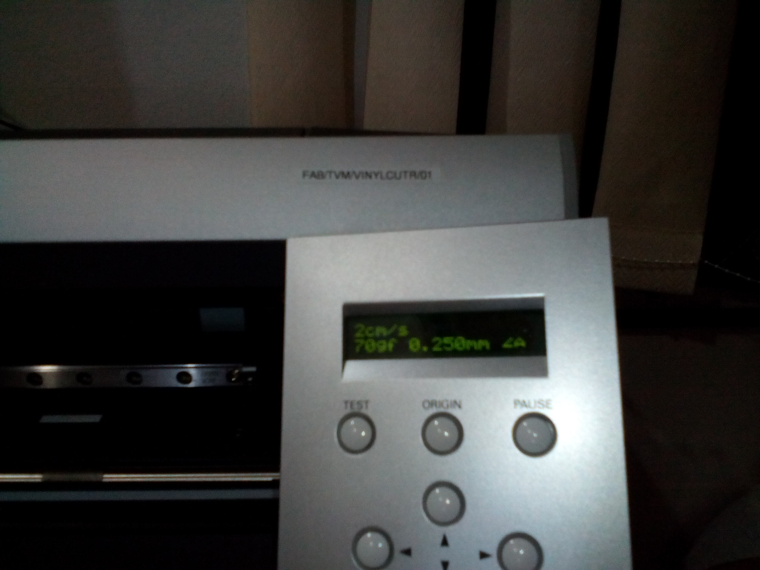
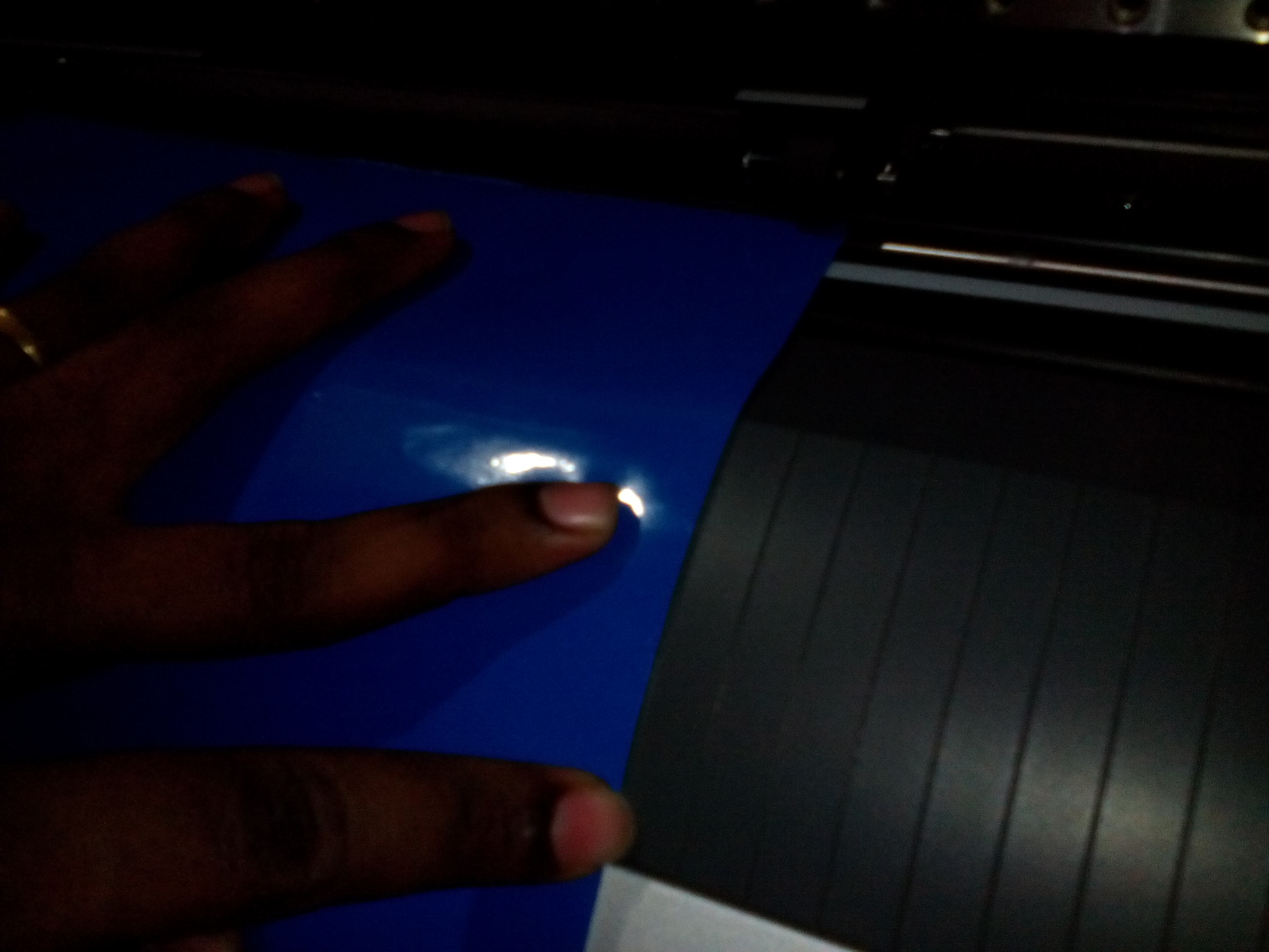
- Unfortunately, the sticker paper I was using wasn't broad enough, and I had not set the print parameters carefully enough to get my *entire* sticker printed according to the original dimensions. However, I was pleased that I was able to easily peel off my cut stickers and affix them on my FabAcademy notebook!
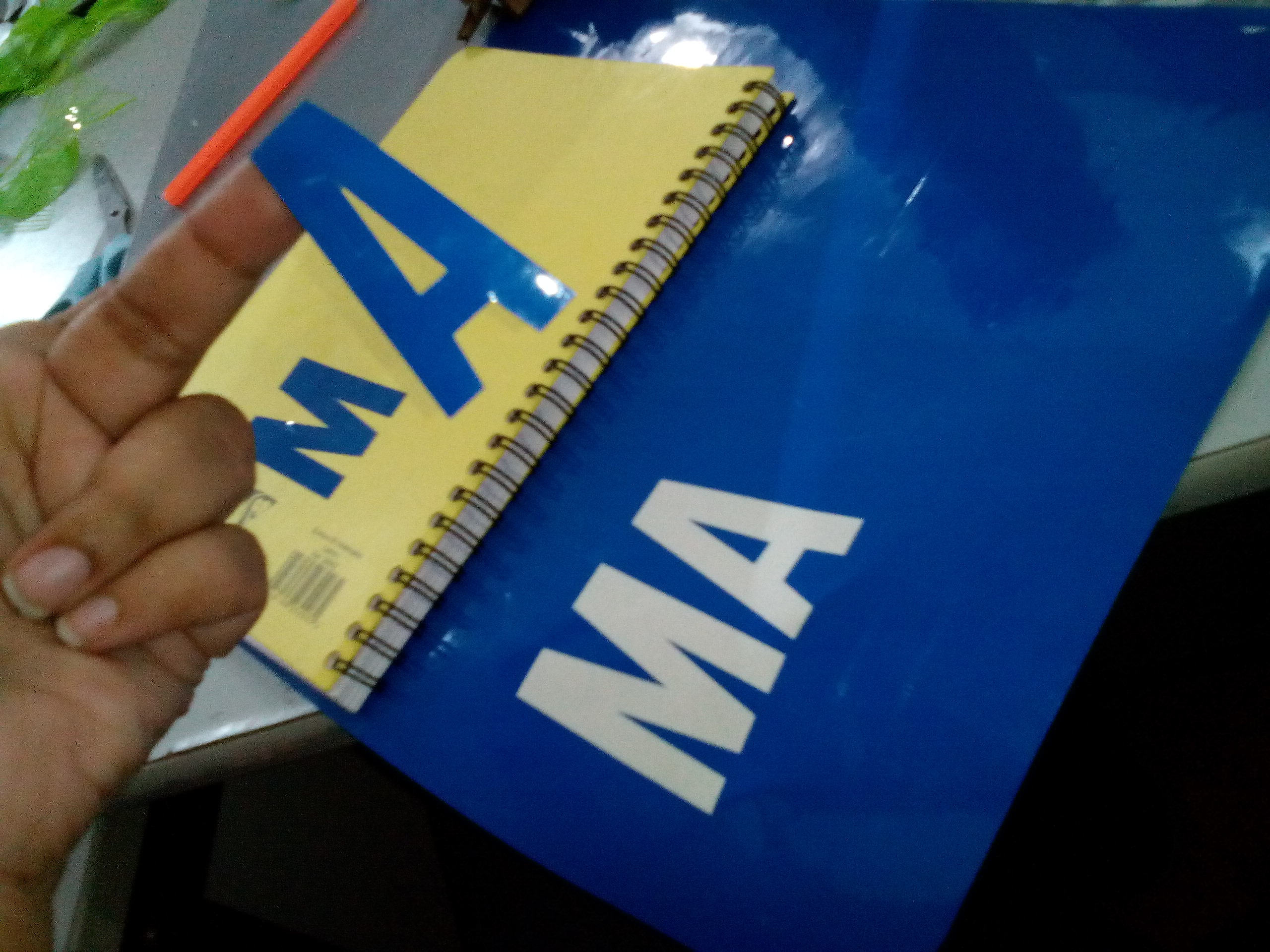
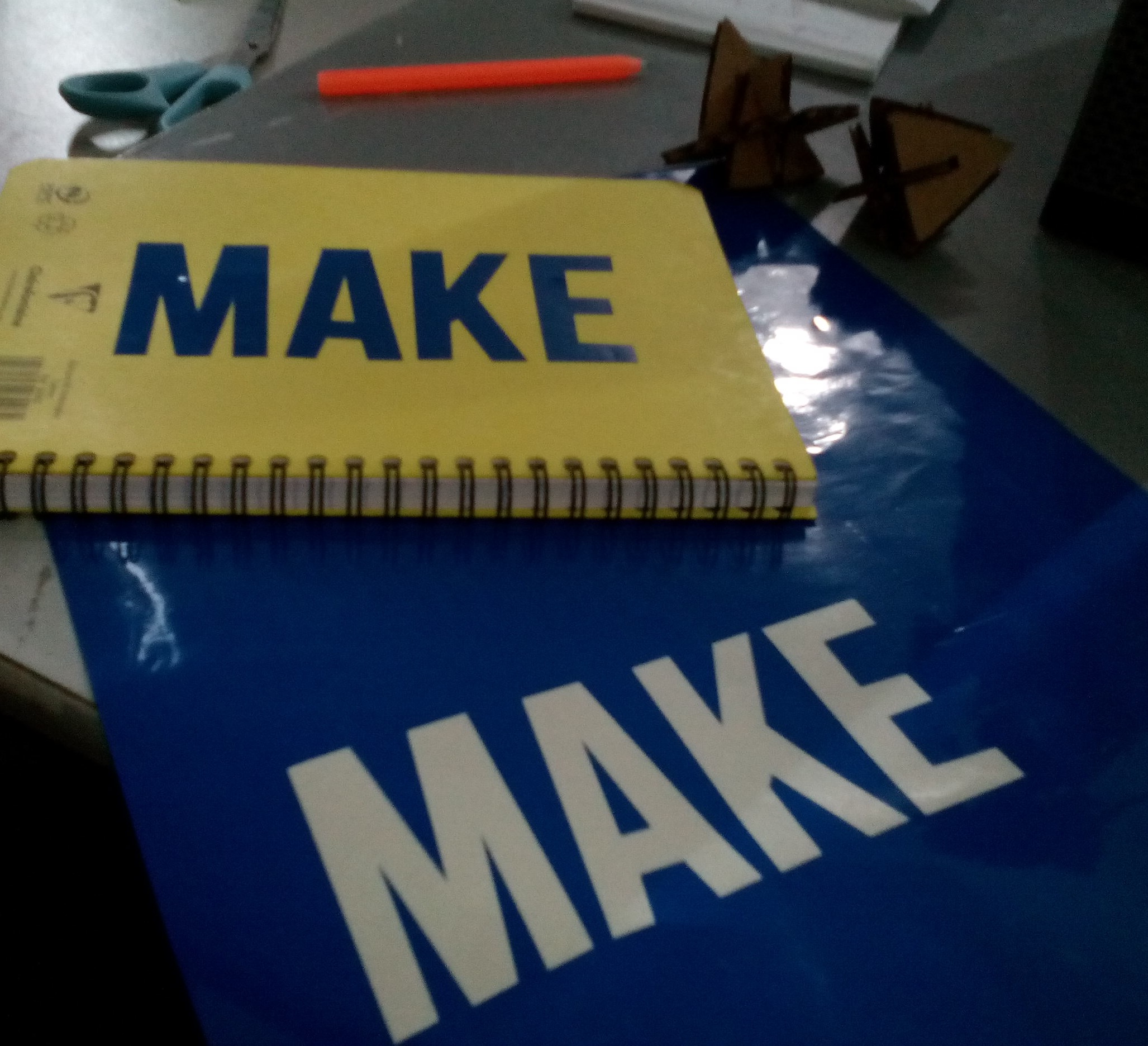
Please find the original .png file I used to vinyl cut my sticker --> Makespace Sticker
Go back HOME