Week 5 : 3D Scanning and printing
Assignment
-
Test the design rules for your printer(s) (group project)
-
Design and 3D print an object (small, few cm) that could not be made subtractively
-
3D scan an object (and optionally print it) (extra credit: make your own scanner)
3D printer
In our fab lab using Ultimaker2 3D printer.
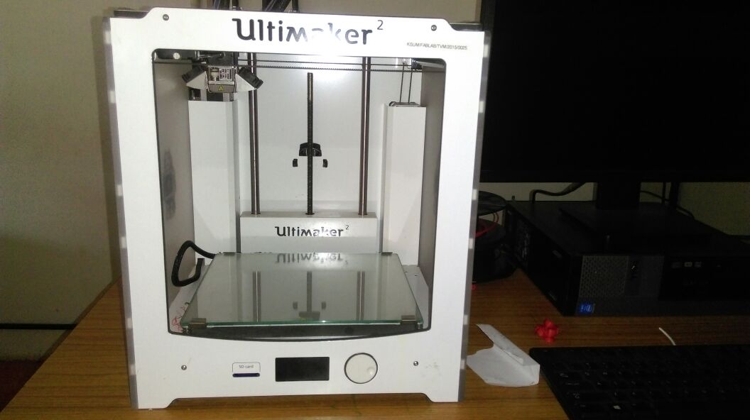
fetures of the ultimaker2
Build volume: 23 x 22.5 x 20.5 cm
Position precision X Y Z: 12.5 / 12.5 / 5 micron
Print speed: 30 mm/s – 300 mm/s
Travel speed: 30 mm/s – 350 mm/s
Nozzle diameter: 0.4 mm
Stand-alone SD-card printing
WiFi printing ready (future upgradeable)
Testing the 3D printer limitation
for the 3D printer testing and finding the limitation of 3Dprinter we looked on thinginverse and selected one.
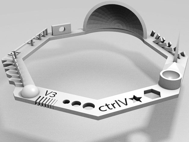
then we open the STL file in cura software, and it converts to gcode file because 3D printer is run in gcode base.
the printing process is complete
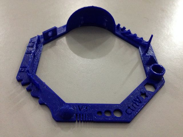
then we check 3D printer precision and inability in our guidelines are used.

-
Nut, Size M4 Nut should fit perfectly:yes got the perfect fit
-
Wave, rounded print:Looks fine
-
Star, Sharp Edges:yes
-
Name, Complex Shapes:Look fine
-
Holes, Size 3, 4, 5 mm:almost 2.8,3.74,4.7
-
Minimal Distance: 0.1, 0.2, 0.3, 0.4, 0.5, 0.6, 0.7 mm:0.5 mm was the minimum gap that was clearly visible, smaller than that wasn’t - this is probably because we were using the 0.4 mm nozzle size.
-
Wall Thickness: 0.1, 0.2, 0.3, 0.4, 0.5, 0.6, 0.7 mm Printed only 3 walls. This too would be because of the nozzle size.
-
Bridge Print: 2, 4, 8, 16 mm:Dimensions match
-
Sphere, Rounded Print 4.8mm height:around 4mm.
-
Overhang: 25, 30, 35, 40, 45, 50, 55, 60, 65, 70°:It was able to print all
3D Printing
3D printing or additive manufacturing is a process of making three-dimensional Solid objects from a digital file.Additive manufacturing process means it is created layer by layer. The different software is using for the 3D designing purpose like the blender, rhino, antimony,openscad, etc
In here I am decided open scad for the 3D modeling, for that firstly, I am download the openscad in my ubandu.for the openscad studying purpose I am referred some yotube videos.Moreover, we can easily learn openscad code using the openscad chatsheet used.
openscad design

Realy the open scad is used we can create design very easily. In here I am only used few cunning lines of code for my designing process
openscad codes
  $fn=50;
  difference()
  {
    cube(size = 4, center = true);
    sphere(r=2.5);
  }
  sphere (r=2);
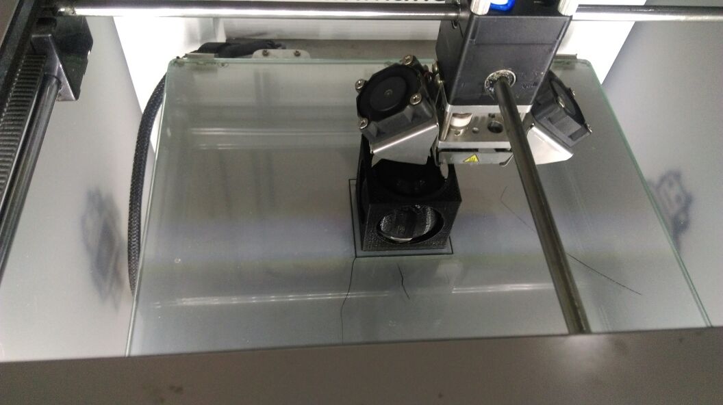
After the design process, I have opened this files in cura software.Cura software is the 3D model to toolpath slicing software.

then I change the setting of printing method

In here I am not to gave material support option because In my design inside of the cubed sphere is free in addition to that, removing of supporting material is difficult in my printed design
After setting process, i have converted the file into gcode.And gave the printing process
Final out
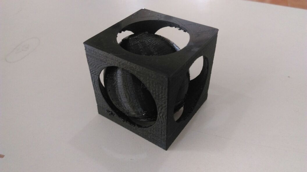
Orginal files
3D Scanning
3D scanning is a method of triangulation, this process is it determining the shape of object’s, and it converts digital form.To elaborate we have an object if we want to create a 3d digital form in that object then the different advanced 3D scanning equipment is used capturing the object, and it converts a Digital form.Nowadays different techniques are are using the 3d scanning process
What i did?
for the 3D scanning process I am choose the rolend modela and i fixed the R.A.P.S sensor instead of the millcutter. RAPS(Roland Active Piezo Sensor) technology is using this 3D scanning process.Main advantages of this technique are we can scan even glass or acrylic, but it is impossible with optical scanners because their light beams pass through the material.
RAPS Connecting with modela

Scanning object
then I stick my object with Roland Modela
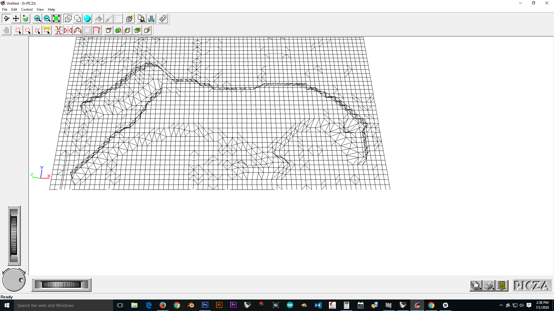
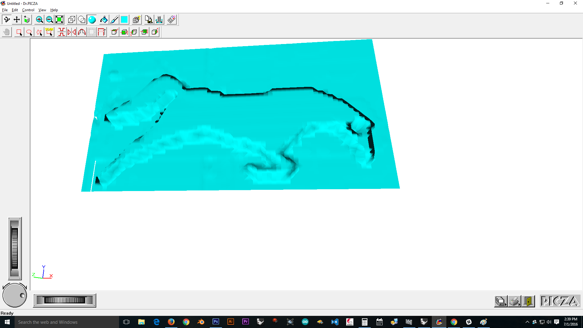
The Dr. Picza software which controls processing of 3d scanning for that I download the DR picaza.Then open the DR.picza, first we check the x-y position of our object in modela then we select the scanning area button in Dr.picza and to get the model x-y position of an object in picza moreover to set the z position, Z position gave the milling plate distance.
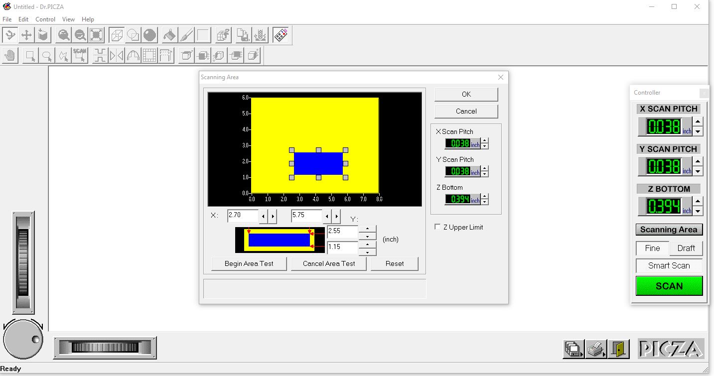
In our giving information checking purpose to click “Begin Area Test” and we note the movement of the pin is covering clearly or not.If it is ok then to click “scan” at a time it starts scanning process.
3D Scanning Result