I want to Program my ATtiny Board using Different Embedded Programing techniques.
Microcontrollers Overview
A microcontroller is a small computer (SoC) on a single integrated circuit containing a processor core, memory, and programmable input/output peripherals. Program memory in the form of Ferroelectric RAM, NOR flash or OTP ROM is also often included on chip, as well as a typically small amount of RAM. Microcontrollers are designed for embedded applications, in contrast to the microprocessors used in personal computers or other general purpose applications consisting of various discrete chips.
The Intel MCS-51 (commonly termed 8051) is an internally Harvard architecture, complex instruction set computing (CISC) instruction set, single chip microcontroller (µC) series developed by Intel in 1980 for use in embedded systems.
PIC microcontrollers are a family of specialized microcontroller chips produced by Microchip Technology . The acronym PIC stands for “peripheral interface controller.
The AVR is a modified Harvard architecture 8-bit RISC single-chip microcontroller, which was developed by Atmel in 1996.
ARM, originally Acorn RISC Machine, later Advanced RISC Machine, is a family of reduced instruction set computing (RISC) architectures for computer processors, configured for various environments. British company ARM Holdings develops the architecture and licenses it to other companies, who design their own products that implement one of those architectures—including systems-on-chips (SoC) that incorporate memory, interfaces, radios, etc. It also designs cores that implement this instruction set and licenses these designs to a number of companies that incorporate those core designs into their own products.
[MSP](http://www.ti.com/lsds/ti/microcontrollers_16-bit_32-bit/msp/overview.page Low Power Microcontrollers from Texas Instruments.
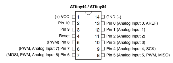
AVR - ATtiny 44 Microcontroller
- This is a Atmel 8 Bit low power micro controller combines 4KB ISP flash memory, 256-Byte EEPROM, 256B SRAM, 12 general purpose I/O lines, 32 general purpose working registers.
-
- ATtiny 44 have 31 General Purpose IO Registers
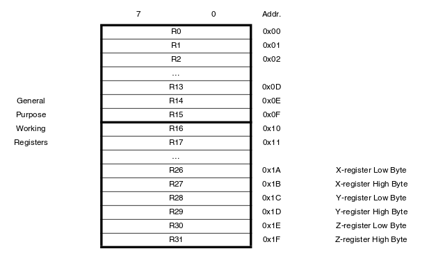
What is a register?
- Registers are special storages elements in microcontrollers with 8 bits capacity and they look like this:

Characters of Registers compared to other storage elements.
They are connected directly to the central processing unit called the accumulator.
They can be used directly in assembler commands,
Operations with their content require only a single command word,
They are source and target for calculations.
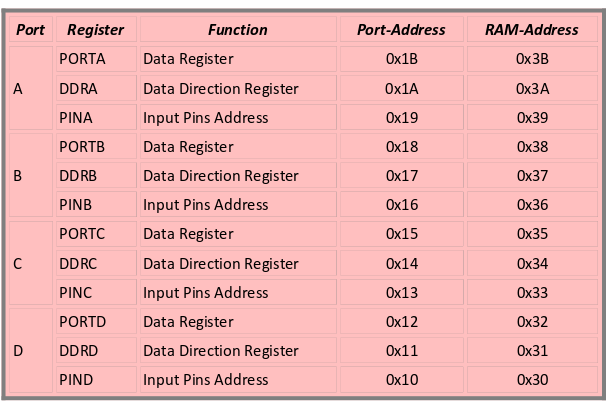
- List of Registers
-
How to Program ATtiny
We can program ATtiny in different methods now iam explaining how to program ATtiny using Arduino IDE and avr-gcc
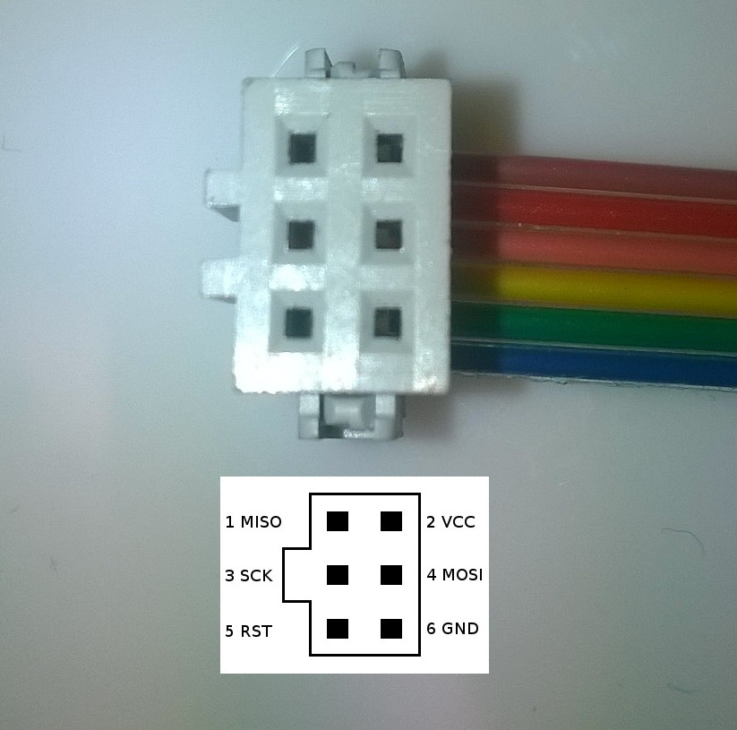
SCK(Serial Clock) :Programming clock, generated by the In-System Programmer (Master)
MOSI(Master Out – Slave In ) :Communication line from In-System Programmer (Master) to target AVR being programmed (Slave
MISO( Master In – Slave Out ) : Communication line from target AVR (Slave) to In- System Programmer (Master)
RST(Reset) : To enable In-System Programming, the target AVR Reset must be kept active. To simplify this, the In-System Programmer should control the target AVR Reset
GND(Ground) :Common Ground
VCC(voltage Constant Current) : VCC
ATtiny Programming Using Arduino IDE
You can easily program your AVR microcontroller using Arduino IDE for that you need the following items
- Arduino IDE
-
AVR ISP Programmer(FAB ISP/Arduino as ISP/ any other ISP Programmer).
I am using my FabISP programmer which i created in Electronics Production Week
- ISP Header Cables(6 Pin)
Start Programming
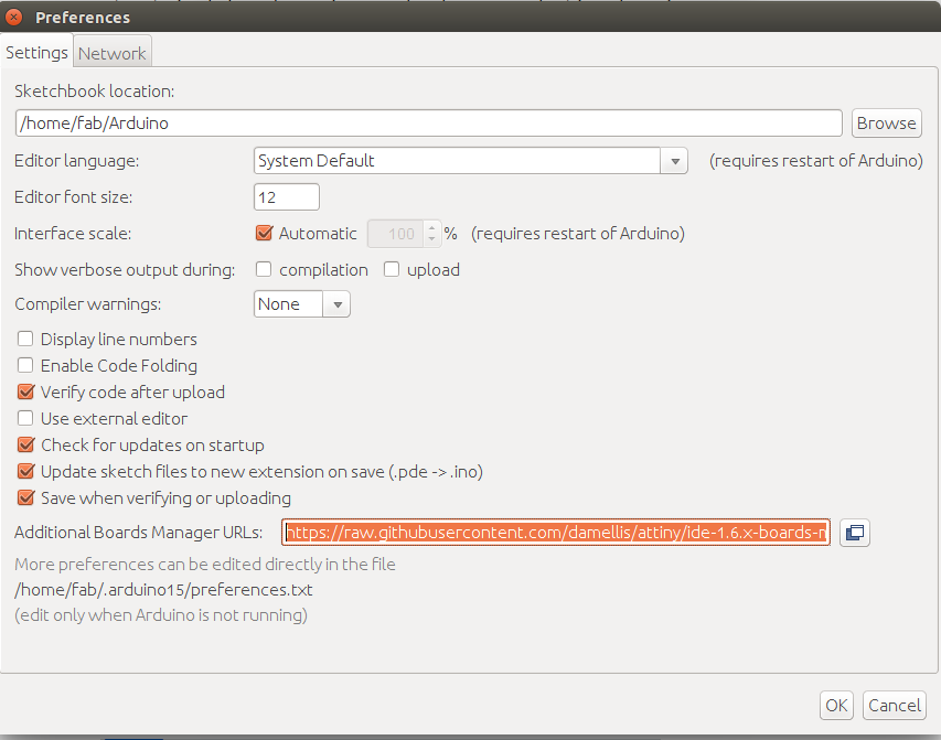
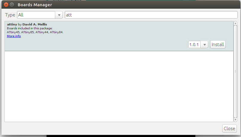
You need to install ATtiny library on Arduino IDE.
File >Preference add this code
https://raw.githubusercontent.com/damellis/attiny/ide-1.6.x-boards-manager/package_damellis_attiny_index.json
- :
Make the following changes in Board menu
Board -> ATtiny
Processor -> ATtiny44
Clock -> 20 MHZ(because i am using 20 MHZ Resonator in my Board)
Programmer -> USBTinyISP (because iam using Fab ISP)
- Then Connect FabISP with ATtiny Board.
-
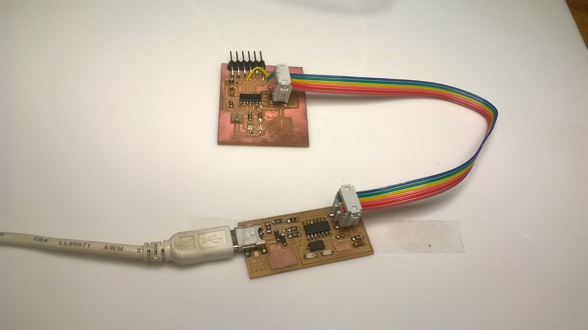
- 6 Pin ISP Male to Male Header Cable
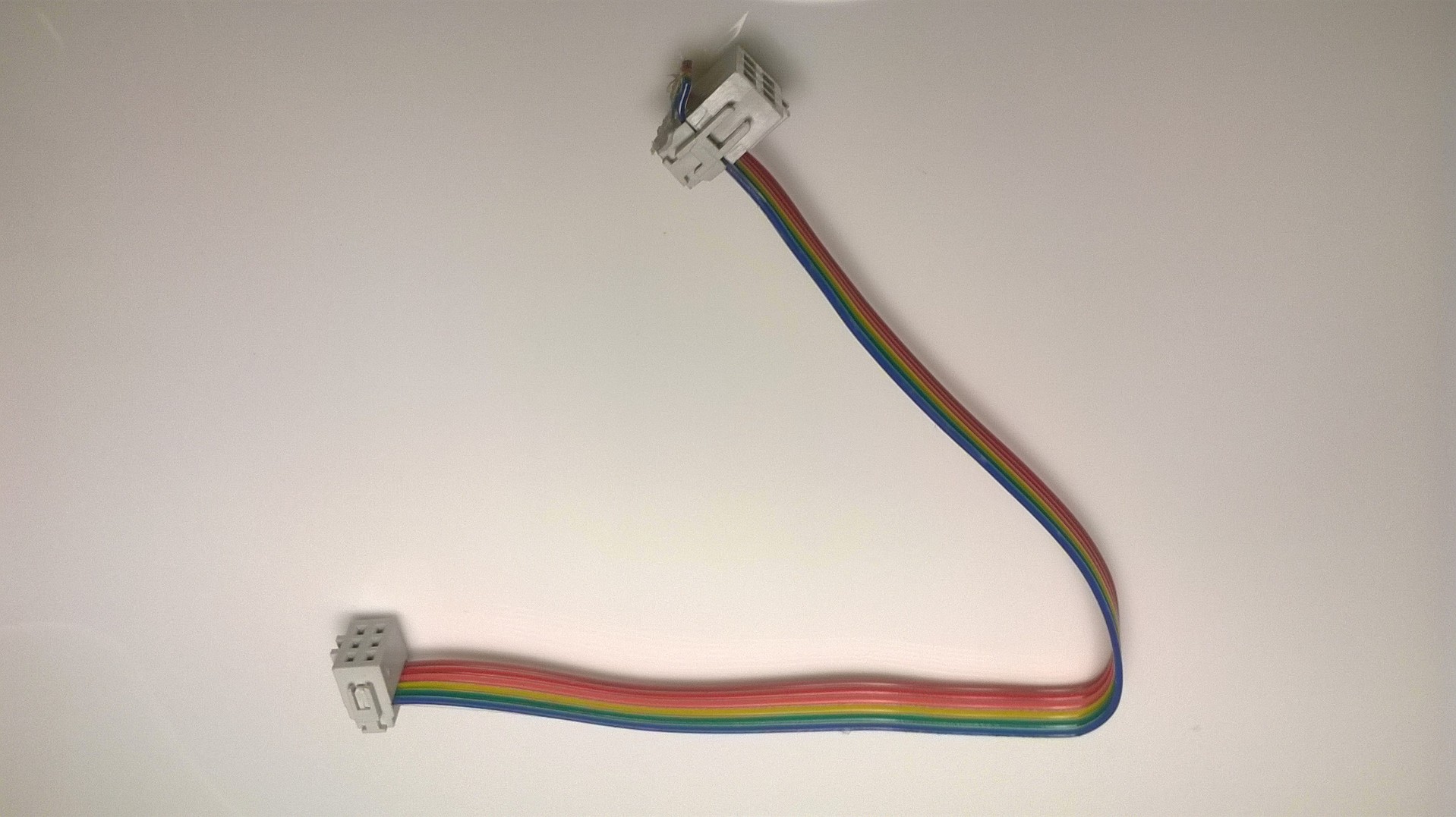
- ISP Pin Structure
After setting the above parameters i wrote program in Arduino IDE,i am familiar with arduino programming.
/*
Blinking Pattern With Push Buttun

By

Muhammed Jaseel P
FabAcademy 2016 Student
Fablab Trivandrum
*/


void setup() {

pinMode(7, OUTPUT);//Blue LED
pinMode(8, OUTPUT);//Red LED
pinMode(2,INPUT);//Push Buttun

}


void loop() {
if(digitalRead(2) == HIGH) //When Push Buttun Pressed
{
digitalWrite(7,HIGH);
delay(100);
digitalWrite(7,LOW);
delay(100);
digitalWrite(8,HIGH);
delay(100);
digitalWrite(8,LOW);
delay(100);

}
else
{
digitalWrite(7,LOW); //LED OFF
digitalWrite(8,LOW);//LED OFF
}
Final Outout
ATiny44 +LEDs+Switch from Jaseel on Vimeo.