
Electronics Design
The assignment for this week is to redraw the echo hello world board adding atleast an LED and a push button. For designing circuits, we have several tools like :
The CAD tool I have experience with is eagle ,which is nice to use and have auto route options.
First I am trying to design the echo helloworld board in 123D Circuits, which is an online tool (no need to install). It has options for simulation also.
The first step is go to 123D Circuits and sign up. For designing a PCB select "New PCB Design". Here we can draw the schematic of the circuit. There is a button "Add Component" at the right top to search and add the components.
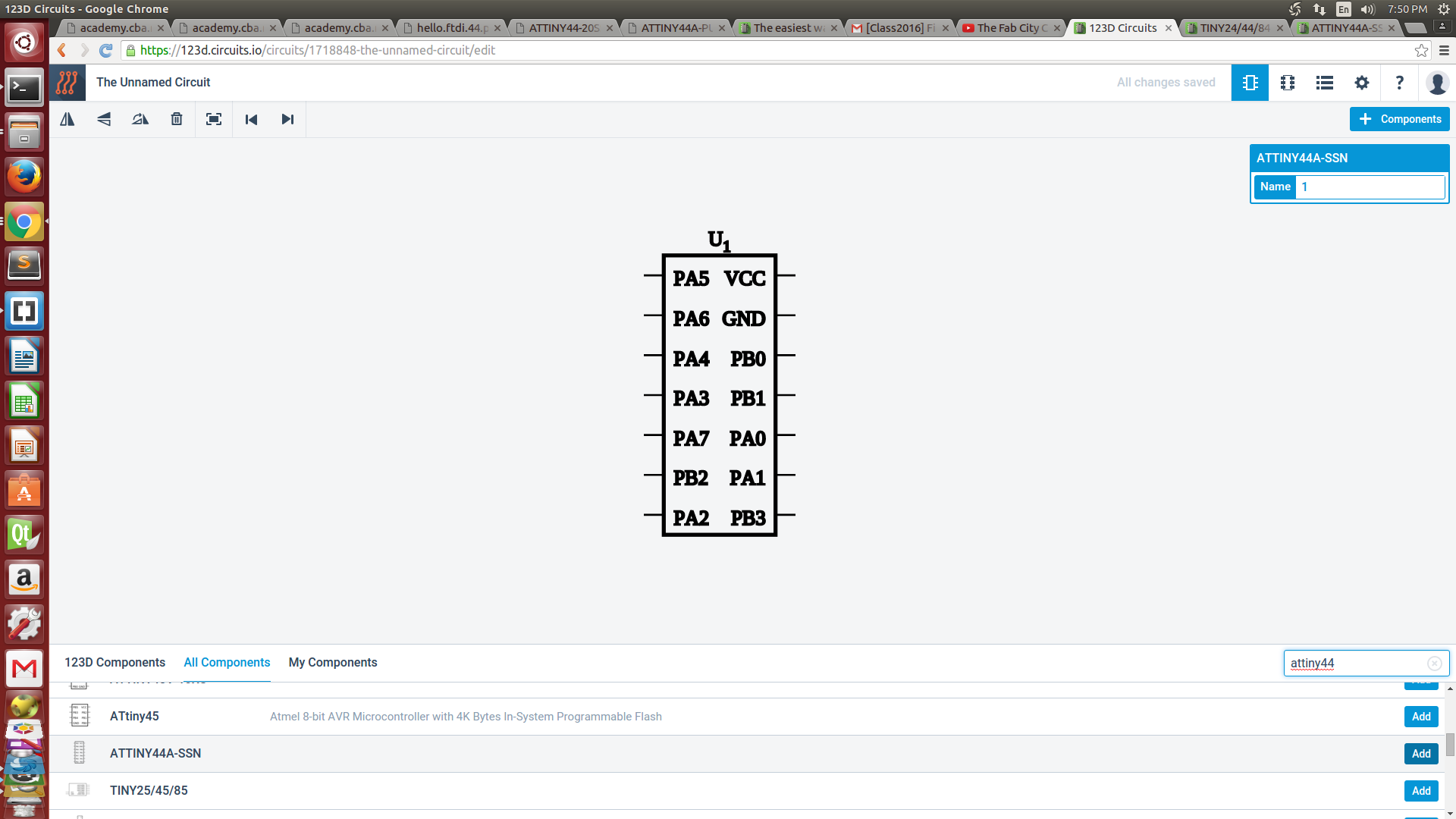
The components I added are
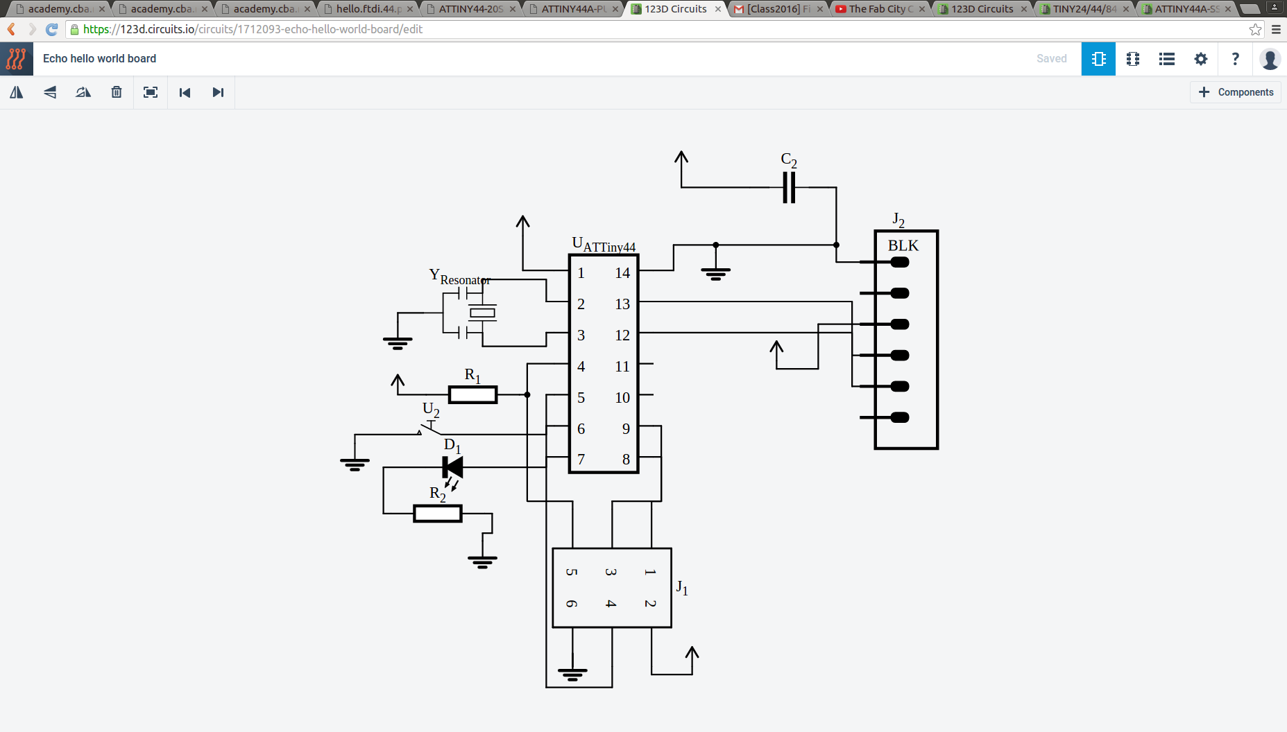
Once I added the components I connected them as per the design. I added an LED with a rsistance to the 6th PIN and a press button to the 5th PIN of the ATtiny44.
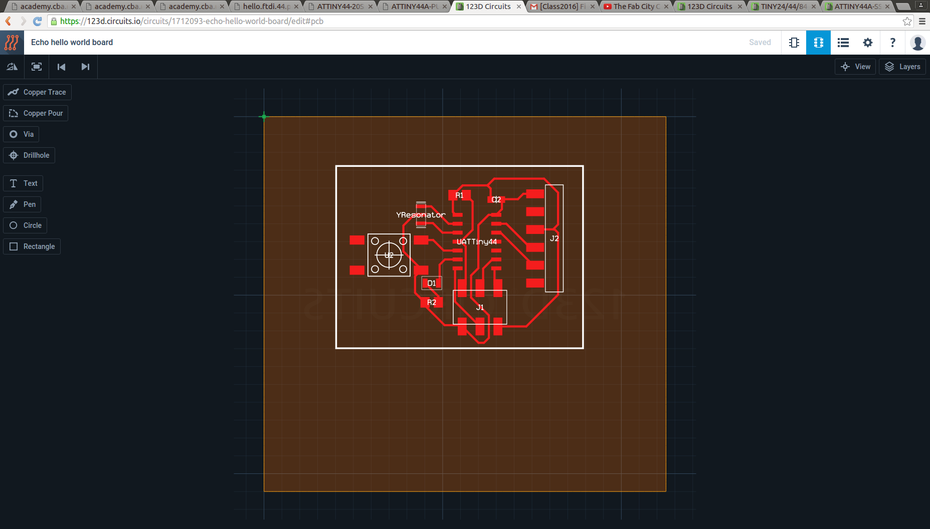
If we complete the drawings we can move to the pcb view. There is a button at the top right for moving to pcb view. Here we have to arrange the components according to our need. The components will be connected with green lines. For drawing the coper trace we have to cick on "Copper trace" which is at the top left. Here is the major problem i found with this tool, there is NO AUTO-ROUTE !! We have to draw manually with the help of some tools.
See the board i drew :
We can download it as gerber file. Here is it.
The merits of this tool I felt is
The main demerits are
Here I just added an LED and a button, and it is very dificult draw the coper traces manually if there are more components. Next I am designing a ciruit in Eagle so that we can compare these tools.
Designing in Eagle
EAGLE (Easily Applicable Graphical Layout Editor ) is not a online tool like 123D Circuits . It is available for Windows, Mac and Linux and you can download it for free.
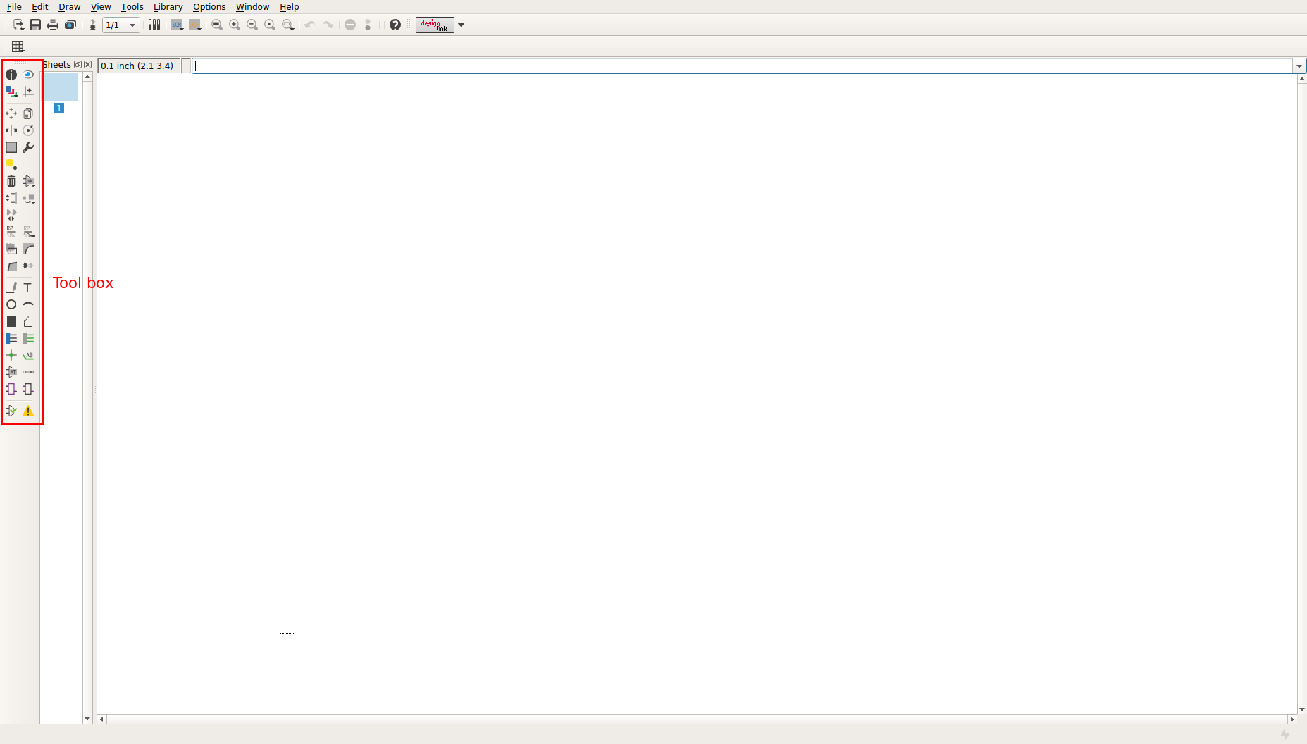
ONce you install eagle ,open it and start a new project. Under that project start a new schematic. (File --> New --> Schematic).
This is the place where we draw the schematic diagrams. There is tool box on the left side where all the tools are available.
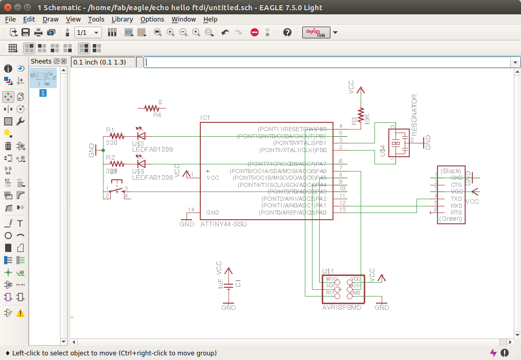
Here is the schematic diagrom of the hello ftdi board. I have added two LEDs and a switch.
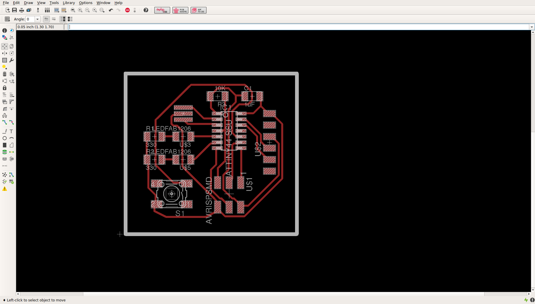
Next step is to arrange the components on the board. For that there is an option "Switch to board". Click on that. Here we have to arrange the components as wee need to be in the PCB. After arranging, click on the Auto route option to route it.
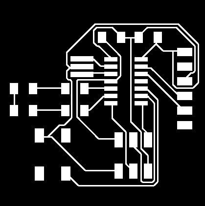
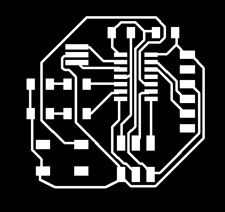
I forgot to take the scree shot od that. But i have the exprted monochrom png image I used to mill. See it here:
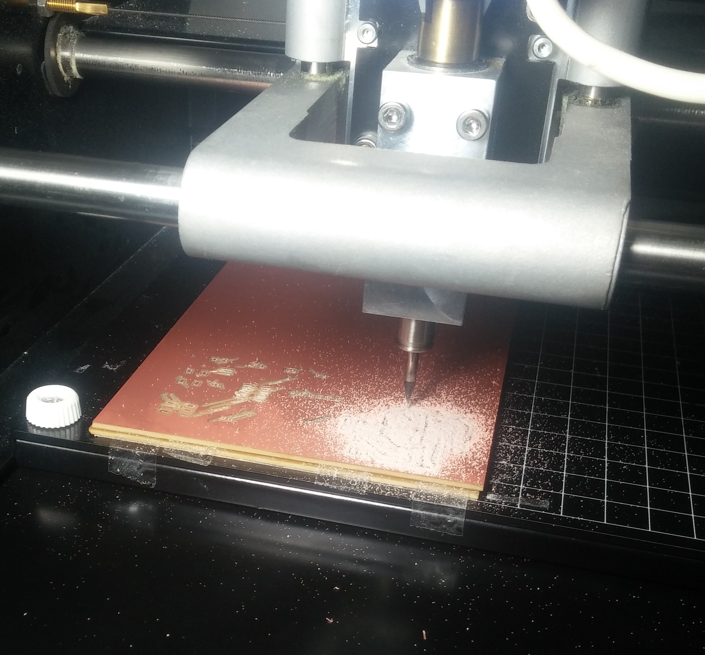
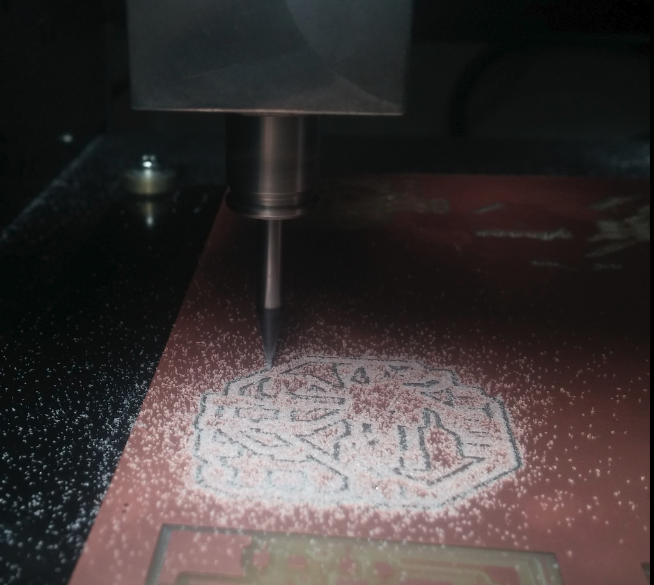
I milled the PCB with that file using our Modella PCB miller.
But see what happened. Some traces are missing, the coper traces comes out.
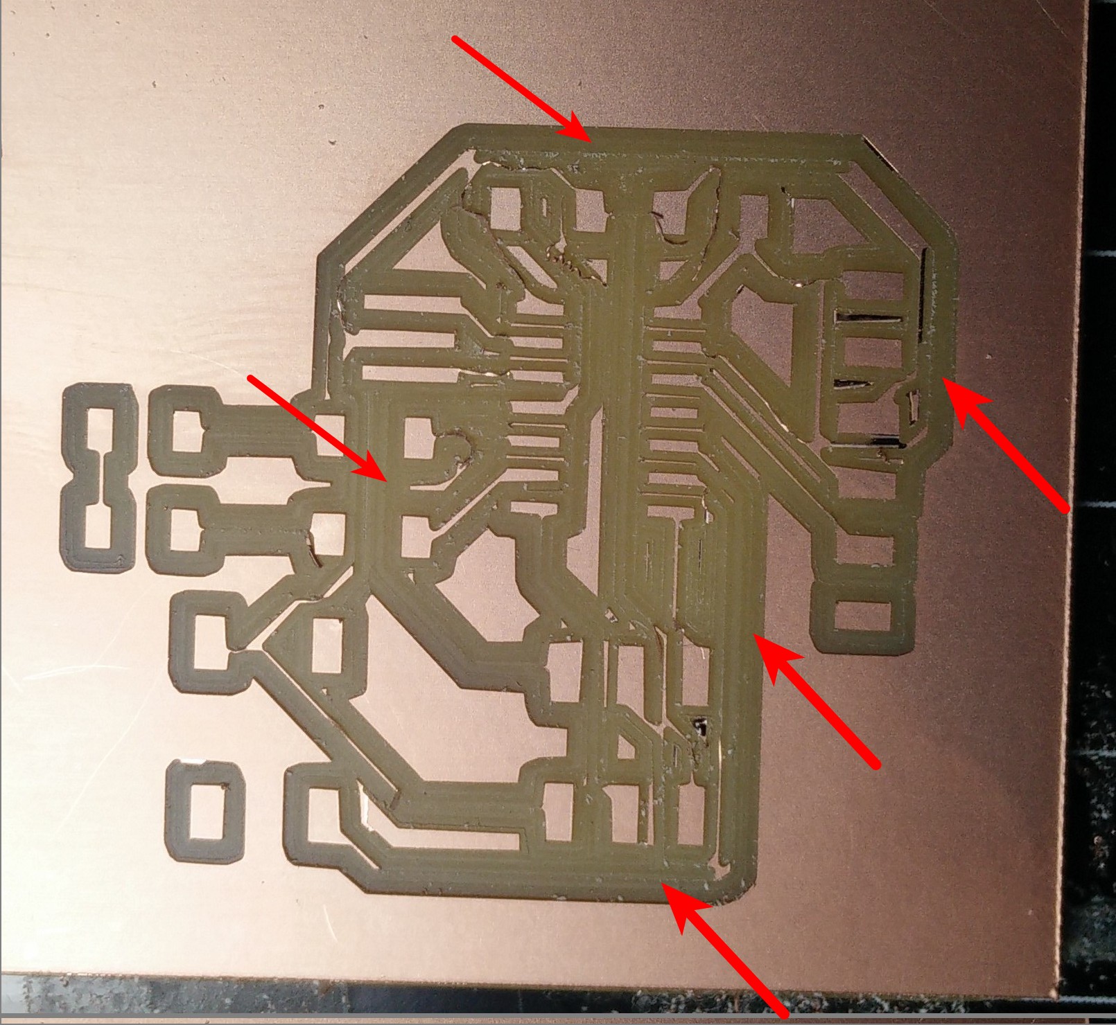
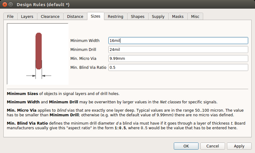
The reason was the Trace width. I gave the trace width as 12 mil and the clearance as 15 mil . The better and recommended is 16 mil, but i tried 12 mil to know what happens and i realized what happened :P
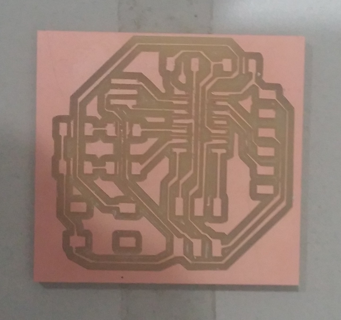
I changed the trace width to 16 mill.
I tried the auto route once more with the same diagram.
I milled it.
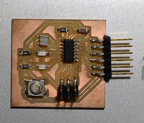
I soldered the components
Here is the original files i used to mill. mill file cut file