
Assignment- To implement a network using microcontrollers demonstrating the concepts in networking such as, identity, parallel programming ability and protocols.
To get familiar with the concepts of networking I used Neil’s serial Communication examples, and redesignned them to carry a button and an LED.
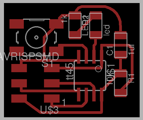
This uses attity 45 chip. I use the pins connected to isp as the trasmitter(tx) and receiver(rx) pins too, so that I can use the ISP pins for communications between the boards. SCK and MISo are used as as tx and rx. I wanted to add resonator but couldnt.
There are two board here, the bridge and the node. The bridge connects the computer to the network of microcontrollers through ftdi cable. The node is connected to the bridge through ISP cable. It shares many pins but tx and rx are important. I created one of each.
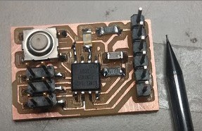
Since we ran out of smd header pins for FTDi interface at the lab, I have added holes in the smd header pads so that I can solder throughhole pins instead.
Features
- Uses ISP pins also for communication. Downside is that some pins are shared.
- Has LED for output, switch for input.
- Has through hole as well as smd mounting for ftdi access.
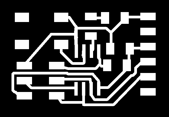
Bridge Layout.
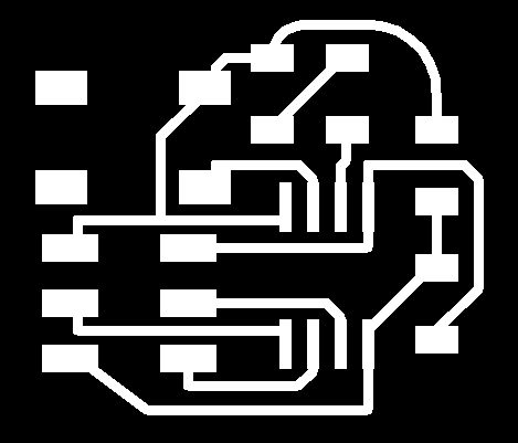
Node Layout.
Eagle files for download
Bridge Schematic
Board
Traces
Cutout
Node Schematic
Board
Traces
Cutout
No problem with milling.
Bridge
In Neil’s code I made the following changes.
Change LED pin.
#define led_pin (1 << PB3) //**Changed tx and rx.
#define serial_pin_in (1 << PB2) //to tx
#define serial_pin_out (1 << PB1) //to rx
I uploaded the program with node id hardcoded to identify wach board.
For bridge
#define node_id '0'For node
#define node_id '1'On sending a either 0 or 1 from the serial FTDI the bridge or the node react to it and output message identifying themselves by their node id.
Download code for bridge
Download code for node
Download makefile
Here we are giving an identity to each node hardcoding a line of code that identifies them. When something interacts in the serial lines it could be any random thing, each and every node listens to it and if it finds that the message is addressed to it, like by calling its name them it responds by by running the routine that is meant to run when it is called.
From the computer we are sending a message in the serial communication channel. This message is the name of the node, both the nodes listen to it but the once whose name is the called responds by blinking differently and sending response string.
I tried to make one of the boards as the master and the other as slave. This requires no computer but only communication between each board. The rx and tx pins are reversed in the master and the slave.
// in master

#define serial_pin_in (1 << PB1) //**
#define serial_pin_out (1 << PB2) //**

//in Slave
#define serial_pin_in (1 << PB2) //**
#define serial_pin_out (1 << PB1) //**
The master has node id ‘0’ when the button is pressed in the master, it sends the character ‘1’ to the slave and the slave supposed to respond by flashing the LED.
I couldnt get this to work though. The reason could be timing accuracy or the button bounce.
Download master C code
Download master makefile
Download slave C code
Download slave makefile