
Table Of Content
This was the logo for the old final project concept
![]()
I decided to challange myselfe with something that could be useful in my dayliy life. Having a couple of 4-years-old twins I thought about something that could help me in the goodnight storytelling since every night my kids ask me for some new story to be invented fot them. If you want to invent a story at the beginning it is funny to diverge and just start randomly to tell something but soon you realize that you cannot go too much further this way. You have to follow some basic plot scheme.
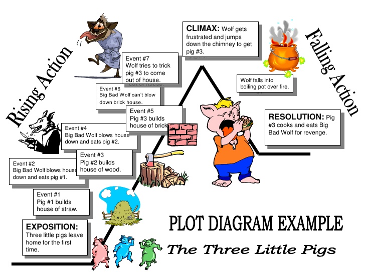
Some help comes from the basic plot diagram of most child stories:
First main characters are introduced, then something happen that break the initial equilibrium until the story reach the climax and then the closure.
My idea for the final project is to develop a device that can help me to follow this path while improvisating a story. Moreover this device should suggest characters, scenarios and actions.
On week 2 I used procreate to sketch the concept design of my project:

This App has also an interesting feature which allows you to share a video with the timelapse of your work, se mine here:
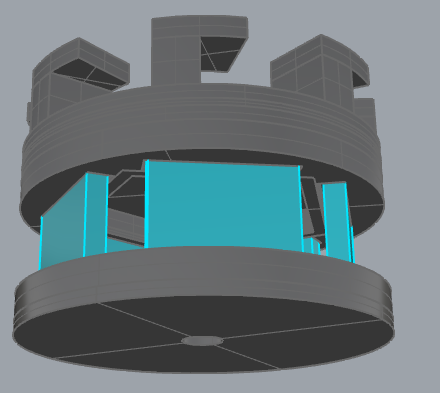
With Onshape (look for “Once_upon_a_time” public project) I designed also a 3D model:
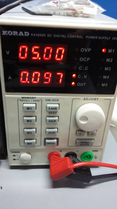
I decide to use a common 60 mm desktop PC fan as motor for my spinning mirrors assembly. It is very quiet, goes very cheap and it can be easily found for free.
At 5V it have a current consumption of about 0.1 A:
The most interesting part of this motor for my project is that it have a tachimetric signal provided by the yellow cable. A resistor between 5V and the yellow cable is needed since the signal is up for half of the cycle, then is pulled to GND for the other half. I found some good hint on how PC fans works here

I measured the signal with a DS1254 Rigol wavefor analyzer:
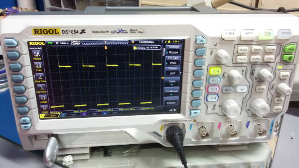
The signal is very clear, 80Hz speed at 5V:

The rising edge of the signal is very steep, no debounce will be needed.

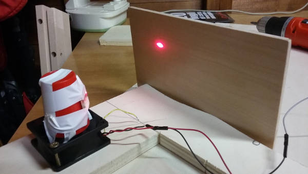
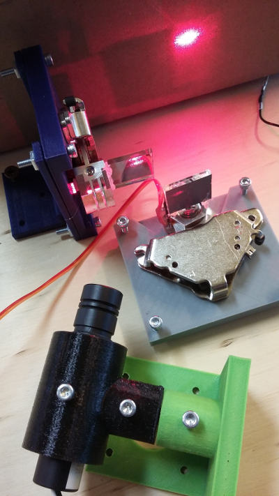
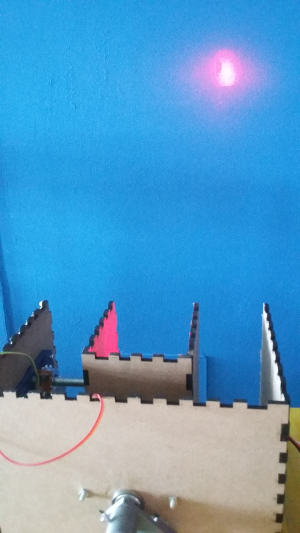
Then I tried the effect of the laser on a spinning 20x20mm mirror attached to the fan.
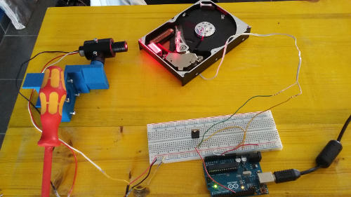
This was my test bed:
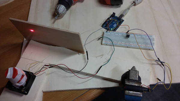
I used Arduino to make one 1 ms laser cycle:
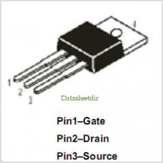
To do that I used a IRF520N mosfet and a simple sketch that switched on the laser beam for just 1 ms asynchronously respect the fan rotation (this is why the line segment “moves”)
I used a simple laser pointer as a first cheap and safe solution, but it get broken soon, so I had to move to a new TTL 0.2 W laser (16mm diameter) which I found in the FabLab.

This was my first attempt to read the tachimetric signal (use that 0-5V signal instead the button). The LED flashes with a 10 ms period because of the debounce delay of the button:
Wood enclosure of the laser projector


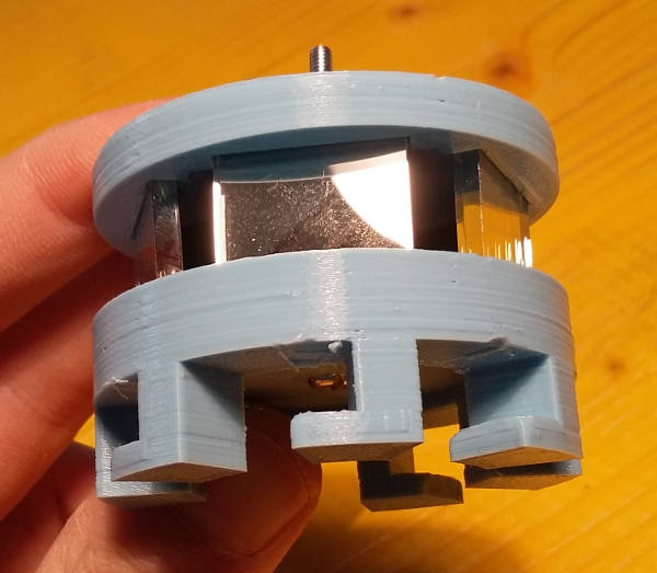
Plastic support of mirrors

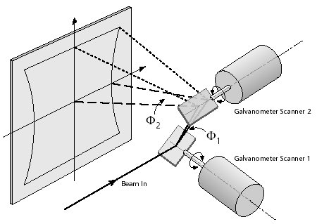
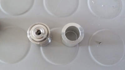
I tried also another approach using HD voice coil heads:
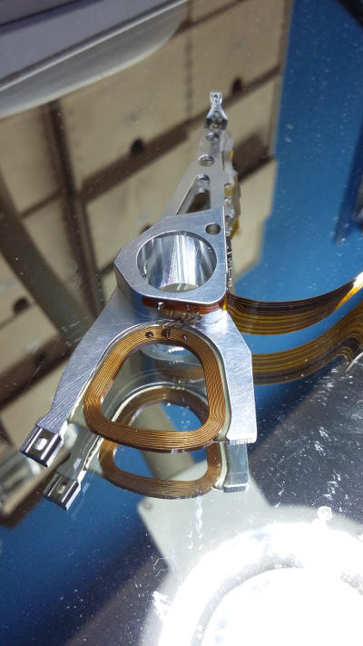
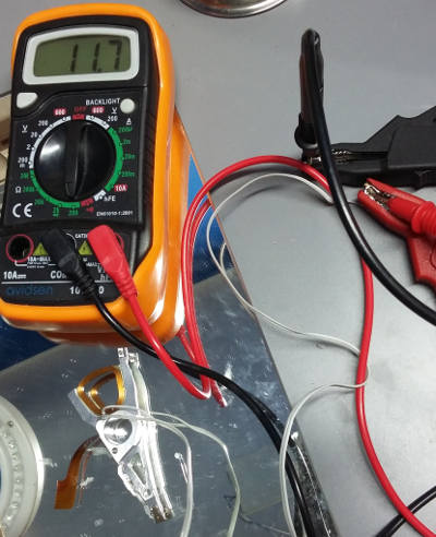
Those can be powered with direct voltage
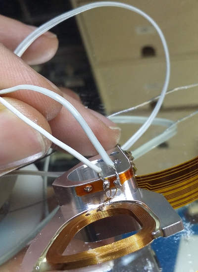
I made some tests in order to see if the HD voice coil could move the mirror fast enough to drow lines with the laser dot
Changing voltage changes the position of the head which has been fixed from one side with an elastic
And controlling it with Arduino IDE…
Mirror support

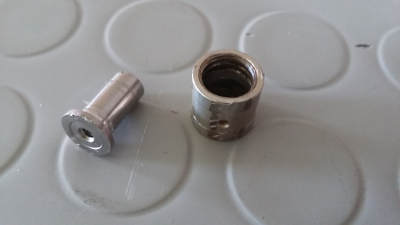
Custom bearing
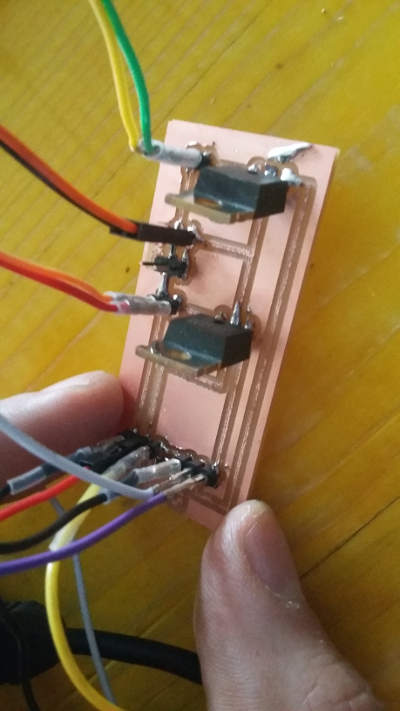
Mosfet driver board
This is the script derived from the classic “FADE” example that should draw a circle:
int ledx = 9;
int ledy = 10;
int brightnessx = 0;
int brightnessy = 127;
int fadeAmount = 5;


void setup()  {
  // declare pin 9 to be an output:
  pinMode(ledx, OUTPUT);
  pinMode(ledy, OUTPUT);
}


void loop()  {
  // set the brightness of pin 9:
  analogWrite(ledx, brightnessx);
  analogWrite(ledy, brightnessy);

  brightnessx = brightnessx + fadeAmount;
  brightnessy = brightnessy + fadeAmount;

  if (brightnessx == 0 || brightnessx == 255) {
    fadeAmount = -fadeAmount ;
  }
  if (brightnessy == 0 || brightnessy == 255) {
    fadeAmount = -fadeAmount ;
  }

  delay(1);
}
HP Printer rotary encoder