
Table Of Content
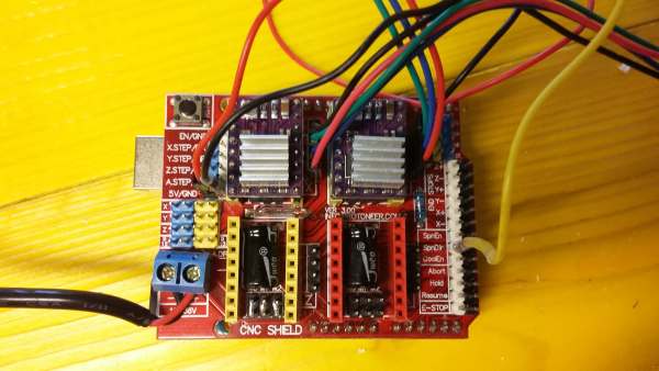
CNC shield is a GRBL compatible shield for Arduino (and then with our Satchakit). We will use just 2 axis and spindle enable to switch on and off laser.
Concept : A machine to draw on a wall with a laser
The laser pointer should be able to plot inputs from different sources, both real time and offline:
We decided to use a linear approximation between angle and linear distance on the wall where the laser will draw lines. This approximation is acceptable for small angles (sin(ϵ)≅ϵ), following picture represent the error between angle and tangent for growing angles:
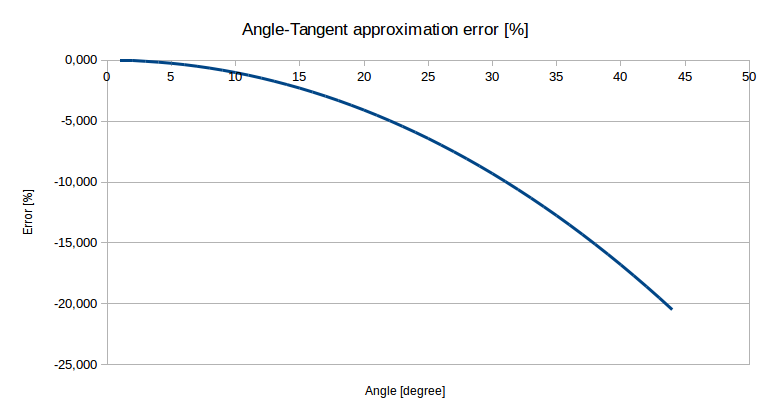
We chose as rule of thumb a maximum error of 10% (at the borders of the screen). This means that from the center the pointer should not move more than 30°:

Given this limit on the angular movement, we have a maximum “screen” width for different distances equals to the distance itself times Tan(30) = 0.577. From this we can calculate our step size which will be of 69 mm per step for a wall at 2 meters from the laser pointer or 2.2 mm per microstep for a 32 microstepping driver.
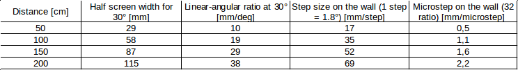
In GRBL we’ll set the number of steps for 1 mm (G code is in terms of mm) according to the wall distance (2.2 mm/microstep according to our calculation).
CNC shield and stepstick assembled with all wiring (laser connected to PinDir):
We started from some models found on thingiverse to hold Nema 17 stepper. We modified a little one part with blender (works nicely with meshes).
Unlikely after a long print, the part get broken, maybe due to poor filling.
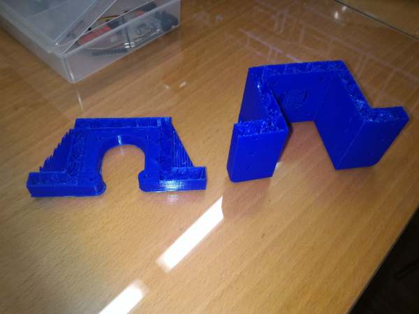
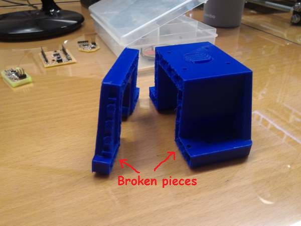
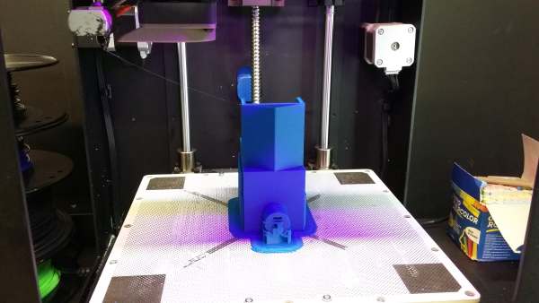
We then decided to move to a lighter and faster structure and to use wood laser cutted support for the base and for the vertical motor (X axis) holder.
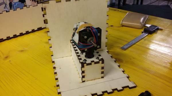
We had only a small piece of plywood available, so we designed a box that works as base, protection and motor holder using as much as possible the available material:

The case was designed with MakerCase and modified a little with Rhino to insert the motor holder

From the behind of the case there is a hole to manage stepper cables


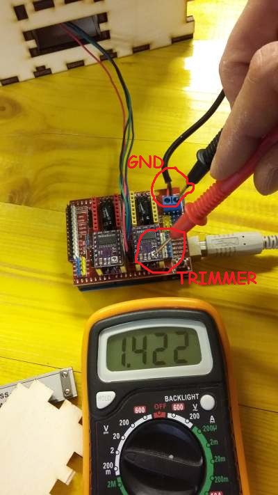
On the drivers website we found some tips about calibration. A rule of thumb is to set the Voltage between the trimmer and ground at something between 1 and 2 Volts. This number has to be adjusted according to moto behaviour
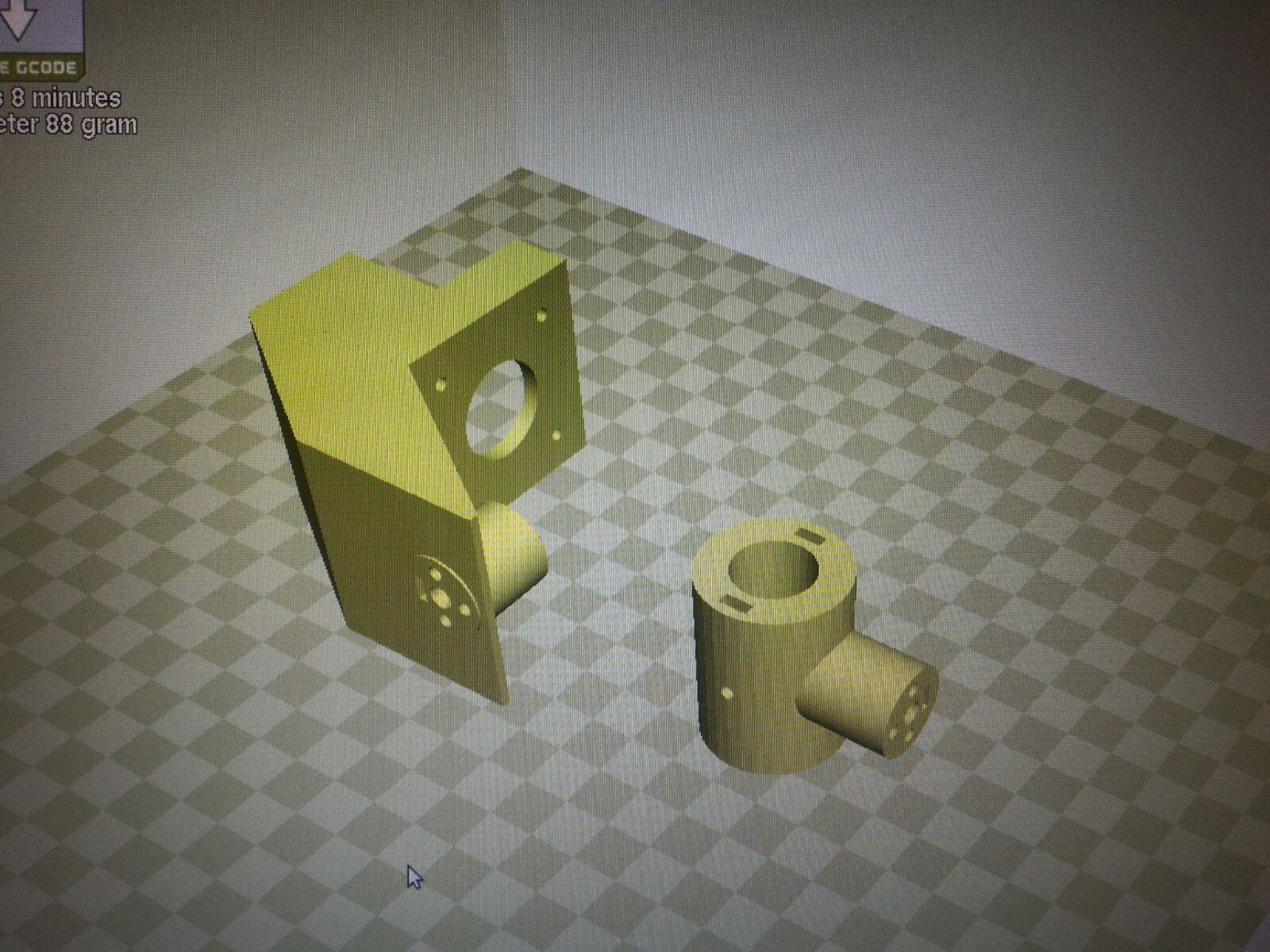
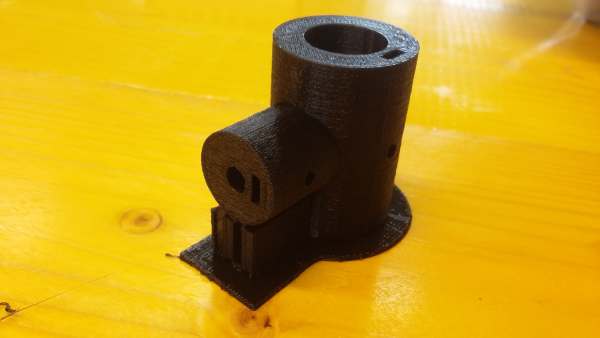
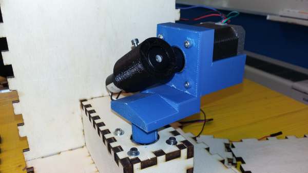
For the upper, horizontal stepper motor (Y axis) we designed and printed a custom part. We ran a printing at 150% speed increasing the temperature from210 to 220 °C (PLA). The print went pretty well except some material filaments on extruder travel
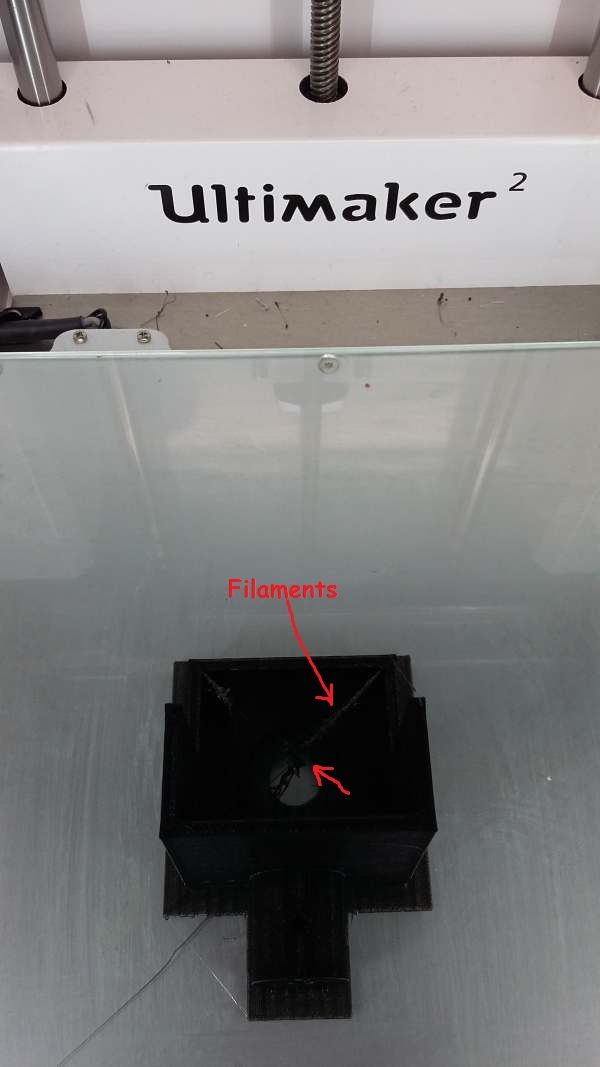
After a first try where the motor wasn’t actually fitting well in the older due to material retraction, we redesigned the part increasing a little bit the space (0.1 mm of tolerance).

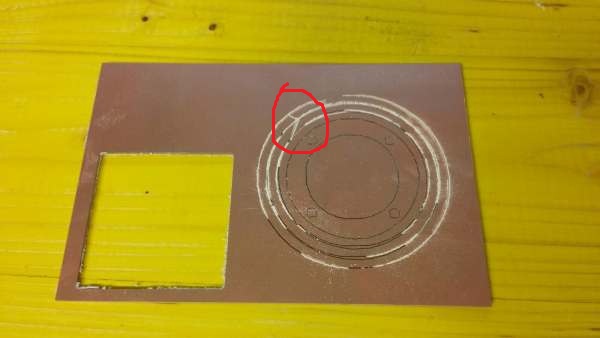
We designed a PCB with concentric paths to transfer connection from below to the apper, rotating, part.
We got many problems doing this.
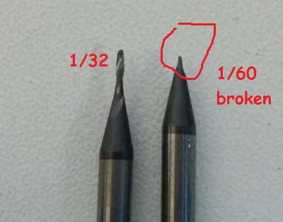
First the tool of the milling machine got broken:
Then the PCB which we were milling moved from its support right in the middle of the job (see the cut did by the tool of the milling machine)
Moreover, when we succeeded to mill traces, we still got a bad result because the PNG were not saved with an edequate resolution.
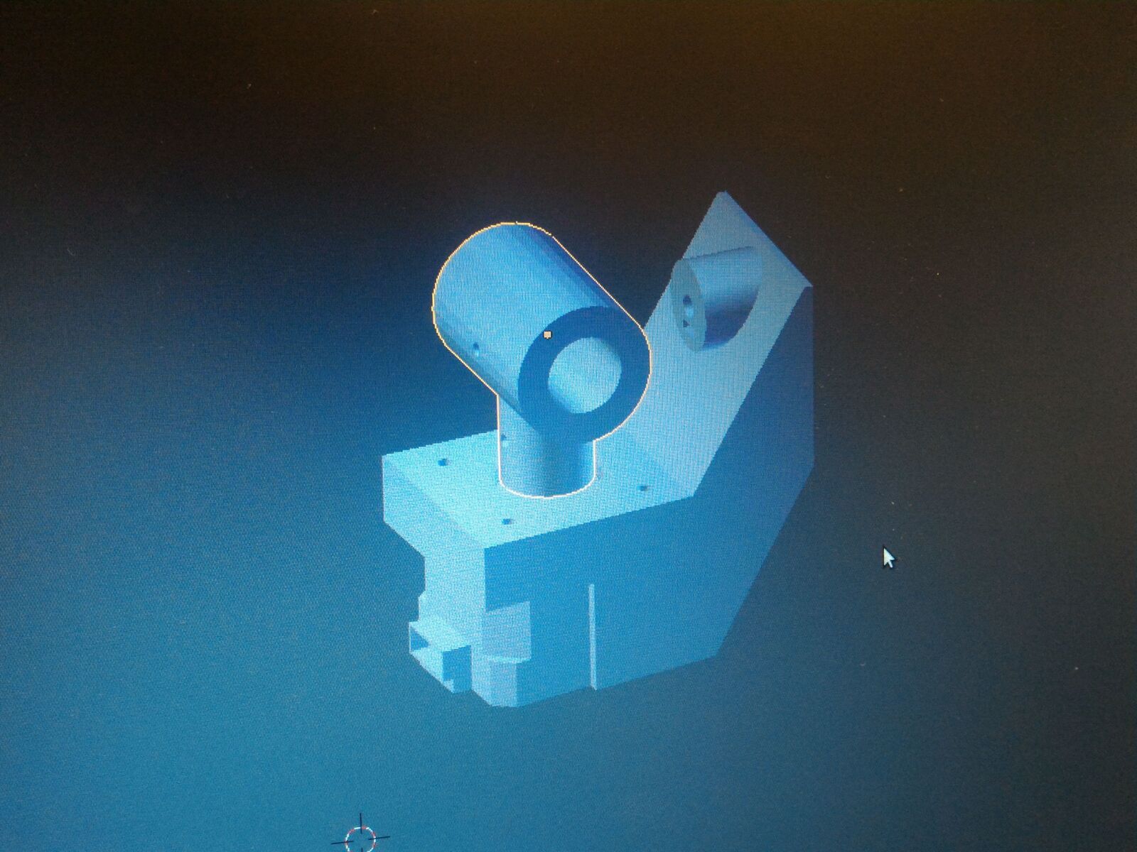
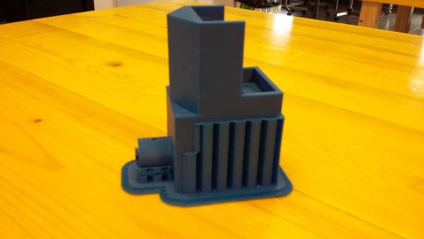
We realized that the support for the upper motor made the laser not in the center of rotation. This would lead to a not precise control of the drawned point, so we redesigned the part this way:

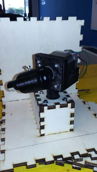

And in the end we tried to move the motor to see how it was working.
Open Source Hardware
OffiCucina
PDF model
Make: enciclopedia of electronic components
Practical electronic for inventors
Making Things Move DIY Mechanisms for Inventors, Hobbyists, and Artists - Dustyn Roberts