Table Of Content
The
ATtiny44 datasheet
includes all the features and all information about registers of the MCU.
Main characteristics are:
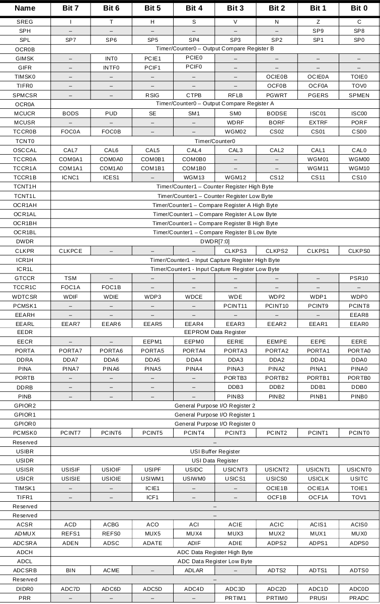
ATtiny registers:
ATtiny pinout:

In order to go from the concept of a program to a running board one have to accomplish different steps using specific tools, that is a toolchain:
[preamble & includes]
[possibly some function definitions]
int main(void){
[chip initializations]
[event loop]
while(1) {
[do this stuff forever]
}
return(0);
}
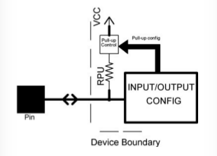
AVR devices have multiple I/O ports named PORTA, PORTB, PORTC, etc. Each I/O port can have a maximum of eight pins. Each port has three registers associated with it:
- DDRx: Data direction register (0= input, 1= output) These registers control whether each pin is configured for input or output the data direction. After a reset or power-up, the default state is all zeros, corresponding to the pins being configured for input.
- PORTx: Data output register (0= hi-Z, 1= VCC/pull-up) controls whether that pin is set to logic high or low, with the DDR configured for input, setting the PORT bits on a pin will control whether it has an internal pull-up resistor attached or whether it’s in a “hi-Z” (high-impedance)
- PINx: Data input register (read the logic state) digital voltage values for each pin that’s configured as input
DDRB ⫽ 255; //In decimal
DDRB ⫽ 0xff; //In hexadecimal notation
DDRB ⫽ 0b11111111; //In binary notation
Function definition:
int GetMax(int a, int b);
Function call:
int GetMax(int a, int b)
{
if(a > b)
return a;
else
return b;
}
`#include "filename"
The _BV() macro is just a bit-shift tool, Macro can be also used to name fixed numbers like PI.
`#define _BV(bit) (1 << (bit))
`#define PI 3.1415
void main ( )
{
float circle_area, circle_circumference;
int radius = 5;
circle_area = PI * radius * radius;
circle_circumference = 2 * PI * radius;
}
It is possible to explicitly compile all source files together like this:
gcc main.c another_file.c serialLibrary.c -o main
Which makes an executable file, main, from all of the listed .c files. Or, you can write a makefile that maps out these dependencies:
main: main.c another_file.c serialLibrary.c
Names on the left side of the “:” are targets, and on the right, their dependencies.
Lines beginning with # are treated as comments in the MAKEFILE.
Makefile definitions:
Makefile example:
`# MCU name
MCU = attiny861 (This tells the compiler that the microcontroller for which the application has to be compiled is Attiny861.)
`#Output format. (Can be srec, ihex, binary)
FORMAT = ihex (The final output file has to be in hex format.)
`# Target file name (Without extension)
TARGET = main (This is the name of your hex file.)
`# List C source files here. (C dependencies are automatically generated.)
SRC = $(TARGET).c (This line shows the name of the source file. The command $(TARGET) is replaced by the value of TARGET that is main. Hence, you have to keep the name of your source file as main.c.)
`# If there is more than one source file, append them above, or modify and uncomment the following:
`#SRC += abc.c
SRC += def.c
The hello world makefile:
PROJECT=led_button
SOURCES=$(PROJECT).c
MMCU=attiny44
F_CPU = 8000000

CFLAGS=-mmcu=$(MMCU) -Wall -Os -DF_CPU=$(F_CPU)

$(PROJECT).hex: $(PROJECT).out
    avr-objcopy -O ihex $(PROJECT).out $(PROJECT).c.hex;\
    avr-size --mcu=$(MMCU) --format=avr $(PROJECT).out

$(PROJECT).out: $(SOURCES)
    avr-gcc $(CFLAGS) -I./ -o $(PROJECT).out $(SOURCES)

program-bsd: $(PROJECT).hex
    avrdude -p t44 -c bsd -U flash:w:$(PROJECT).c.hex

program-dasa: $(PROJECT).hex
    avrdude -p t44 -P /dev/ttyUSB0 -c dasa -U flash:w:$(PROJECT).c.hex

program-avrisp2: $(PROJECT).hex
    avrdude -p t44 -P usb -c avrisp2 -U flash:w:$(PROJECT).c.hex

program-avrisp2-fuses: $(PROJECT).hex
    avrdude -p t44 -P usb -c avrisp2 -U lfuse:w:0x5E:m

program-usbtiny: $(PROJECT).hex
    avrdude -p t44 -P usb -c usbtiny -U flash:w:$(PROJECT).c.hex

program-usbtiny-fuses: $(PROJECT).hex
    avrdude -p t44 -P usb -c usbtiny -U lfuse:w:0x5E:m

program-dragon: $(PROJECT).hex
    avrdude -p t44 -P usb -c dragon_isp -U flash:w:$(PROJECT).c.hex
Open a terminal in a folder where you have the makefile and all its sources:
diego@diegoHP:~/led_button$ sudo make -f led_button.make

avr-gcc -mmcu=attiny44 -Wall -Os -DF_CPU=8000000 -I./ -o led_button.out led_button.c
avr-objcopy -O ihex led_button.out led_button.c.hex;\
avr-size --mcu=attiny44 --format=avr led_button.out
AVR Memory Usage
----------------
Device: attiny44

Program:     106 bytes (2.6% Full)
(.text + .data + .bootloader)

Data:          0 bytes (0.0% Full)
(.data + .bss + .noinit)
This page from
Ladyada
explains very well how avrdude works.
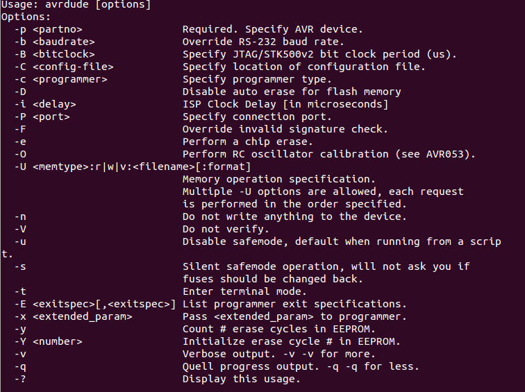
-n Write-nothing mode. This one lets you test out commands without worrying that you’ll accidently mess up the chip.
-c
-p
-t Terminal mode. This mode lets you talk to the AVR chip directly. After the programmer has connected, type sig to read the AVR’s device signature, which makes a quick test of basic communication between the programmer and chip. Type help to see all the options.
-C
-P
-b
-UThis the command that reads or writes to memory. You’ll almost always be calling this from a makefile, but if you’d like to dump the memory
of an AVR chip to a file, or flash in a .hex file that someone has already compiled for you, this is how you’d do it. This sets the baud rate if you’re using a serial programmer. You’ll have to know what speed your programmer wants, or use trial and error.
sudo avrdude -c usbtiny -p attiny44 -U flash:w:led_button.c.hex // For USBTiny
sudo avrdude -c avrisp -p t44 -P /dev/ttyACM0 -b 19200 -U flash:w:led_button.c.hex // For Arduino ISP
Example of flash:
diego@diegoHP:~/led_button$ sudo avrdude -c usbtiny -p attiny44 -U flash:w:led_button.c.hex

avrdude: AVR device initialized and ready to accept instructions

Reading | ################################################## | 100% 0.01s

avrdude: Device signature = 0x1e9207
avrdude: NOTE: "flash" memory has been specified, an erase cycle will be performed
         To disable this feature, specify the -D option.
avrdude: erasing chip
avrdude: reading input file "led_button.c.hex"
avrdude: input file led_button.c.hex auto detected as Intel Hex
avrdude: writing flash (106 bytes):

Writing | ################################################## | 100% 0.07s

avrdude: 106 bytes of flash written
avrdude: verifying flash memory against led_button.c.hex:
avrdude: load data flash data from input file led_button.c.hex:
avrdude: input file led_button.c.hex auto detected as Intel Hex
avrdude: input file led_button.c.hex contains 106 bytes
avrdude: reading on-chip flash data:

Reading | ################################################## | 100% 0.10s

avrdude: verifying ...
avrdude: 106 bytes of flash verified

avrdude: safemode: Fuses OK (E:FF, H:DF, L:62)

avrdude done.  Thank you.
Can check communication with AVRdude command:
diego@diegoHP:~/Collegamento a 211/src/class8/led_button$ sudo avrdude -c usbtiny -p attiny44

avrdude: AVR device initialized and ready to accept instructions

Reading | ################################################## | 100% 0.01s

avrdude: Device signature = 0x1e9207

avrdude: safemode: Fuses OK (E:FF, H:DF, L:62)

avrdude done.  Thank you.
Can also retreive data from flash:
diego@diegoHP:~/led_button$ sudo avrdude -c usbtiny -p attiny44 -U flash:r:mystery.hex:r
I found here a nice tutorial on how to integrate avrdude with Atmel Studio
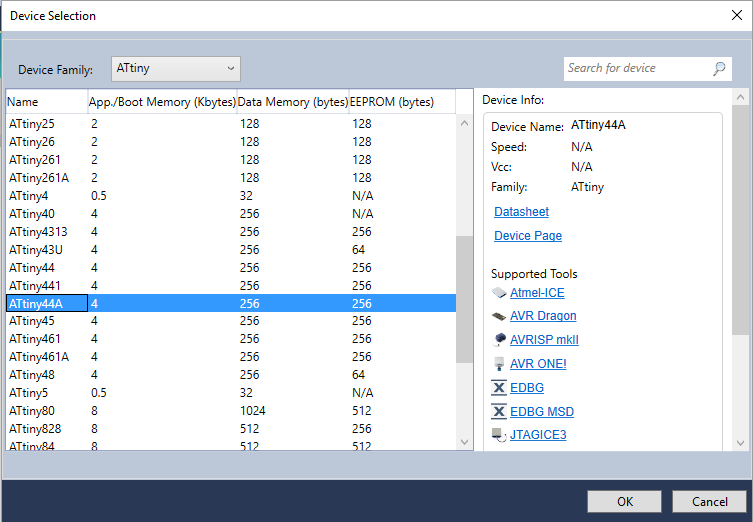
In Atmel Studio create a new project:
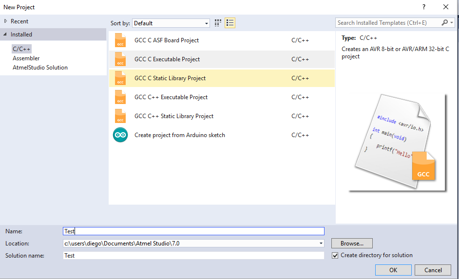
Select board:
Create an external tool from “Tools->External tools” (advanced profile must be active)

-F -c avrisp -p t44 -P COM6 -b 19200 -U flash:w:"$(ProjectDir)Debug\$(ItemFileName).hex":i -C"C:\Program Files (x86)\Arduino\hardware\tools\avr\etc\avrdude.conf"
It is possible also to use an external makefile:
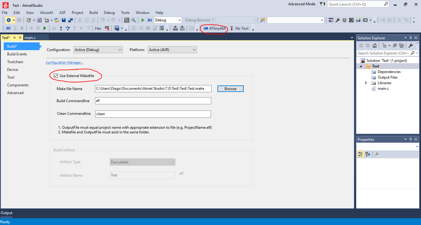
Then Arduino can be used as a programmer:
//Include Files
#include<avr/io.h>
#include<util/delay.h>


//(PCINT10/INT0/OC0A/CKOUT) PB2 - LED
//(PCINT7/ICP/OC0B/ADC7) PA7 - Button

int main(void)
{
DDRB |= 1<<2;       //Declare PB2 as outputs
PORTB |= 1<<2;      //Switch off the LEDs
DDRA &= ~(1<<7);    //Input declared
PORTA |= 1<<7;      //Pull up Enabled
while(1)
    {
        //switch
    if(!(PINA&(1<<7))) //If pressed
        {
        _delay_ms(10);//debounce
        while(!(PINA&(1<<7)));
        //wait for release
        _delay_ms(10);//debounce
        PORTB^= (1<<2);//Toggle
        }

    }
}
Debug hello board:
I started from the Fab Academy tutorial with some small changes mainly about my clock speed which was 1MHz instead of 20MHz in the example.
The example makes a LED blinking using timers instead of delay:
The ATtiny44 has two internal timers that can be very useful in this situation. Timers are registers that increase from zero to 0xFF (255) or 0xFFFF (65535) depending on whether they are 8-bit or 16-bit. When they reach the maximum value, they overflow back to zero and start counting again. With prescalers we can slow down the rate of the timer of 1, 8, 64, 256 or 1024 compared with the clock source using Clock Select bits (CS12:10) in Timer/Counter1 Control Register B (TCCR1B).
To reset the timer at an exact time we use CTC (Clear Timer on Compare) using Waveform Generation Mode bits (WGM13:10) in TCCR1A and TCCR1B To ensure that a signal is received when the timer overflows, the Timer/Counter1 Output Compare A Match interrupt (OCIE1A) bit must be set in the Timer/Counter1 Interrupt Mask Register (TIMSK1).
1 MHz clock speed, Output Compare Register 1 A (OCR1A) to 977
Interrupts must be enabled with sei().
We then include the function that corresponds to the interrupt that we have activated; in this case setting the OCIE1A bit corresponds to the TIM1_COMPA_vect Interrupt Service Routine (ISR). Inside this routine, we simply toggle the LED as before.
//Include Files
#include <avr/io.h>
//#include<util/delay.h>
#include <avr/interrupt.h> // notice that we have swapped libraries, from delay to interrupt
 //(PCINT10/INT0/OC0A/CKOUT) PB2 - LED
//(PCINT7/ICP/OC0B/ADC7) PA7 - Button
int main (void) {
   DDRB |= 1<<2;        //Declare PB2 (LED) as outputs

    sei(); // enable global interrupts

    TCCR1B |= (1 << WGM12); // configure timer1 for CTC mode

// WGM1[1:0]: Waveform Generation Mode
// Combined with the WGM1[3:2] bits found in the TCCR1B Register, these bits control the count-
// ing sequence of the counter, the source for maximum (TOP) counter value, and what type of
// waveform generation to be used, see Table 12-5 on page 108. Modes of operation supported by
// the Timer/Counter unit are: Normal mode (counter), Clear Timer on Compare match (CTC)
// mode, and three types of Pulse Width Modulation (PWM) modes.
//  0100 CTC ( Clear Timer on Compare ) OCR1A

   TIMSK1 |= (1 << OCIE1A); // enable the CTC interrupt
// OCIE1A: Timer/Counter1, Output Compare A Match Interrupt Enable
// When this bit is written to one, and the I-flag in the Status Register is set (interrupts globally
// enabled), the Timer/Counter1 Output Compare A Match interrupt is enabled. The corresponding
// Interrupt Vector (see “Interrupts” on page 47) is executed when the OCF1A flag, located in TIFR1, is set.


   OCR1A   = 977; // set the CTC compare value
   TCCR1B |= ((1 << CS10) | (1 << CS12)); // start the timer at 8MHz/1024
   while(1) { // main loop - do anything you like here!
   }
}

ISR(TIM1_COMPA_vect) { // Timer/Counter1 Compare Match A this function is called every time the timer reaches the threshold we set
   PORTB ^= (1 << 2); // toggle the LED
}
#include <avr/io.h>
#include <util/delay.h>

int main (void) {
   DDRA |= (1 << PA1); // set LED pin as output
   while(1) { // main loop
      PORTA |= (1 << PA1); // switch on the LED
      _delay_ms(1000); // wait a second
      PORTA &= ~(1 << PA1); // switch off the LED
      _delay_ms(1000); // wait a second
   }
}
int led = 1;
// the setup routine runs once when you press reset:
void setup() {
  // initialize the digital pin as an output.
  pinMode(led, OUTPUT);
}
// the loop routine runs over and over again forever:
void loop() {
  digitalWrite(led, HIGH);   // turn the LED on (HIGH is the voltage level)
  delay(1000);               // wait for a second
  digitalWrite(led, LOW);    // turn the LED off by making the voltage LOW
  delay(1000);               // wait for a second
}
I used Arduino to flash my hello board. To make an Arduino an ISP programmer you have to follow these steps (see also this FabAcademy tutorial ):
Upload to an Arduino UNO the ArduinoISP sketch which you can find in File->Examples or you can download from this Adafruit tutorial .
Connect Arduino pins 10:13, as follows (also Vcc and GND obviously)
// 10: slave reset
// 11: MOSI
// 12: MISO
// 13: SCK
sudo avrdude -c avrisp -p t44 -P /dev/ttyACM0 -b 19200 -U flash:w:led_button.c.hex
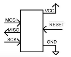
I was cheated by this image at page 8 of “AVR Projects for evil genius” which is about “ISP” signal. I made wrong connection with my hello board and I wasn’t able to program it.
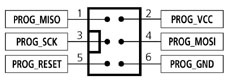
This is the right pinout for SPI connector:
The temperature measurement is based on an on-chip temperature sensor that is coupled to a single ended ADC8 channel. Selecting the ADC8 channel by writing the MUX[5:0] bits in ADMUX register to “100010” enables the temperature sensor. The internal 1.1V reference must also be selected for the ADC reference source in the temperature sensor measurement. When the temperature sensor is enabled, the ADC converter can be used in single conversion mode to measure the voltage over the temperature sensor.
ArduinoISP Tutorial
Hello Board sources and schematics
Make: AVR programming
TinyAVR projects for evil genius
AVR Libc (avr specific libraries)
Gnu wiki on avr-gcc
AVRfreaks, a community around the avr chips
A demo project from nongnu
Avrdude on windows