Table Of Content
I used Rhino to model my “big” project.
First I made a smaller model on 1:10 scale in order to make a test cut and assembly with laser cut and thin plywood.
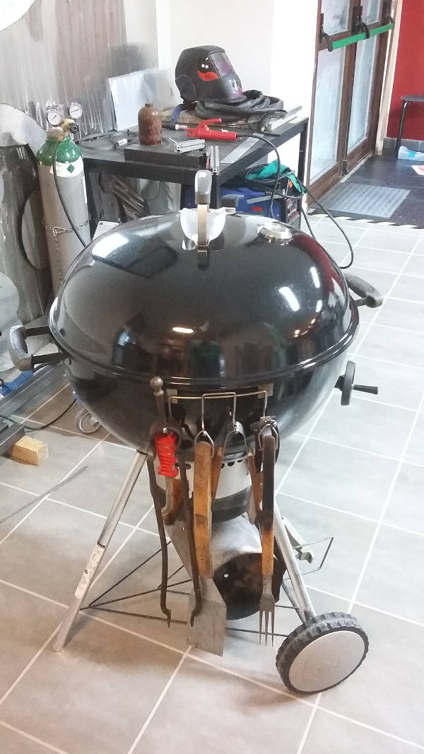
I decided to make an outdoor barbecue table for FabLab Cascina, since we are used to have BBQ each and every Sunday but our Barbecue comes without any tray attached making very annoyng to handle food while cooking.
I tried to follow some basic design requirement:
- Minimize waste (use as much as possible the 240x120 cm OSB available)
- Simple Joints
- Minimum number of pieces (3-4 repeated figures)
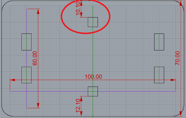
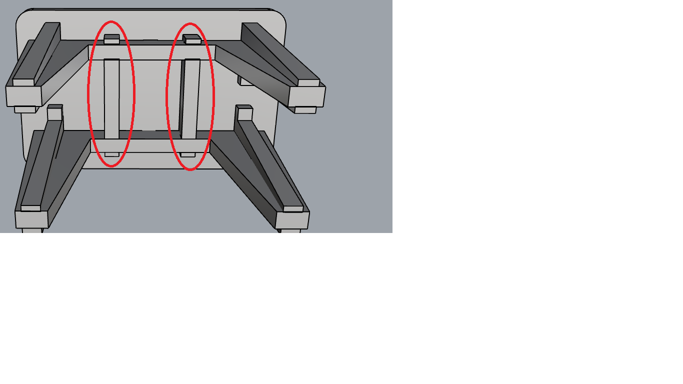
I made a first check of the design with a 3D model on Rhino (especially the assembly). That happened to be useful since I found an error this way:

Then I came back to the 2D model in order to identify the error and fix it.
This is the resulting 3D model:
After I double checked the 2D design with 3D model I exported to .DXF and then I imported it on Illustrator. There I made little changes to line colours and external boundaries. I double checked that Illustrator correctly imported dimensions.
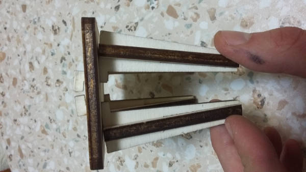
Before going to the milling machine I made a small scale test with the laser cut and 6 mm Plywood. The piece of table I used was very curved, so I needed to redo the cut 4 times before getting nice cuts:


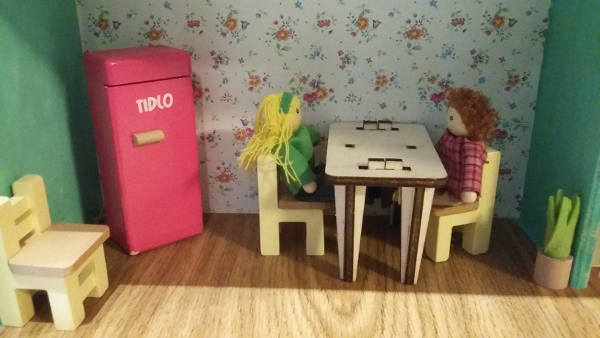
Finally the small scale sample was assembled, everything fits nicely:
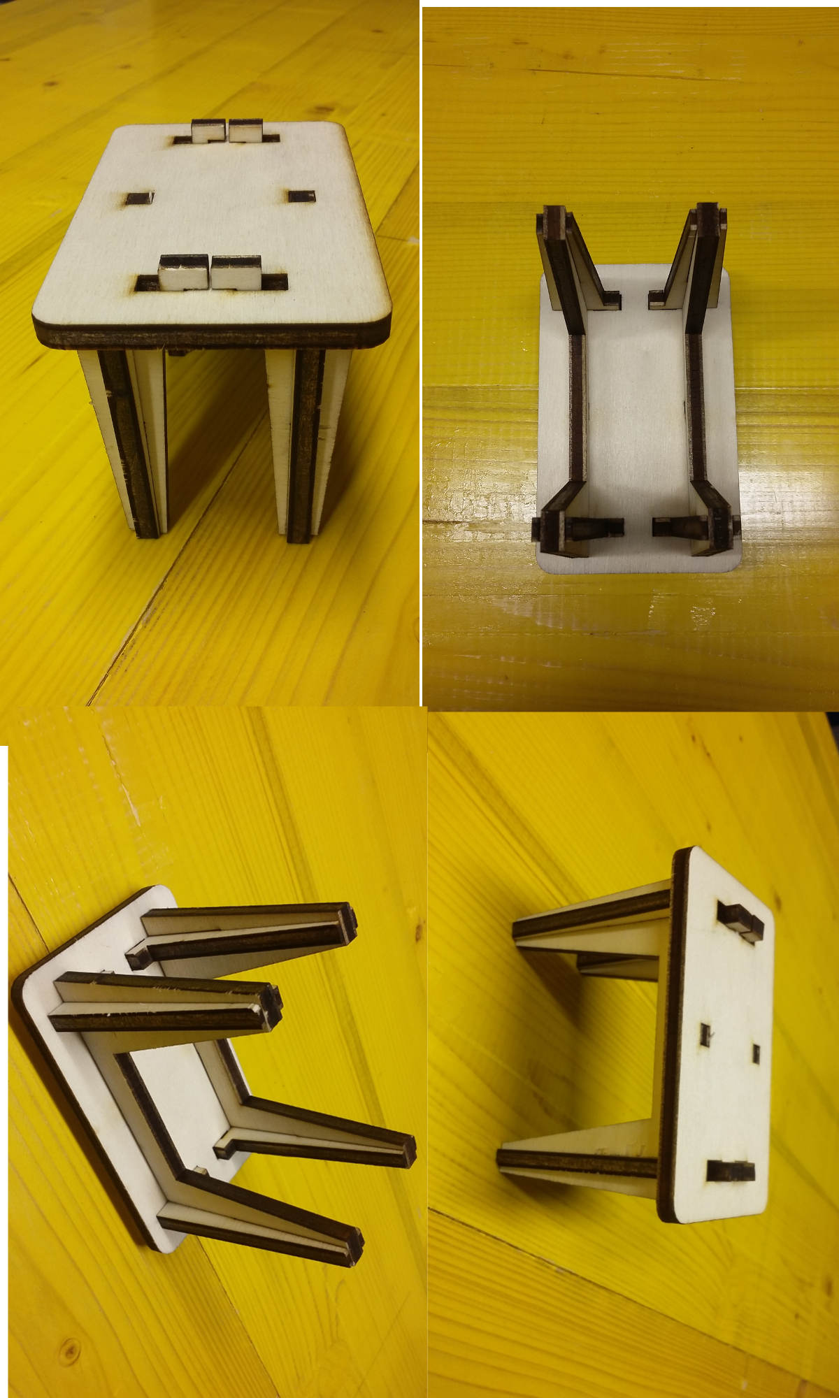
I noticed that table legs are not very strong when pushing them toward the inside of the table.
Thus I did one more CAD iteration adding two pieces of material behind the table in order to strenghten it:
In the end the small scale sample was also a nice toy for my kids
EDM wire machine
- Rigid foam
- Compressed styrophone
- Rigid foam insulation (gesso, heat gun)
- Veneer plywood
- Medium Density Fiberboard (MDF) releases toxic gas
- Medium Density Overlay (MDO)
- Oriented Strand Board (OSB) cheap
- HDPE
- Lexan, polycarbonate
- Garolite
- Aluminum
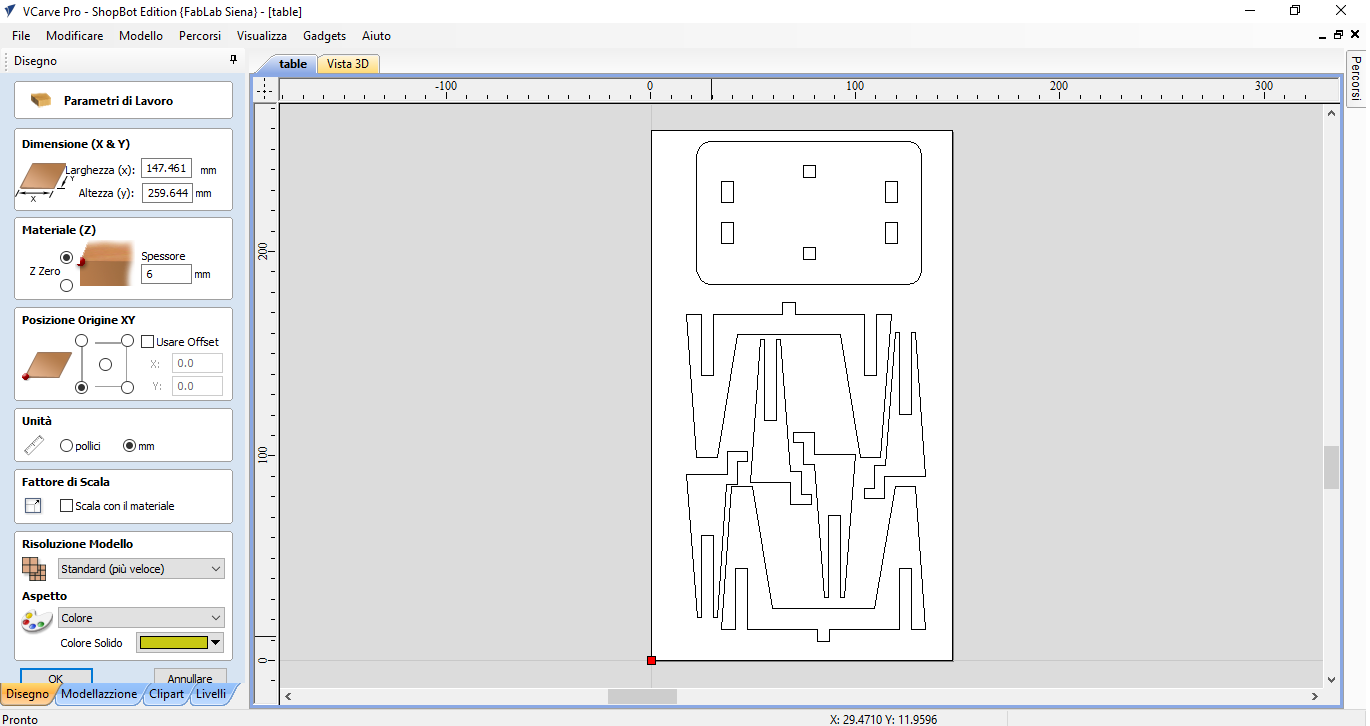
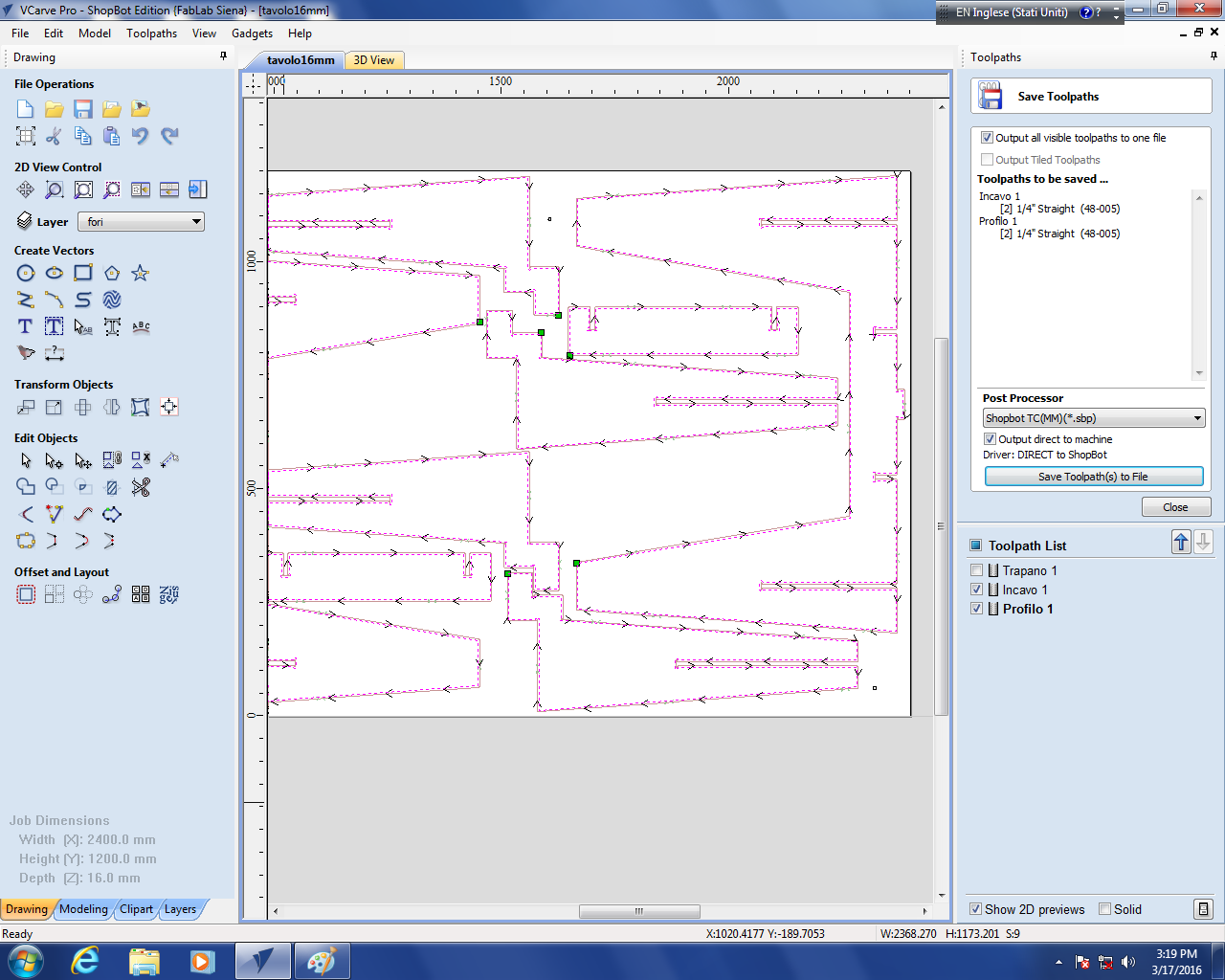
In Fab Lab Siena we have a Shopbot, so we used the Shopbot Software to generate the Machine file.
The software is similar to the Laser cut one (colours can be used for different jobs), but with many more options.
Job phases:
- Holes (holes are of the size of the tool)
- Pockets (all the material inside a perimeter is milled)
- Profiling (cut through). Can be externa, internal or on the line cut.
First, we have to set the Job area and coordinate origin (in our Shopbot we have the origin on bottom right and y goes horizontally). Z can be measured on the plane or on the board. On the board is more convenient when the job needs different tools since we have to redo Z calibration after each tool change.
Set units to mm. The software can import DXF (maintain layer colours) or 3D files (like .STL).
There is also a tools palette to draw directly in the shopbot program (very handy to make test cuts or simple panels).
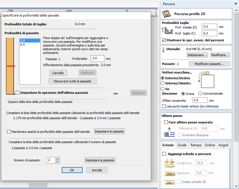
The number of passes can be changed. It is possible also to leave a thin layer of material in order to keep internal wood pieces attaches to the rest of the board and avoind that they fly away. Usually the cut depth is of the same size of tool diameter.
Holes settings:

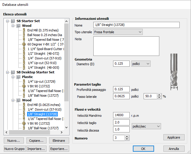
Thypes of milling tools:
- One of the most versatile tools is the 1/8 = 0.125 inch = 25.4/8 = 3.17 mm.
- 1/2 tools are good for fast roughing cuts (less passes).
- 1/16 = 0.0625 is for precision finishing jobs. (1/2 and 1/16 can be used for 2 phases jobs: roughing and finishing)
- Other tools
Feed speed:
- Milling speed
- Cut speed
See the tool reference for detail settings.
Feed rate calculator shopbot
(OSB = Soft Wood)
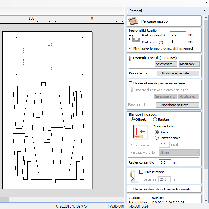
Pocket milling:
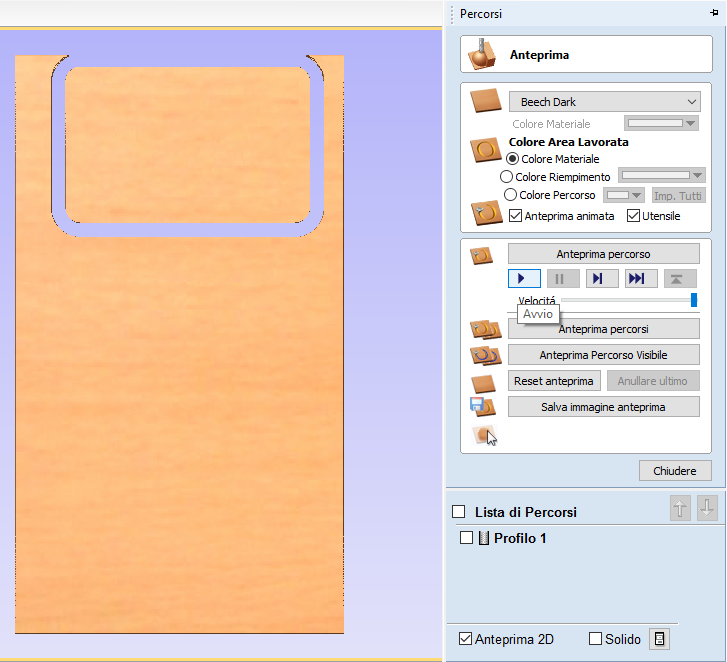
The software generate a 3D and video preview in order to show the milling paths and final result (useful to chose a milling tool for 3D or special jobs)
After everything is set, we should export the “.SBP” machine file which should be inspected with a text reader in order to make a final check of basic parameters like units, dimentions, milling tool…
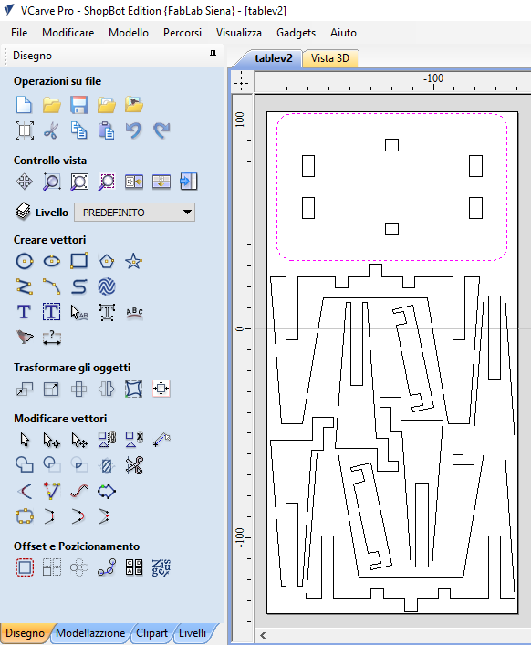
I added 4 holes for screws with the V-Carve editor as a new layer. Then I created 3 Jobs:
- Drilling for screws holes
- Pocket for the holes on the table
- Profiling for all the rest
I used a 1/4=0.25 inch = 0,635 cm straight tool for this reason I added 7 mm “dog bone” where needed to my model. Tool Speed: 18000.

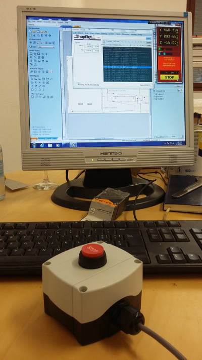
First select the toolpath for the screwdriver and send it to the machine. I used 4 screws at the 4 angles of the board
The whole job took around 40 minutes (3 passes @ 100 inches/min). I standed all the time next to the stop button:
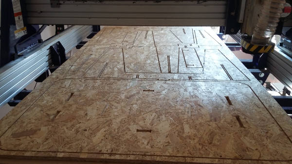
I used almost all the board:

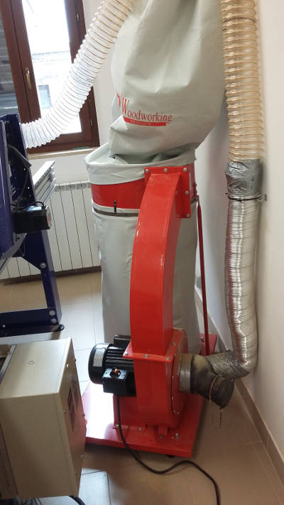
The vacuum system is very noisy:
First I dismounted from the board all pieces of my table:

As I planned there were very few wastes:
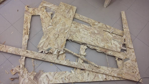
I had a lot of finishing work to do since 1mm of material on almost all the board was not removed, maybe for a wrong Z-calibration or tolerance of board width.
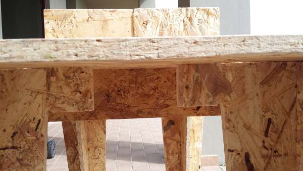
Pockets perfectly fit with other pieces thanks to the dogbone (circles of the same size of the tool)

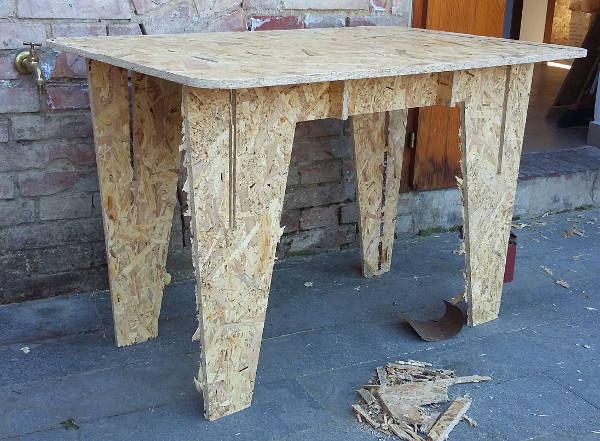
Moving the pieces of the table from Siena (where the Shopbot is) and Cascina (my Fab Lab) I broke a piece in the position of a pocket. Lesson learned: don’t remove too much material in long and thin parts.

Anywat the table have sufficient joints to keep standing even with that broken part.
All parts fitted correctly. There is no need to consider kerf like laser cutter: the tool respect a boundary from the inside or the outside

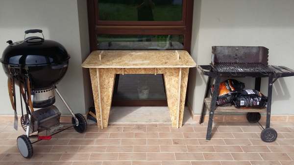
The table ended up to have a nice prospective with the environment
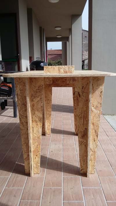
It is time for the final stress test for which we need an actual hero, who better than a FabLab student??

And finally the brand new BBQ table is in place and ready for gorgeous FabLab dinners
PDF model
DXF model
V-Carve file
ShopBot Speed Charts