Table Of Content
I used Eagle (very common in Open projects, free with limit in board size, cross platform, extensible, click and drag) among many electronics CAD (Virtual breadboard, 123D tool, Fritzing, Mouser,design spark, circuit maker and pcb works which integrate also a 3D CAD) to redesign the Hello World board following these steps:
- Place comp
- Draw schematics
- Make connections
- Simulate (optional)
Instead of click and drag some CAD write a series of relationship
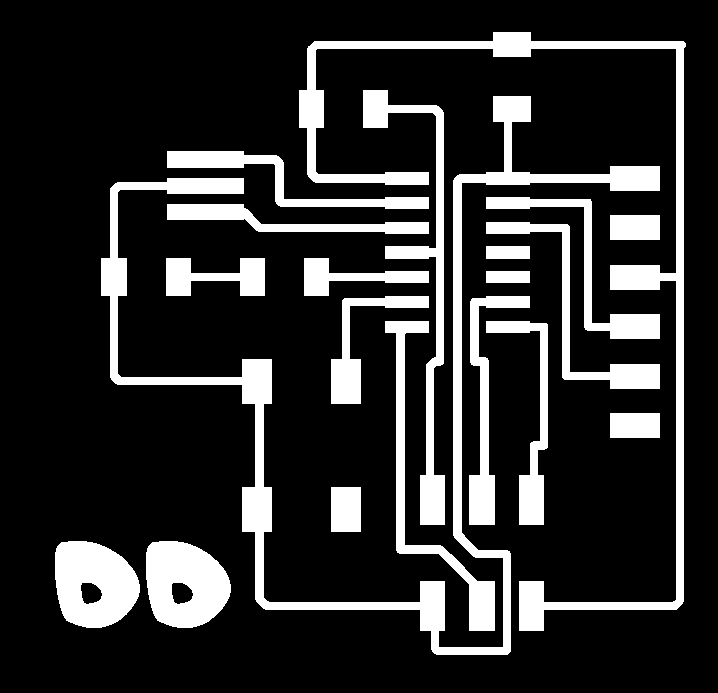
Files that describe a board are .brd and .sch, moreover Gerber is sort of Gcode for milling machine.
Notes on board design: It is very common to find a capacitor between VCC and GND, it works as a filter and local storage. There is also a pull-up resistor on pin1 which tells the micro to start. Before the power regulator there is usually a protection Diode.
I added to Eagle
Fab
and
Sparkfun
libraries to get the parts that I needed.
sudo cp /home/diego/01_SparkFun.lbr /home/diego/.eagle/lbr/
Notes on Eagle:
- Auto routing good for complex boards
- Design rule check before milling (Laser cut is more precise than milling machine but it cannot do drilling)
- When moving an object right click rotate
- Add a library
- Add open the library (choose SSU package)
- Replace (good for connectors)
- Clone symbols (can use to separate functional blocks)
- View-> grid (Size: 0.025, Alt: 0.0125 inch) even less to place very precisely paths.
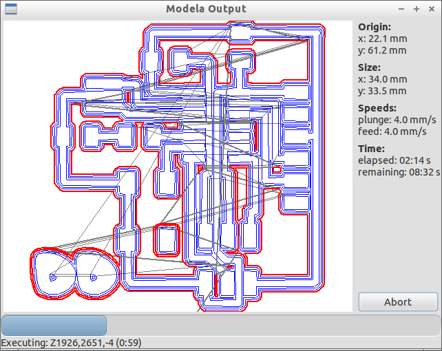
- To export a .png: View-> Layer setting, Select none and then select top. File-> export image monochrome 1000dpi
- Do the same for dimension layer to export etching
- Control design rules: Tools -> ERC () and DRC (Design Rules Check) Clearance is 16 mills (1/1000 of inch) for drilling machine. Commercial board manufacturer publish their Design Rules (Oshpark is a PCB buying group which optimize minimum size of boards)
- Can edit .png on GIMP to fix it.
- To create the border open the etching .png in GIMP add 20px to the width (linked proportions) and center, then flatten the image
- Ripup to cancel path
- .dru files saves design rules
- grove conncetor (as Little bits)
The Hello Board is based on an ATtiny 8 bit AVR, which is very cheap (1-2 dollars), can run at 20MHz (enought to sample sounds)
Families of ATtiny are 24, 44, 84 which have same pins and registers, only changes available memory for programs.
45 family (2-3$) have same charachteristics as 44 but less pins
Atmega328p (Arduino) and Xmega have more interrupts and wires, but same principles of smaller ATtiny
For projects and products that are supposed to las many years it is important to make sure about the availability of conponents: Seed studio have a open part library for parts with guaranteed availability
To understand how to use a new component search (
Octopart
) the datasheet and go to the pin config page.
Pins
ATTiny have 2 ports A and B (Arduino created a logical layer for “analog” and “digital” pins which is an abstraction). ATmega has 4 ports, Xmega 8, etc…
Each port can handle max 8 pins due to a 8 bit register. Note: be aware of pin name vs pin number which could be misleading.
Reset is usually connected to VCC, if it is low for a clock cycle the micro reset
SPI pins are MISO, MOSI, VCC, GND, etc…
More complex micro have HW serial TX and RX , we emulate serial protocol in SW using timing instead dedicated HW.
PB0:xtal1 and PB1:xtal2 can be used for for external clock. if you don’t have external can use these pins for other tasks.
8 pins can be used for analog inputs since they are connected to Analog Digital Converter.
Timers: t0 and t1
Comparators: oca ocb
Interrupt: To trigger events (for example button push) can use polling (a SW routine listen periodically to a pin) or interrupt (a value change in a pin triggers an interrupt). Almost all a-pins can be used to do HW interrupt but INT0 and INT0 enable external interrupt (powerful because the change can be rising or lowering value)
From the original design of the Hello Board I removed the pull up resistor bacause attiny has already one. Also I did not soldered the resonator since right now I don’t need much speed (in make files I have downgraded the CPU speed and increased serial communication delay).
In FabISP a quarz crystal is needed to have enough precision for USB communication (resonator 5% precision vs quarz 1 % precision). Quarz have capacitor resonator don’t.
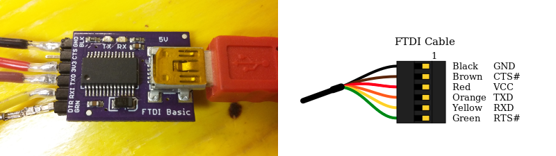
FTDI
FTDI is a patented serial-USB converter. It is fast (300 to 3M baud). Can be used as TTL rs232 rs482. There are some usb cable with FTDI inside (cost a lot)
Black = first pin. FTDI cable brings power.
TXD and RXD are referred to the computer so need to connect vice versa to the target
CTS and RTS used for flow control (not always needed).
To start a new project a good idea is to go to Sparkfun, download a board and see which component are used instead of starting from scratch looking for components.
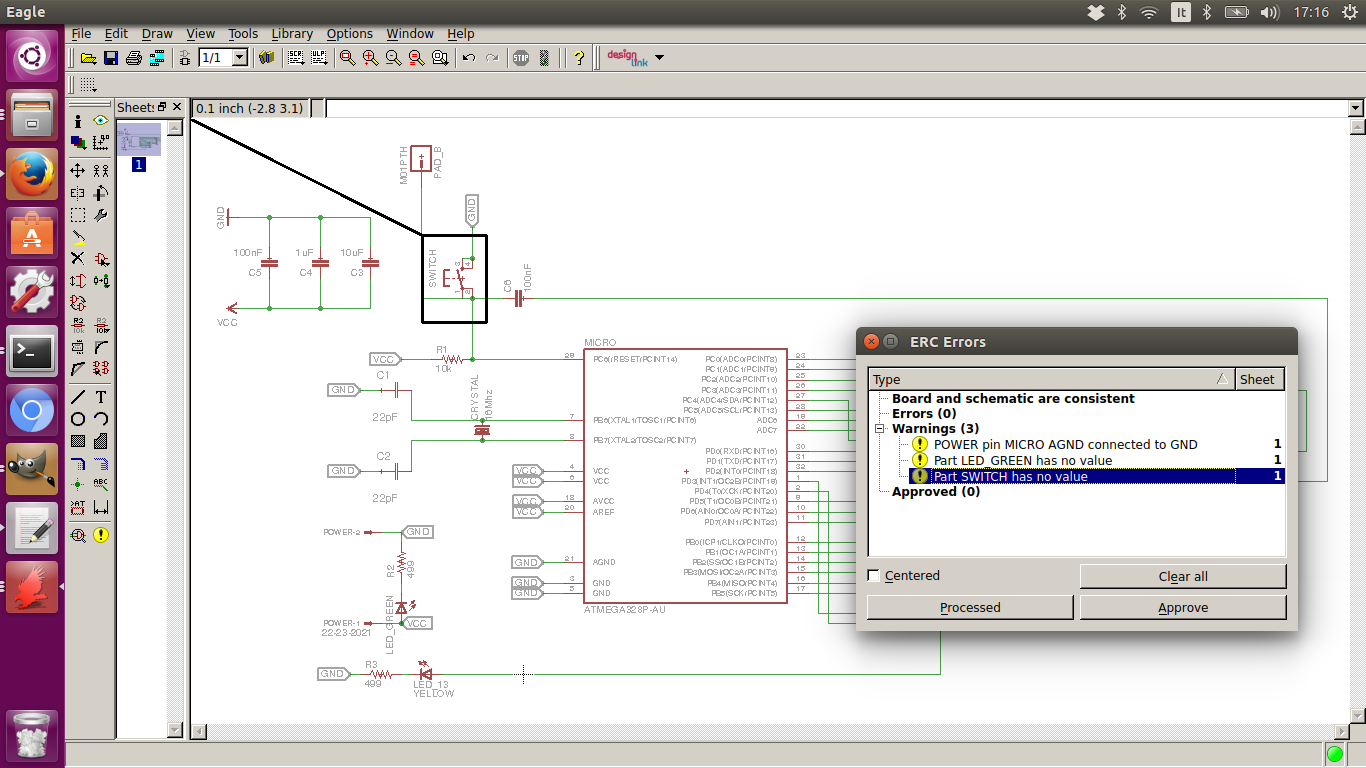
In eagle I started placing components in Schematic Window using the reference board in the tutorial and picking components from the Fab library.
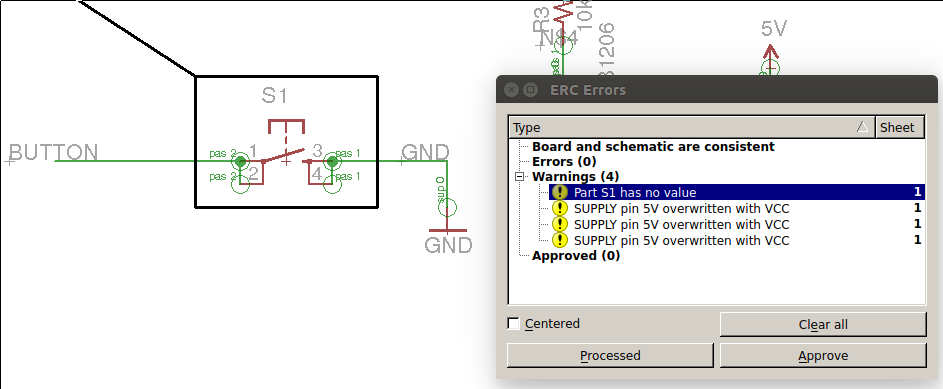
I ran ERC tool which highlighted some wrong connections (name mismatch)
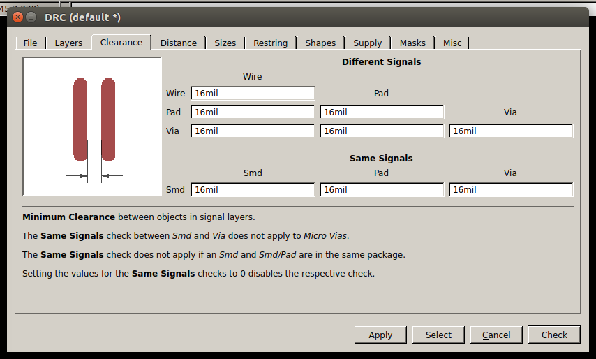
Then I set clearance as the Design Rules of our Roland MX 20 Milling machine
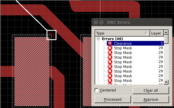
Running DRC tool I found many issues to be fixed, in particular paths under the micro required a very precise positioning and a grid size of 0,01 inches
In GIMP I edited the image to add my initials
Then I added a 20px frame to be used as cutting path

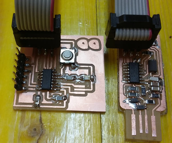
Milling the board:
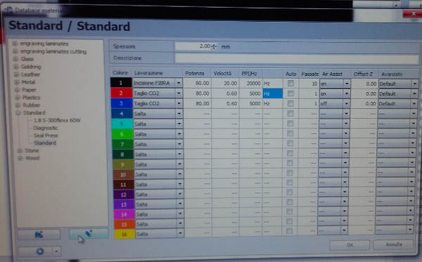
We tested the Laser cut machine for etching but it was quite slow and useless for the precision of this boards:
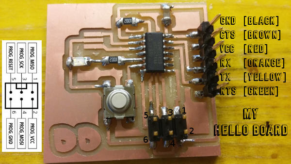
Final result, my Hello Board:
~/Fab Academy/hello_world$
sudo make -f hello.ftdi.44.echo.c.make
sudo make -f hello.ftdi.44.echo.c.make program-usbtiny
sudo miniterm.py /dev/ttyUSB0 115200
I had an issue with serial communication speed, both 115200 and 9600 bps weren’t working since there was a wrong delay in my “hello.ftdi.44.echo.c”. I am not using resonator so the micro must work slower because its internal clock is not precise enough to run seria communication at full speed. In “hello.ftdi.44.echo.c” I had to change:
#define bit_delay_time 102 // bit delay for 9600 with overhead
And in the make file I put 8MHz instead of 20MHz as CPU speed:
PROJECT=hello.ftdi.44.echo
SOURCES=$(PROJECT).c
MMCU=attiny44
F_CPU = 8000000
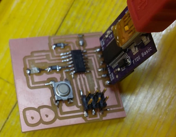
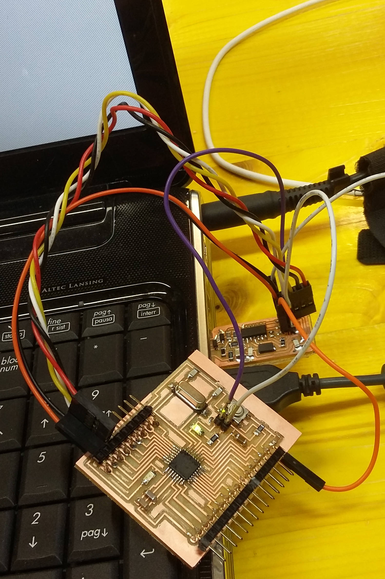
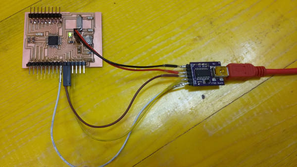
Uploading the bootloader with my ATtiny programmer and a SPI cable
Testing the board connected with a FTDI cable
At a first attempt to communicate with the Hello Board I didn’t realize that I had put a delay of 15 instead 102
sudo miniterm.py /dev/ttyUSB0 9600
--- Miniterm on /dev/ttyUSB0: 9600,8,N,1 ---
--- Quit: Ctrl+]  |  Menu: Ctrl+T | Help: Ctrl+T followed by Ctrl+H ---
�����N����Nttn����N�z@���@�����@B�������Hb
�����n����NttN����N�z@���@�����`b�������Hb
�����n����NttN����N�z@���@�����@B�������Hb

--- exit ---
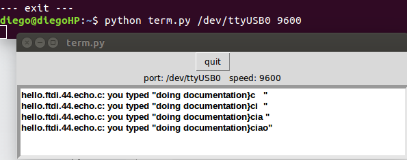
Then after I fixed the correct delay and flashed again the Hello Board with my ATtiny programmer I got:
sudo miniterm.py /dev/ttyUSB0 9600
--- Miniterm on /dev/ttyUSB0: 9600,8,N,1 ---
--- Quit: Ctrl+]  |  Menu: Ctrl+T | Help: Ctrl+T followed by Ctrl+H ---
hello.ftdi.44.echo.c: you typed "                        "
hello.ftdi.44.echo.c: you typed "d                       "
hello.ftdi.44.echo.c: you typed "do                      "
hello.ftdi.44.echo.c: you typed "doi                     "
hello.ftdi.44.echo.c: you typed "doin                    "
hello.ftdi.44.echo.c: you typed "doing                   "
hello.ftdi.44.echo.c: you typed "doing                   "
hello.ftdi.44.echo.c: you typed "doing d                 "
hello.ftdi.44.echo.c: you typed "doing do                "
hello.ftdi.44.echo.c: you typed "doing doc               "
hello.ftdi.44.echo.c: you typed "doing docu              "
hello.ftdi.44.echo.c: you typed "doing docum             "
hello.ftdi.44.echo.c: you typed "doing docume            "
hello.ftdi.44.echo.c: you typed "doing documen           "
hello.ftdi.44.echo.c: you typed "doing document          "
hello.ftdi.44.echo.c: you typed "doing documenta         "
hello.ftdi.44.echo.c: you typed "doing documentat        "
hello.ftdi.44.echo.c: you typed "doing documentati       "
hello.ftdi.44.echo.c: you typed "doing documentatio      "
hello.ftdi.44.echo.c: you typed "doing documentation     "

--- exit ---
I also used the terminal provided by Fab Academy to do the echot test with the Hello Board:
python term.py /dev/ttyUSB0 9600
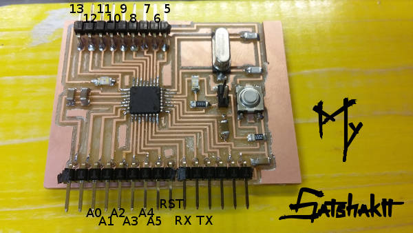
Satshakit
is a Fabbable Arduino IDE compatible board.
ERC was ok for the board:
But in order to make the board compliant with design rules of our milling machine I had to split 14 pins connector in 5+9 pins and to reduce the size of a line from 12 to 10 mills.
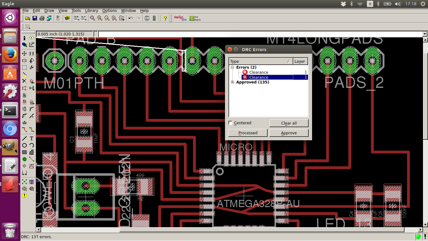
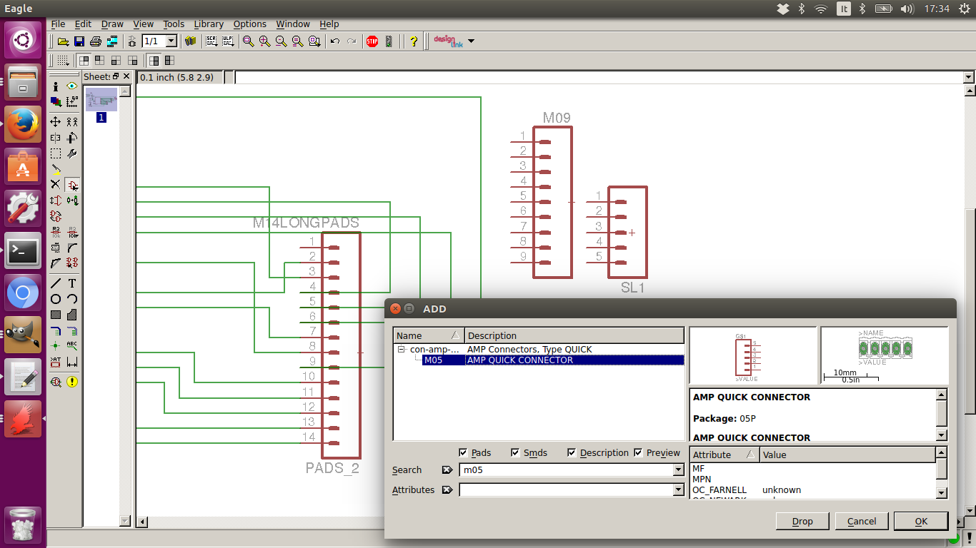
Added a couple of new pin strips from Sparkfun Library:
New connectors were positioned close but with a bit more distance from the trace in between
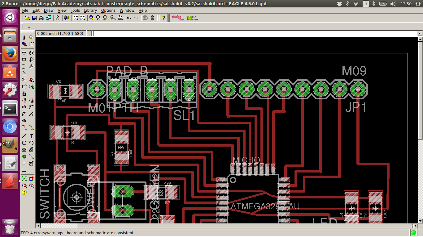
To export images for the milling machine I had to add the “pads layer”:
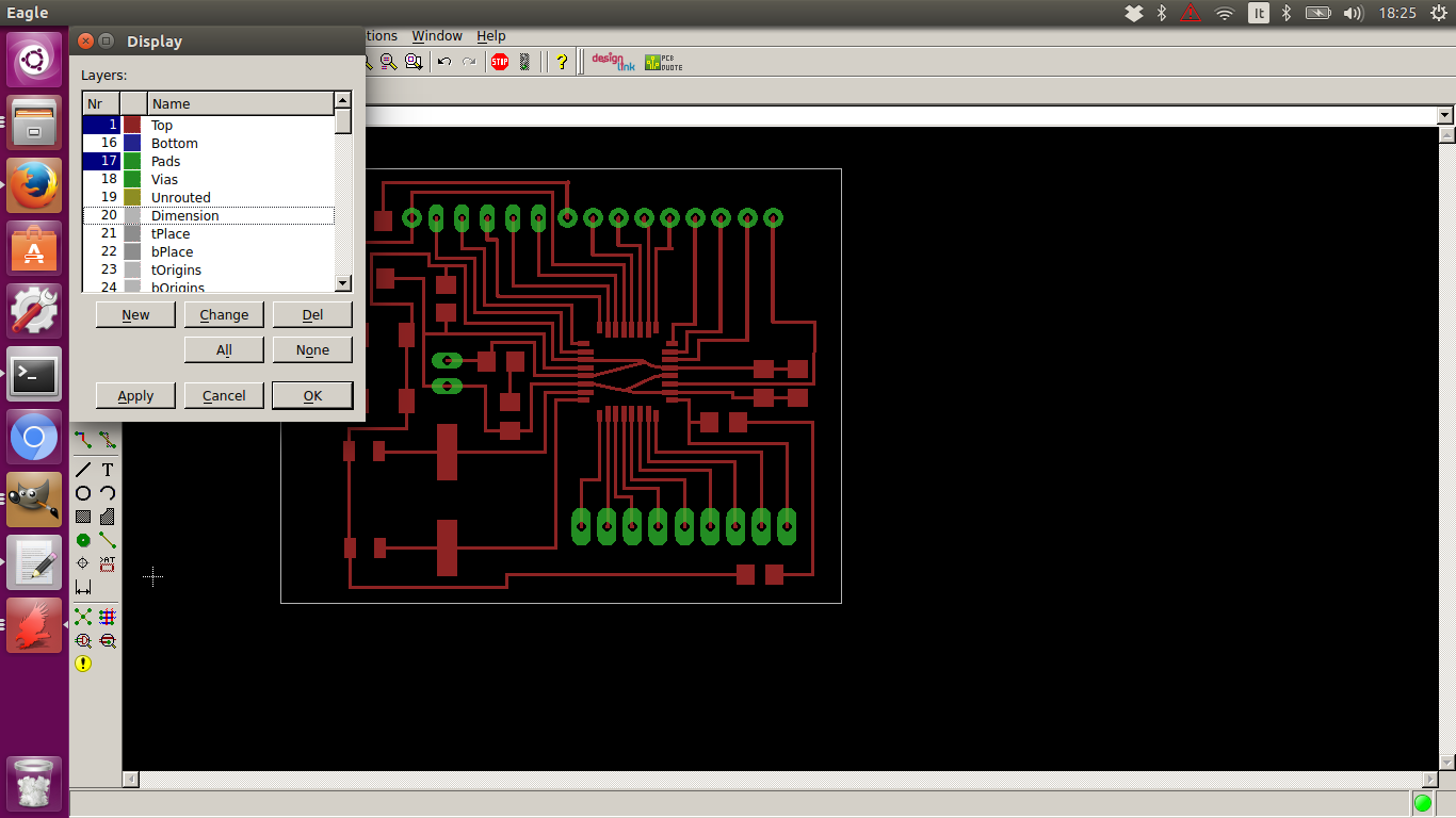
Etching image (traces+pads)
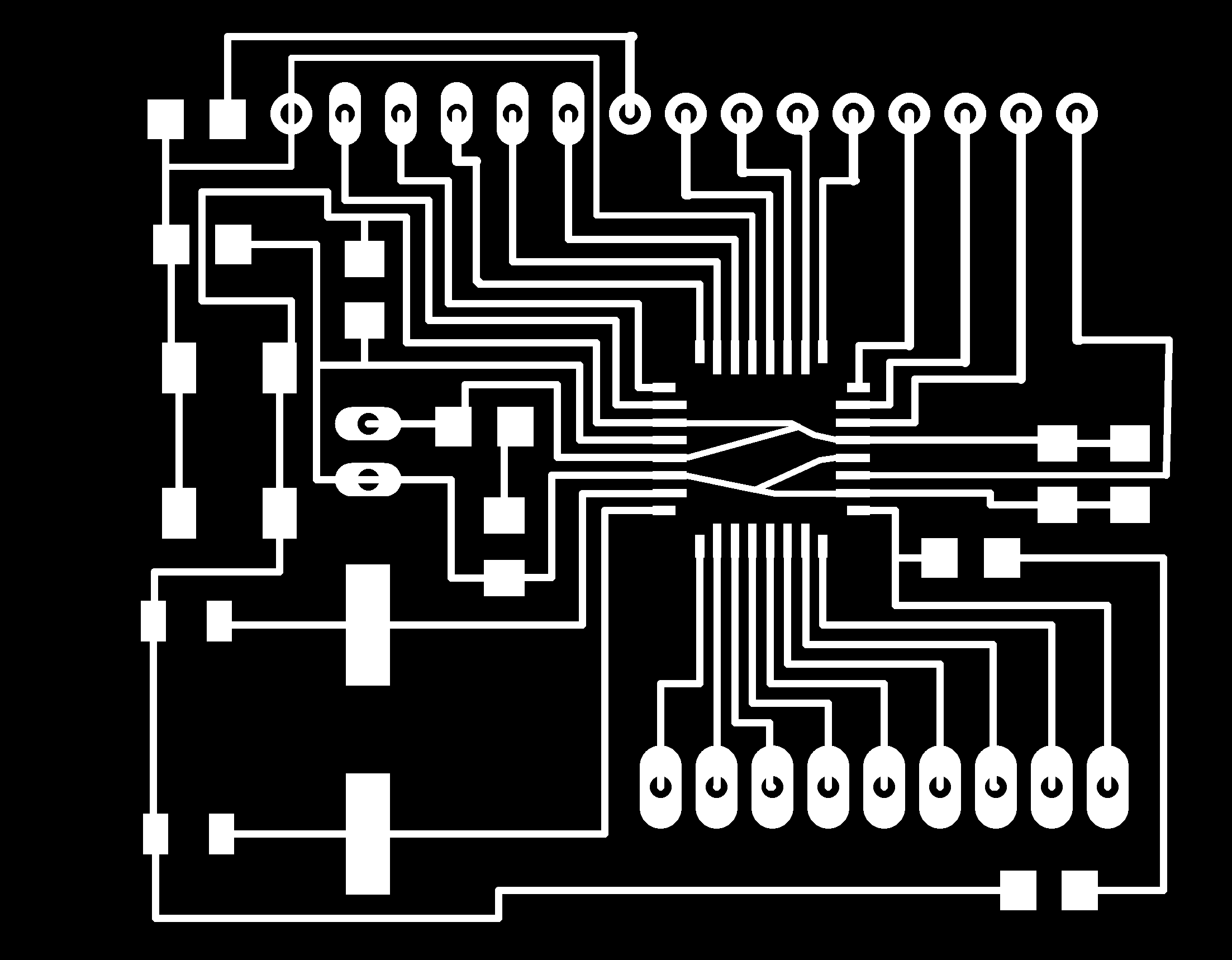
And I had to export a separate image for the holes (done with GIMP):
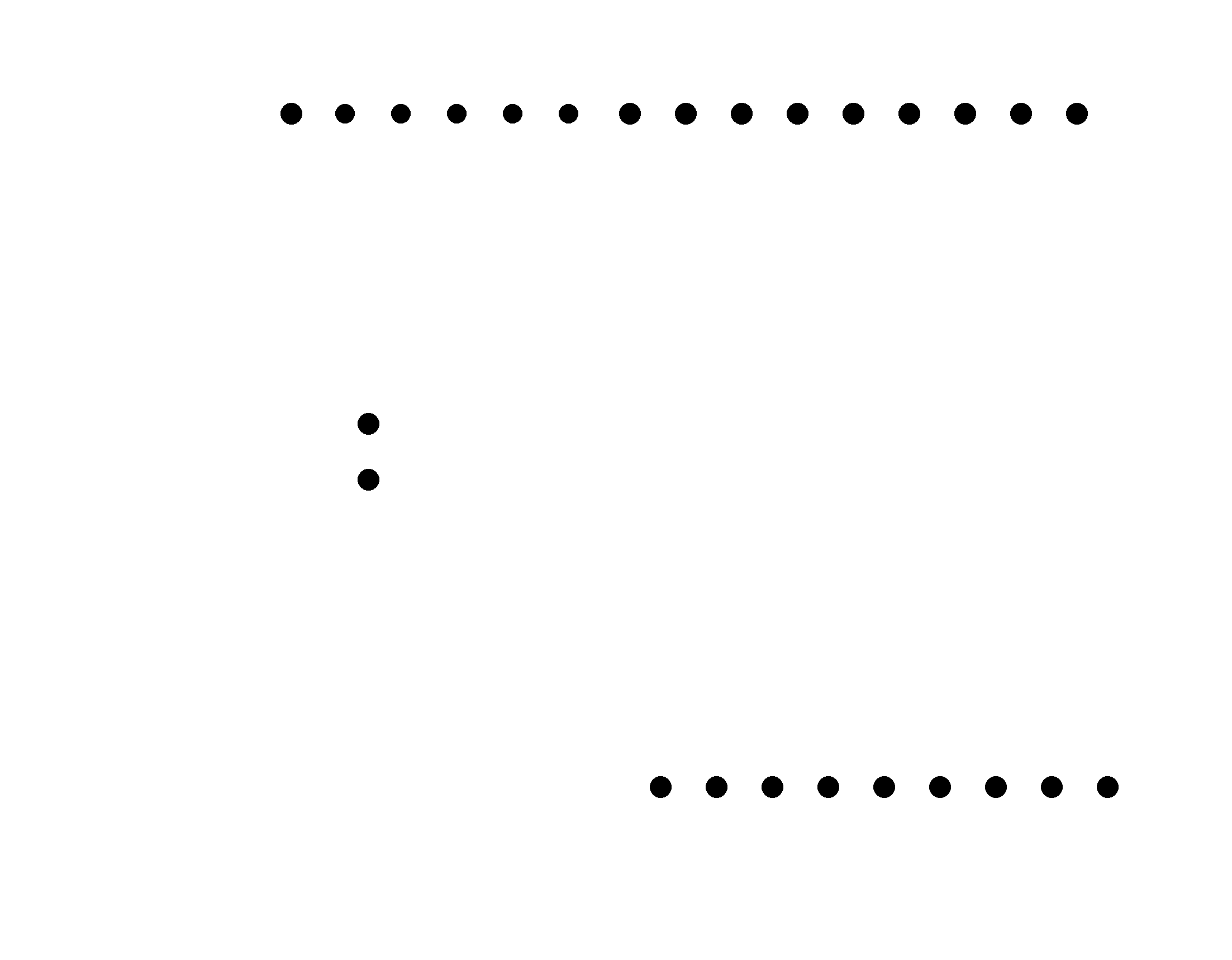
Holes and border use the same 1/32 tool I needed to run two separate jobs since board cutting must be the last operation

Soldering was a very slow job since I preferred to chech each and every connection step by step to avoid short circuit. I made some use of flux but patience was my real weapon in this fight
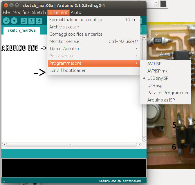
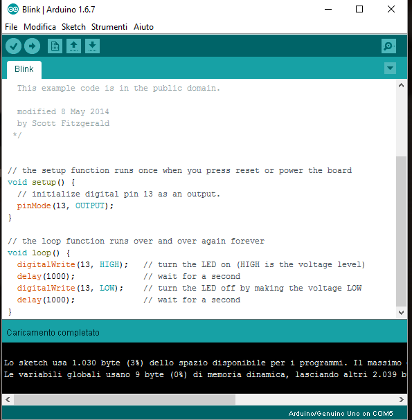
I programmed the board uploading the bootloader using the Arduino IDE (Linux 2:1.0.5) setting “Arduino UNO” ad board, “USB Tiny” as programmer:
I used the wiring described in the Satshakit website:
This operation was successful, then I uploaded a Blink example again using the programmer (it can be used to upload sketches pressing shift while clicking on upload in the Arduino IDE). It worker but this was not a complete test since this way the bootloader don’t run 8the sketch is uploaded directly from the programmer).
I tried to upload a sketch using a FTDI cable connected as indicated in the Satchakit web page but it didn’t work on linux. I had to try many thimes and in the end it worked with a Windows Arduino IDE v1.6.7
Hello Board sources and schematics