Make an in-circuit programmer (FabISP)
I chose
Andy
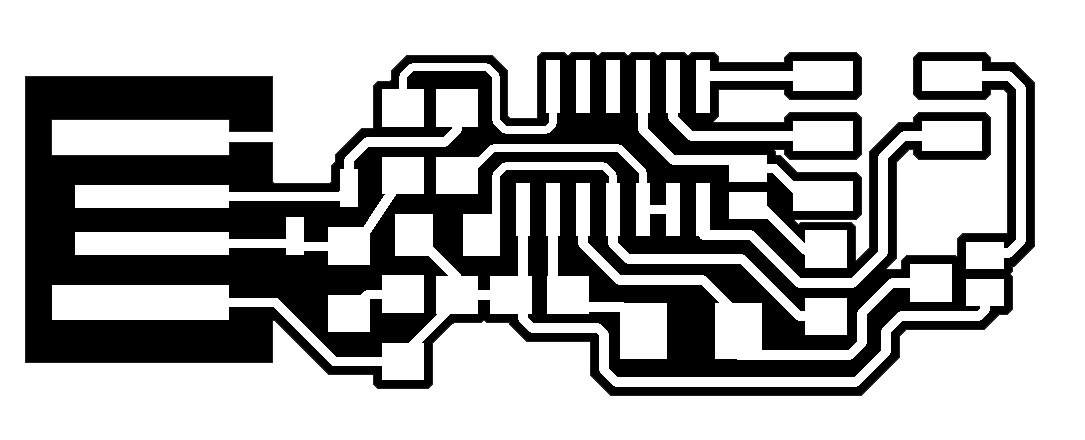
Fab ISP Key since I enjoyed its PCB-USB connector design.

| Part | Value | Device | Package | Library |
|---|---|---|---|---|
| C1 | 8p | C-USC1206 | C1206 | rcl |
| C2 | 8p | C-USC1206 | C1206 | rcl |
| C3 | 0.1u | C-USC1206 | C1206 | rcl |
| C4 | 1u | C-USC1206 | C1206 | rcl |
| D1 | 3.3 | ZENER_DIODESOD123 | SOD123 | fab |
| D2 | 3.3 | ZENER_DIODESOD123 | SOD123 | fab |
| IC1 | ATTINY44-SSU | ATTINY44-SSU | SOIC14 | fab |
| J1 | SJ | SOLDER_JUMPER | SJFAB | fab |
| J2 | SJ | SOLDER_JUMPER | SJFAB | fab |
| R1 | 49.9 | R-US_R1206 | R1206 | rcl |
| R2 | 49.9 | R-US_R1206 | R1206 | rcl |
| R3 | 1K | R-US_R1206 | R1206 | rcl |
| R4 | 10K | R-US_R1206 | R1206 | rcl |
| R5 | 0 | R-US_R1206 | R1206 | rcl |
| R6 | 499 | R-US_R1206 | R1206 | rcl |
| X1 | USBPCB | USBPCB | USB-A-PCB | SparkFun |
| X2 | AVRISPSMD | AVRISPSMD | 2X03SMD | fab |
| XTAL1 | 20MHz | CRYSTAL | 2-SMD-5X3MM | fab |
I installed Eagle to open schematic and board diagram:
sudo apt-get install eagle
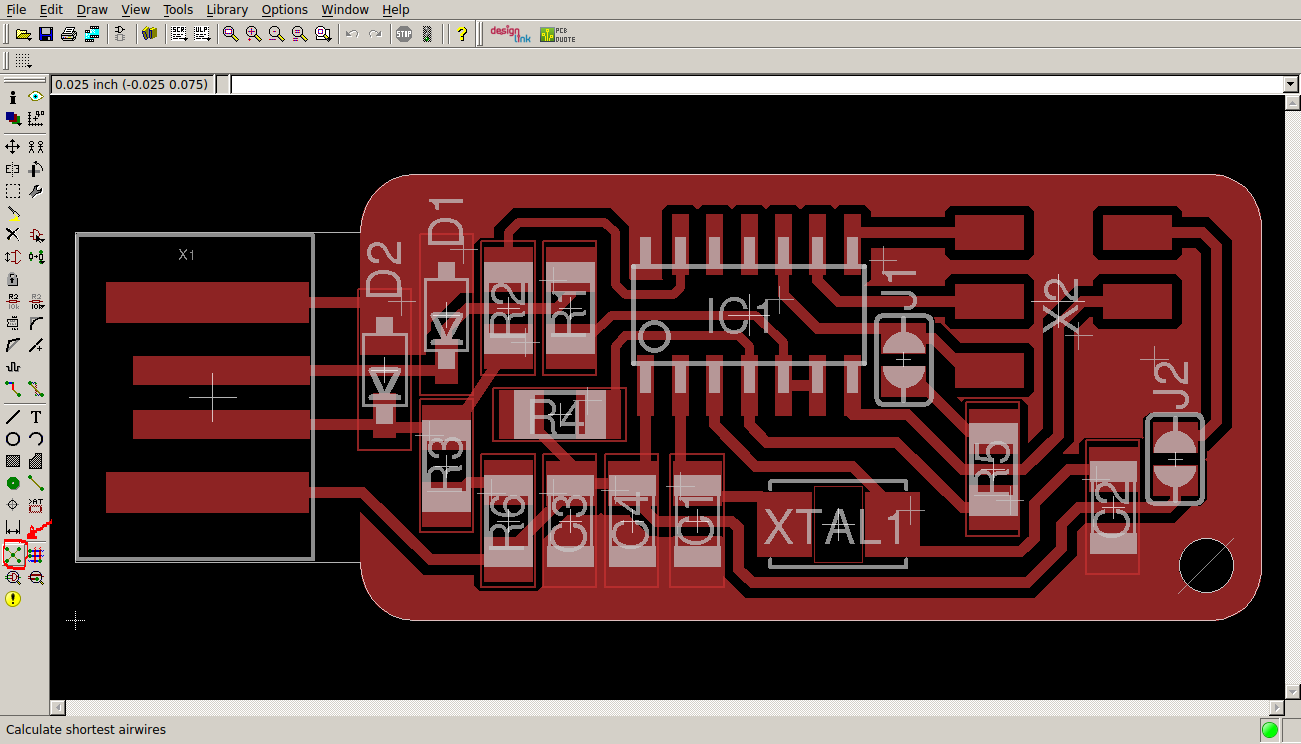
In Eagle it is possible to add a ground pour with the “Ratsnest” command.
Then I used an old local version of Fab Modules to process .png files of my board:
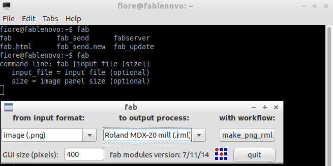
This old Fab Module interface works similar to the web one: select an input format, then an output format (Roland MDX-20 mill .rml) then a process.
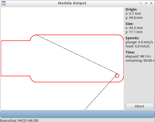
To mill out traces I used “mill_traces 1/64” and to drill the board I used “cut out board 1/32”.


Make path, move XY, make rml, then start job.
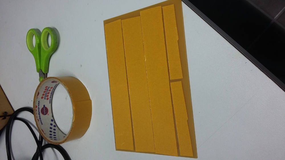
I used a double side tape to glue my PCB to another PCB to be used as working table.
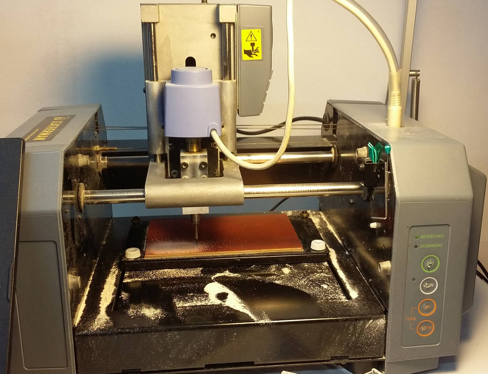
The milling machine is a Roland MDX-20. An old machine which still do its job pretty well.
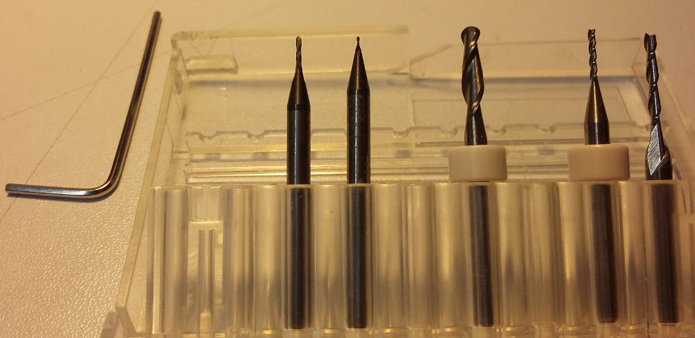
1/64 drilling tools are for traces, 1/32 drilling tools are for cutting.
To change a tool:
Milling traces
Drilling board
We made two board in series, the first set at xy(5,5), the second at xy(5,27) since dy=18.6.
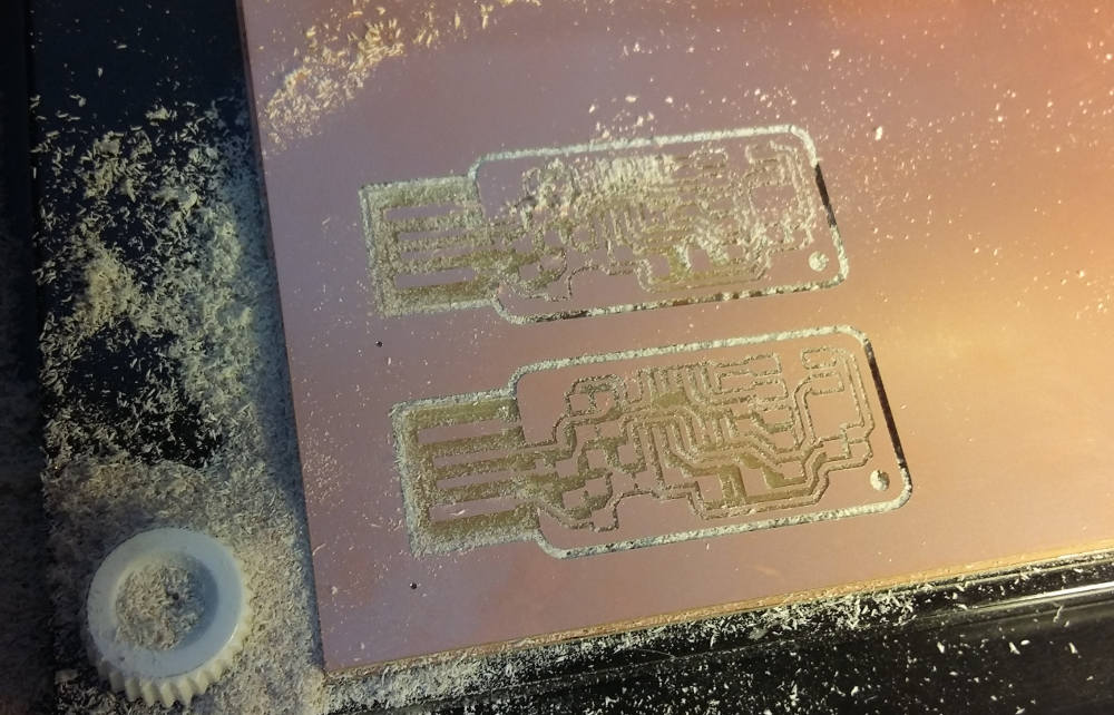
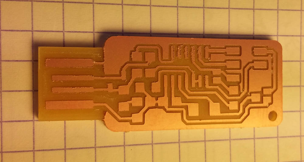
Final result before removing PCB from the machine.
The PCB is too thin to stay inside a USB female connector so we had to add some additional material on the back of the board.
Before starting soldering I washed the board with water and soap.
A nice support and good hints to start comes from
MightyOhm Comics
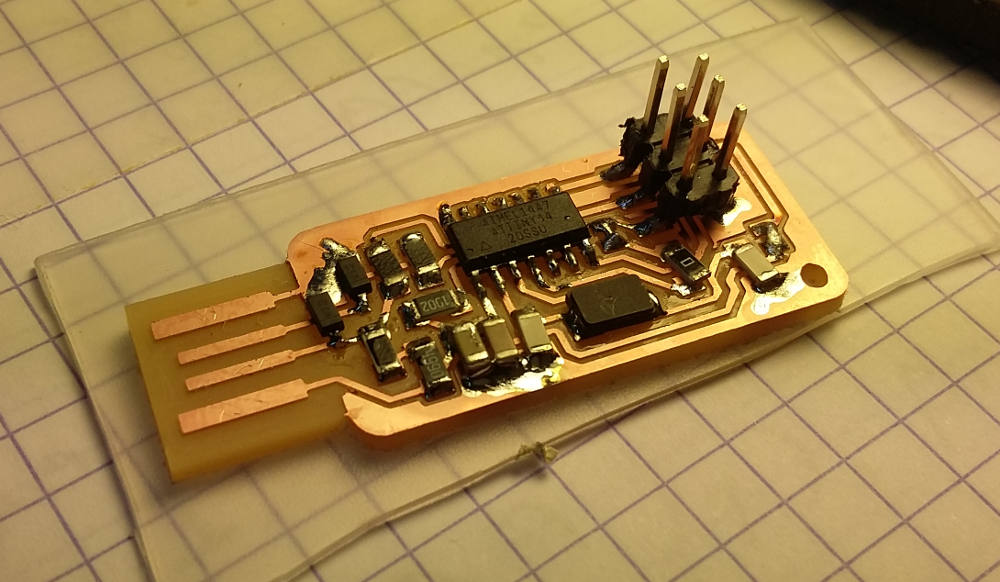
Before soldering I took all components and I glued them to a piece of paper with a strip of tape. Here came my biggest mistake of this class: I took 49k Ohm resistors instead of 49 Ohm. My mistake was also due to the fact that we had not in the inventory 49Ohm resistors, so we used 100Ohm resistors. I took connector pins from another unused board.

Soldering temperature was 370°C. I checked all components from short circuits before going to the next, this made me a little bit slow in the beginning but saved me some debugging time.
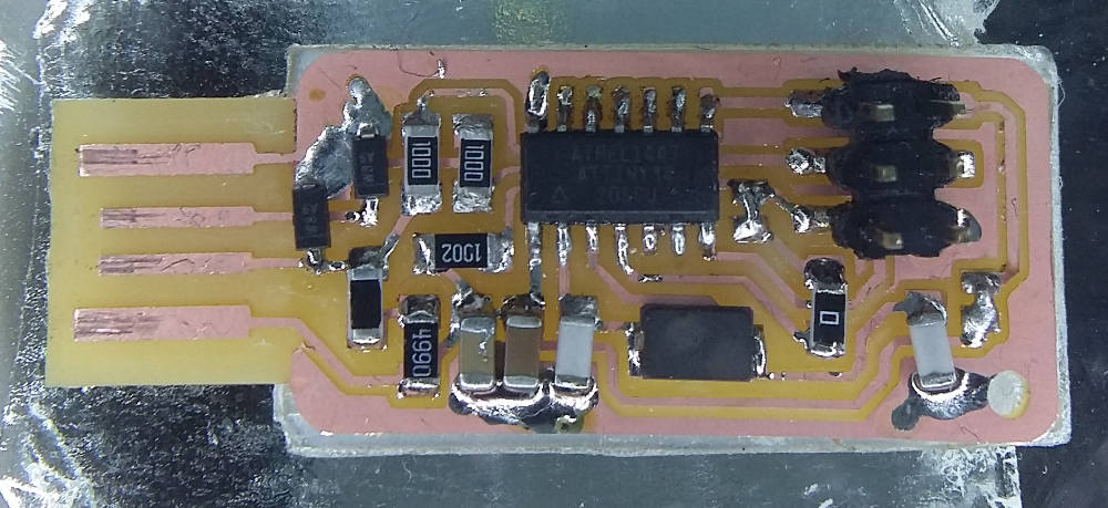
This is a picture of a fixed board with many cable connections since in that board ground poor was missing.

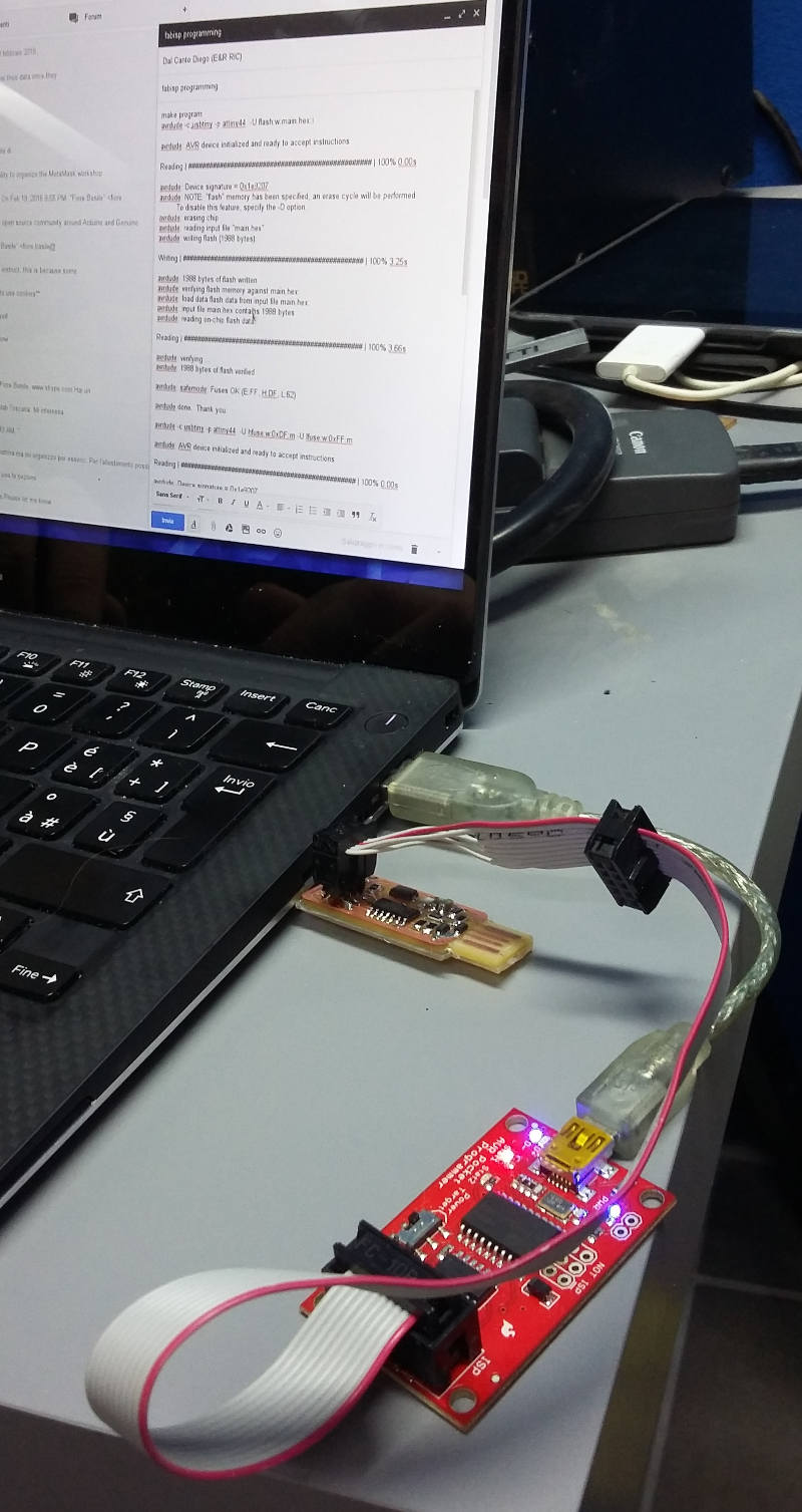
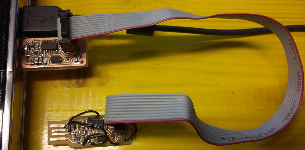
Finally I programmed my board using a programmer connected to the SPI port.
To program the board I needed to install some packages related to AVR programming:
sudo apt-get update
sudo apt-get upgrade all
sudo apt-get install gcc-avr binutils-avr gdb-avr avr-libc avrdude
To see all the tools installed type “avr-” in the terminal and press tab twice (do not hit enter).
I downloaded the
firmware
and changed the makefile to fit on my target board:
Then I set the path to the folder where I have the “Makefile.m” and main.c
 # Name: Makefile
 # Project: custom-class example
 # Author: Christian Starkjohann
 # Creation Date: 2008-04-07
 # Tabsize: 4
 # Copyright: (c) 2008 by OBJECTIVE DEVELOPMENT Software GmbH
 # License: GNU GPL v2 (see License.txt), GNU GPL v3 or proprietary (CommercialLicense.txt)
 # This Revision: $Id: Makefile 692 2008-11-07 15:07:40Z cs $

DEVICE  = attiny44
 #F_CPU   = 12000000    # edit this line for crystal speed, in Hz
F_CPU   = 20000000  # edit this line for crystal speed, in Hz
FUSE_L  = 0xFF
FUSE_H  = 0xDF
AVRDUDE = avrdude -c usbtiny -p $(DEVICE) # edit this line for your programmer
 #AVRDUDE = avrdude -c avrisp2 -P usb -p $(DEVICE) # edit this line for your programmer

CFLAGS  = -Iusbdrv -I. -DDEBUG_LEVEL=0
OBJECTS = usbdrv/usbdrv.o usbdrv/usbdrvasm.o usbdrv/oddebug.o main.o

COMPILE = avr-gcc -Wall -Os -DF_CPU=$(F_CPU) $(CFLAGS) -mmcu=$(DEVICE)
Finally it was time to run the “make” command.
make clean
make hex
make program

avrdude -c usbtiny -p attiny44  -U flash:w:main.hex:i

avrdude: AVR device initialized and ready to accept instructions

Reading | ################################################## | 100% 0.00s

avrdude: Device signature = 0x1e9207
avrdude: NOTE: "flash" memory has been specified, an erase cycle will be performed
         To disable this feature, specify the -D option.
avrdude: erasing chip
avrdude: reading input file "main.hex"
avrdude: writing flash (1988 bytes):

Writing | ################################################## | 100% 3.25s

avrdude: 1988 bytes of flash written
avrdude: verifying flash memory against main.hex:
avrdude: load data flash data from input file main.hex:
avrdude: input file main.hex contains 1988 bytes
avrdude: reading on-chip flash data:

Reading | ################################################## | 100% 3.66s

avrdude: verifying ...
avrdude: 1988 bytes of flash verified

avrdude: safemode: Fuses OK (E:FF, H:DF, L:62)

avrdude done.  Thank you.

avrdude -c usbtiny -p attiny44  -U hfuse:w:0xDF:m -U lfuse:w:0xFF:m

avrdude: AVR device initialized and ready to accept instructions

Reading | ################################################## | 100% 0.00s

avrdude: Device signature = 0x1e9207
avrdude: reading input file "0xDF"
avrdude: writing hfuse (1 bytes):

Writing | ################################################## | 100% 0.00s

avrdude: 1 bytes of hfuse written
avrdude: verifying hfuse memory against 0xDF:
avrdude: load data hfuse data from input file 0xDF:
avrdude: input file 0xDF contains 1 bytes
avrdude: reading on-chip hfuse data:

Reading | ################################################## | 100% 0.00s

avrdude: verifying ...
avrdude: 1 bytes of hfuse verified
avrdude: reading input file "0xFF"
avrdude: writing lfuse (1 bytes):

Writing | ################################################## | 100% 0.00s

avrdude: 1 bytes of lfuse written
avrdude: verifying lfuse memory against 0xFF:
avrdude: load data lfuse data from input file 0xFF:
avrdude: input file 0xFF contains 1 bytes
avrdude: reading on-chip lfuse data:

Reading | ################################################## | 100% 0.00s

avrdude: verifying ...
avrdude: 1 bytes of lfuse verified

avrdude: safemode: Fuses OK (E:FF, H:DF, L:FF)

avrdude done.  Thank you.
One important remark: do not “fuse” twice a board, it will brick it. The Program command do also “fuse” so una “make flash” if willing to flash a board which has already been flashed.
Then to test if the board works, put it in a USB port and type: “lsusb”.