Table of Content
Develop a construction kit using parametric design. Joints have to be reversible.
I used Inkscape to prepare .png files for the vinyl cut. The image have be be B&W, preferable a vector image with smooth profiles. A search of “silhouette” on Google images provides a vast choice of B&W shapes. If the contour of the shape is not perfect (.jpg or other compression) it is possible to fix the image with “Color->Posterize” in GIMP. Can also increment the “Threshold” parameter in “process” Tab in
fab module
to some pixels, this will smooth the shape. It is very important to consider the resolution of the machine, our was 1200 dpi, so we had to export our design with a resolution of at least 1000 dpi. With low resolution images the machine will “print” also pixels.
After Posterizing this image, its size decreased from 1.6 MB to 130 kB:
We left default settings for our Roland vinyl cutter (.camm) in fab module except for force (70 instead of 45) and threshold (2instead of 1). I had some trouble uploading a .png file with transparent background since fab module wasn’t able to open it and I got stuck before I tried with another file with white background.
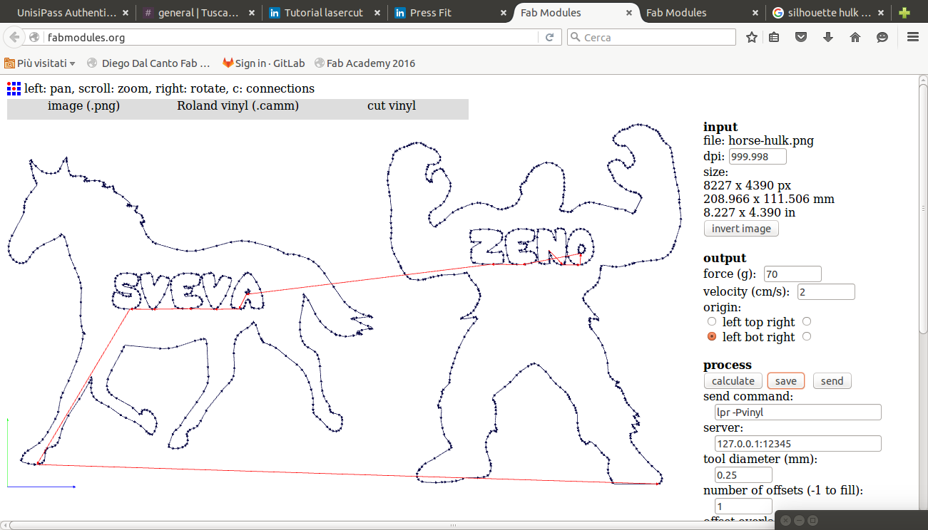
After the process is complete, the result file can be saved and sent to the machine. The file is just a list of commands of “Pen Up” or “Pen Down” with XY coordinates. See here an extract:
PU6570,2878;
PD6570,2878;
PD6570,2878;
PD6570,2878;
PD6570,2878;
PU6570,2878;
The machine reads exactly these commands, so we can just send the file to the USB port without any driver:
$ ls /dev/usb/
lp0
$ sudo su
root@diegoHP:/home/diego# cat path4264-2.camm > /dev/usb/lp0
Can set manually the origin moving the knife with the arrows on the machine and the pressing “Origin”. This is useful to improve the usage of vinyl.
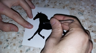
With small pincers I carefully removed extra vinyl from the vinyl sheet.
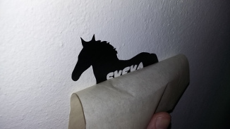
Then using a transfer sheet I finally glued the result to a wall.
Ponoko
is a useful resource for laser cutting, also many tutorial are available there (Ponoko is used also by
Vectorealism
).
Also
Boxmaker
is a very handy resource since it provides .pdf drawing of a box given its outbound dimensions.
123d make
is a very easy to use tool to make construction set out of a design. Can be downloaded for iPad.
FabLab Torino made a very clear and useful
presentation
about laser cutting (Italian).
First I sketched a 3D model with Rhino, I exported .STL files and uploaded to
SketchFab
.
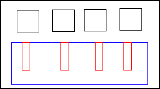
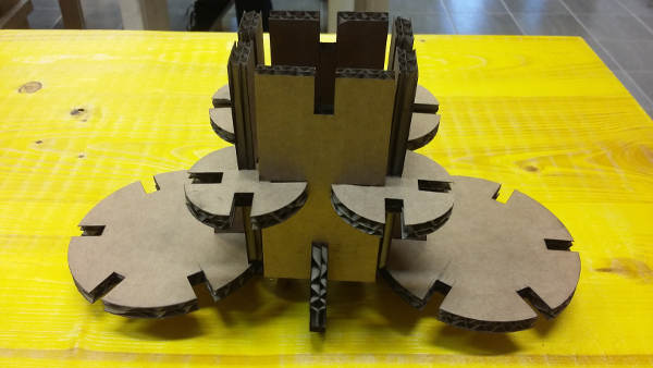
Components of the construction set:
Assembly example:
Fab module
on git lab can translate many input format to many output machine. It enable the addition of an offset to the design to take into account of kerf (not all drivers do). The workflow is made out of input choice->output choice->process parameter->export.
The laser can modulate the intensity with greyscale or coloured source files (cut or engrave). CO2 laser reach an accuracy of 10 micronwhen fiber lasers goes up to 1 micron (good for circuit).
Regarding the kerf and how to measure and handle it I found useful resources in the Fab Academy
Tutorial
:
For a parametric modeling of the press-fit construction kit first I tried Inkscape but I didn’t like it since there it is hard to be accurate, so I decided to try Grasshopper whic have been a good choice in the end since my geometry is easily described with mathematical functions. Also I liked the programming interface which is like Labview, a software which I am comfortable with.
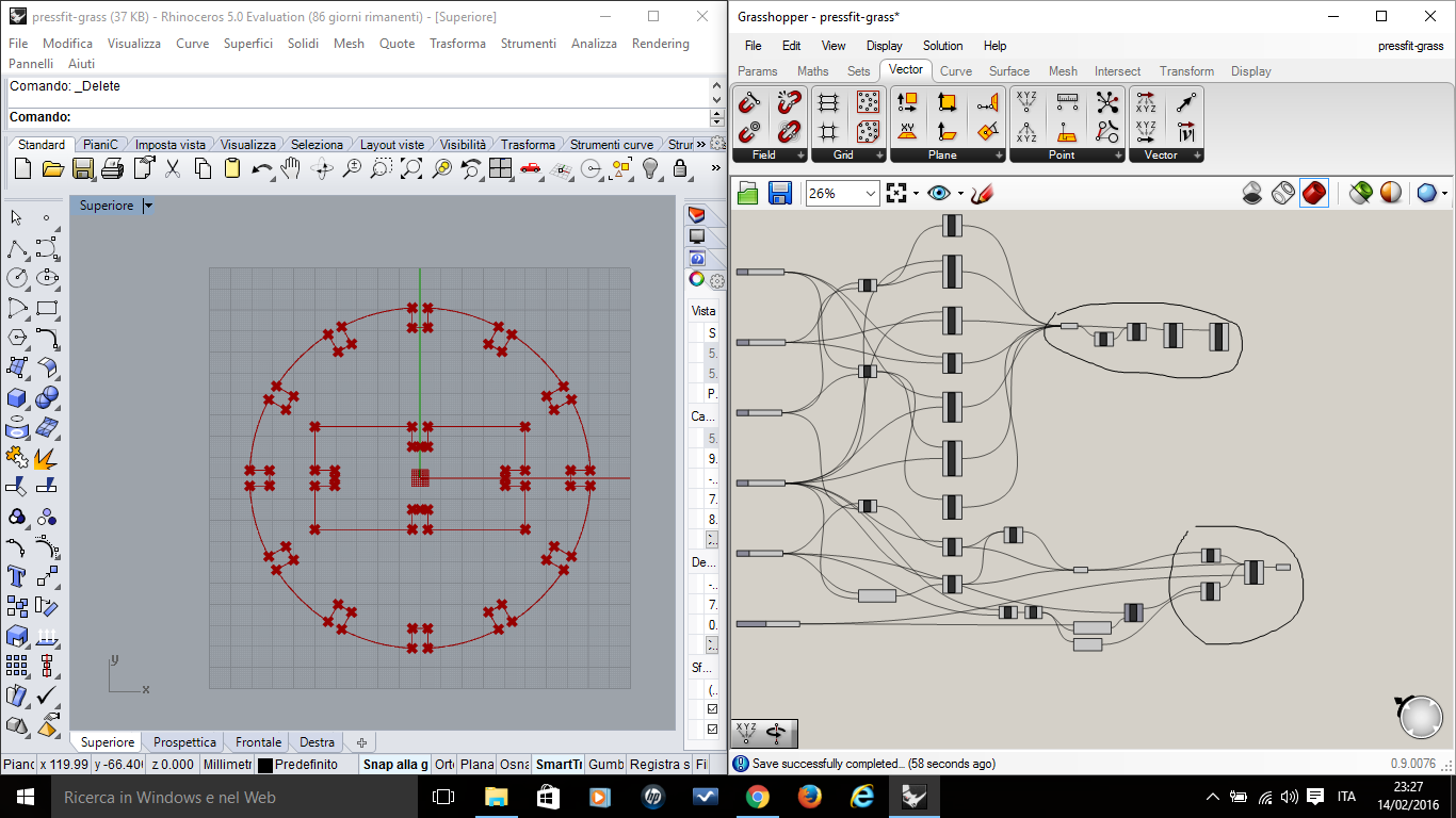
I exported the geometry grom Grasshopper to Rhino with “bake” function (right click in Grasshopper on Geometry). Then I looked for duplicates and I deleted them. I created a closed line and finally I exported to .dxf (unfortunately Rhino .pdf export is not precise). I opened .dxf resulting file in inkscape, added a frame with a different color, set the line to 0,001 mm and in the end print to .pdf. This was also tricky since Inkscape has a bug with .pdf export of curves thinner tha 0.018 mm (which are not displayed). Print instead works correctly.
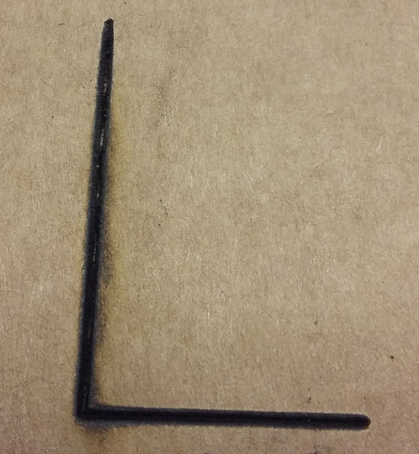
It is important to open the notch a little angle to make easier to put joint toghether. The joint works compressing material.
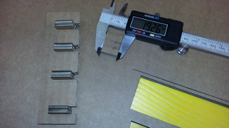
I made many holes and I measured all of them in order to calculate kerf size:
Cardboard_size: 7.23 mm. Line_size 0.01 mm (2 laser passages)
Size_of_squares: 19,68 19,74 19,51 19,84 19,87 19,77 19,21 -> d=19,66 mm
Size_of_holes: 20,12 20,25 20,21 20,15 20,24 20,34 -> D=20,22 mm
Kerf = (D-d)/2= 0,28 mm
Notch size= 7,23 mm (7,23 from design -> 7,50 measured)
Best_fit: 6,93 mm (7,25 measured)
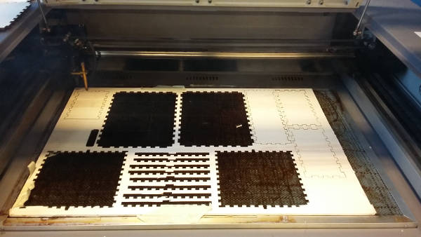
Since we had never cutted 7mm cardboard with this Laser Machine, I had to make some test in order to find correct cutting settings (cardboard is a little tricky to cut since it can get fire…).
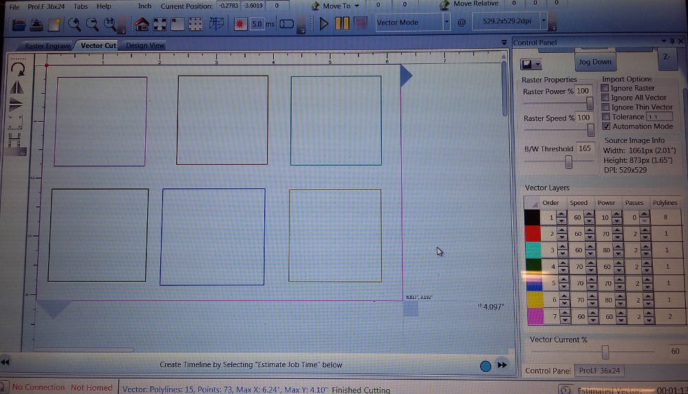
I made with Inkscape a series of squares of different colours (line 0,01) to test Laser cut with different Speed/Power combination.
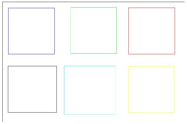
I assigned for each colour a different combination of Speed/Power. Vector Current was the same for all.
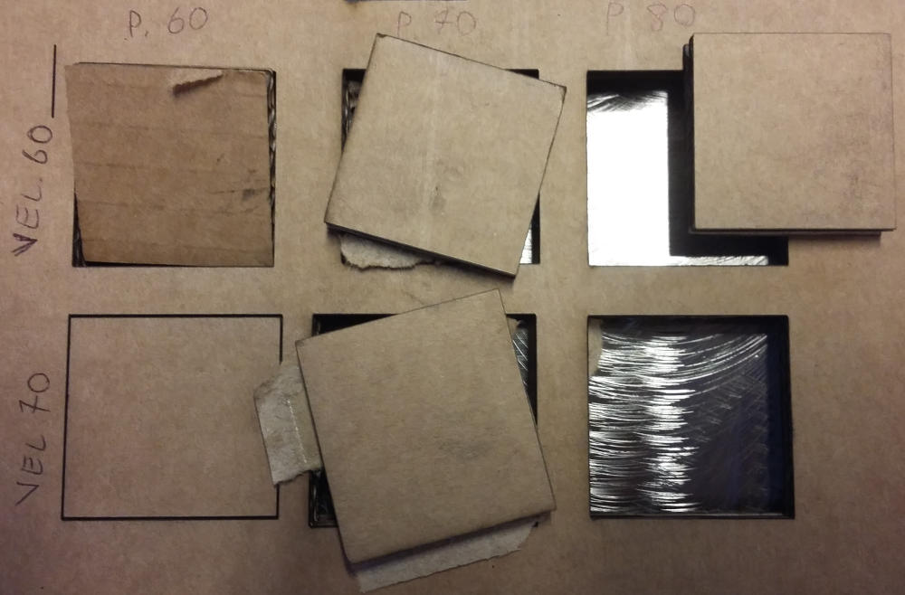
After a first run I realised that only one passage was not enough and too much power could fire the cardboard, so I decided to go for 2 passages: best combination for my point of view is Speed 60 and Power 80 at 60% Vector Current.
I made the mistake of running a job before doing the focus. Laser Power wasn’t high, but the cardboard started to make smoke so I stopped the job immediately, then I realised about the focus (I had moved the “Z” for an inspection.
Finally I cut few pieces with different sizes from a piece of cardboard:
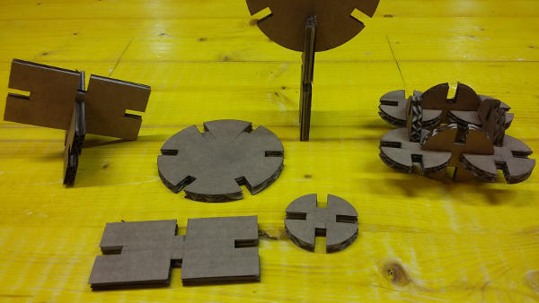
Then I played with my personal “LEGO” bricks:
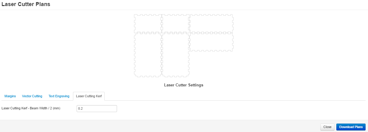
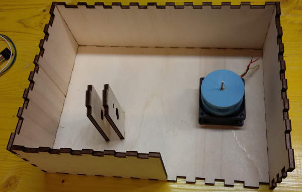
With MakerCase I made a case for my final project assembly.
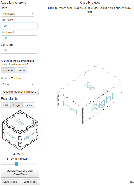
Makercase is a very useful and handy tool. It requires the dimensions of your box, joint type, material width, kerf (half of the laser beam):
Luckly I found a piece of wood with enough space for my design. That piece of plywood was 5.86 mm instead 6 mm I tought “by default” and this ended to be a little mismatch in joints. I was able to cut the wood with only one pass, 50% speed, 100% power, 100% vector current. The laser cut machine had been calibrated recently so it was very efficient.
Top vision of my Box:
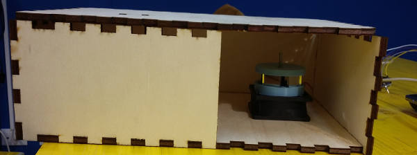
Front vision:
Box notches (0.28 kerf):
After calibration, laser kerf reduced to 0.17 mm. Notches size:
20.05;20.20 => 20.12 mm
Kerf calculation:
(20.12-19.8)/2=0.32/2 = 0.17 mm
bar_illustrator.pdf
caseplans.3dm
circle_illustrator4.pdf
pressfit-grass.3dm