Computer-Controlled Machining
Overview
Last updated: 16/03/2016
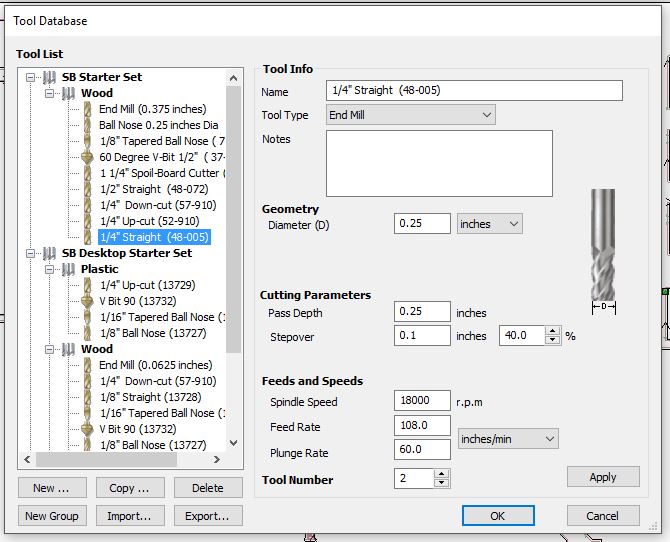
Objective Make something big (on a CNC machine). Learning outcomes Document the process of design and production to demonstrate correct workflows and identify areas for improvement if needed; Have I... Explained how I made my files for machining (2D or 3D)? Shown how I made something BIG (setting up the machine, using fixings, testing joints, adjusting feeds and speeds, depth of cut etc)? Explained problems and how I fixed them? Included original design files (Eagle, KiCad, Inkscape, .cad - whatever)? Summary The assignment was literally defined as "make something bigger than a chair". Out of necessity, I decided to build a table to be put nearby the milling machine here in Siena. I used both Rhino and Illustrator for the drawings, as well as VCurve for preparing the .camm files to send to the Shopbot.Introduction on the Shopbot In Siena we have the Shopbot model PRSalpha 96-60 which is a cute yet scary machine to me. The machine has: 1.step resolution .0006” 2.positional accuracy of +/- .002” It came together with both end mills and straight cuts drill bits, even though for this week we only used a 1/4" straight cut bit. In order to operate the machine, three definitions need to be clear, as I found nicely explained here: 1.Spindle speed: varies from 0rpm to the maximum mechanically allowed by the motor. In our case it varies from 0 to 18 000 rpm; 2.Feed rate: speed at which the spindle itself moves around. It needs to be optimised so that nor the material or the tool heat up too much. 3.Chip load: it is the amount of wood that one cutting edge of the tool can remove; These parameters are linked by the following equation and they are always dependent on both the drill bit and the material that are used. Chip Load = feed rate ( ipm ) ÷ ( cutting rpm x number of cutting edges )Since we used Shopbot bits, we found the specifics here.
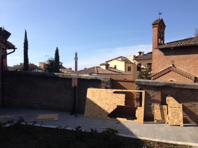
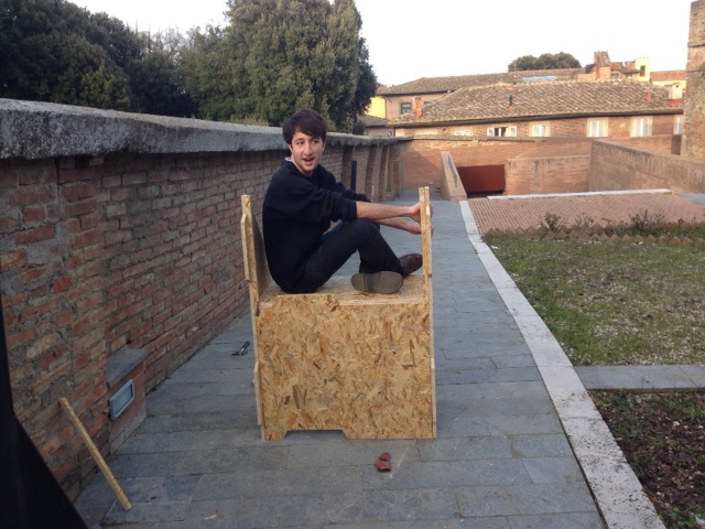
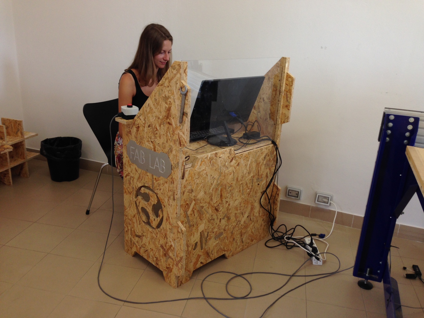
Concept Many interesting and inspirational works done with the CNC router can be found at OpenDesk and at atFab. For this assignment I wanted to design a desk that could be placed nearby the Shopbot to accommodate a desktop, in place of what you see below-left. On the right, instead, I show off the cool location of our wood-workshop, from where you can see the Mangia tower!

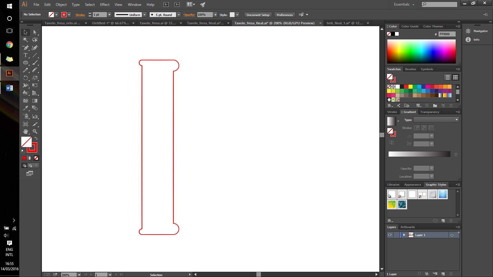
2D Modeling From the 3D sketch I mainly followed this tutorial to actually figure out the best ways to export the model to Illustrator to do the finishes. From each one of the viewpoints I did launch the command "Make2D" and I picked: Drawing layout: current view; Options: show hidden lines; The result was sufficient for what I needed to do. However, the geometries were here and there open, as I later figured out when I opened VCurve. With Illustrator I first of all set the size of the canvas to 1200x2300mm, so that I could figure out if all my drawings could fit. Secondly, I started to make some pressfit junctions that would have taken me too long with Rhinoceros. After I had done that, I also made dog bones for the internal cuts. The picture below shows how I did them and shows the difference in sizes which relates to the dimension of the drill bit. The one on the left is the dog bone for 1/8" drill bits, while the one on the right is for 1/4" drill bits. [2]
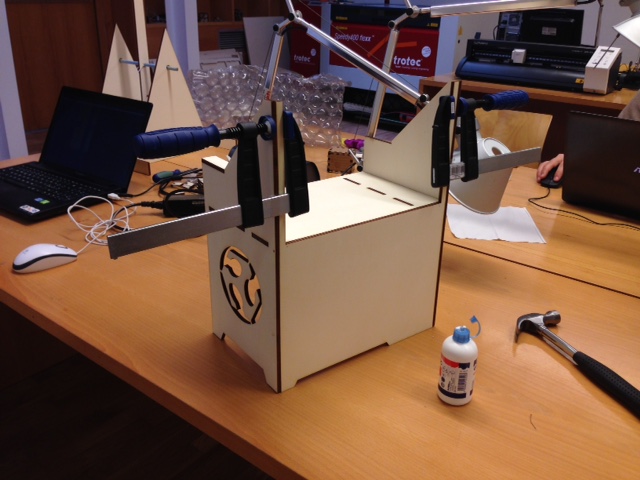
Prototyping It was then that I built a prototype to actually try the fittings and see if I could build it later. For prototyping I used 6mm thick plywood and the lasercutter. Since the final prototype would have been made out of 18mm thick wood, I scaled everything down of 1/3.

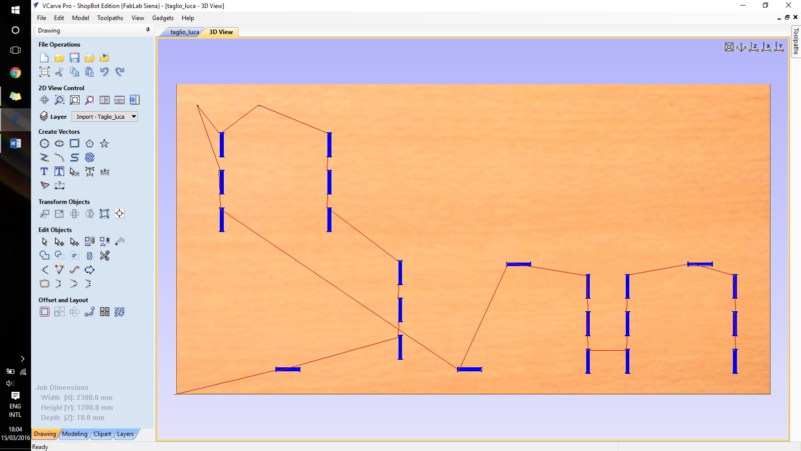
VCarve It follows the process that I followed in VCarve, which in short includes drilling 6 holes for stability of the plank, drilling the pockets and finally the outlines [3]: 1.Generate new file with canvas size and thickness. In our case the canvas size was of 1200x2400mm for 18mm thickness; 2.Position the illustrator files in the canvas, making sure that the space in between each object exceeds the size of the drill bit. Unfortunately, I could not fit all of my pieces and I had to ask Matteo to exchange some of his space with some of mine. 3.Select the drill bit size, the speed and the feed rate. As explained in the introduction, that was calculated with the formula Chip Load = feed rate ( ipm ) ÷ ( cutting rpm x number of cutting edges );
 4.Select the drill holes and make drill path.
 5.Select the inner profiles and make pockets;
 6.Select the outer profiles and make outlines.
 I got an error at this point, meaning that the software did not recognise my objects as closed geometries. I had to go back to illustrator and for each path select everything and to "join". After that things worked out properly.
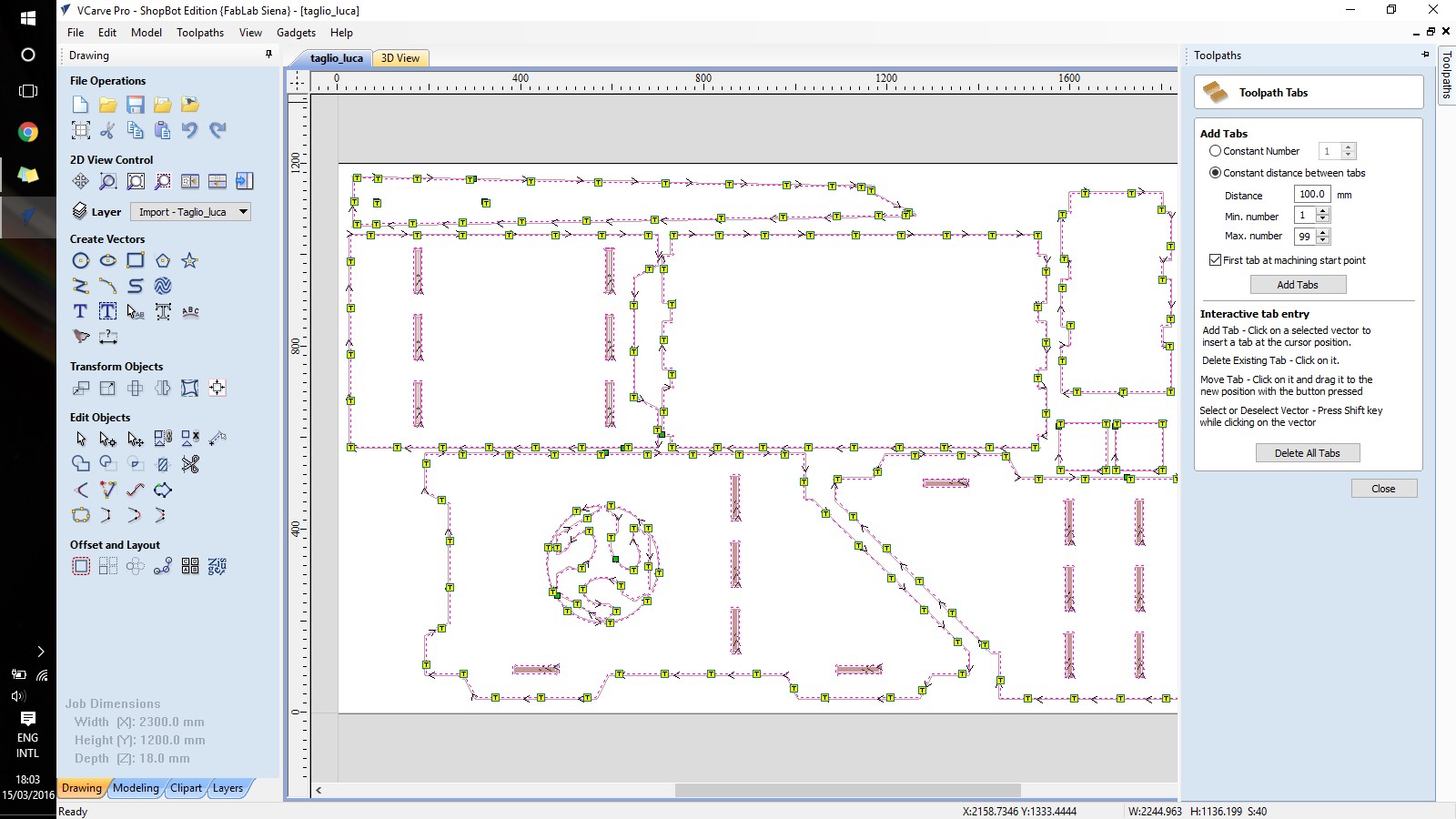
 7.Add the tabs;
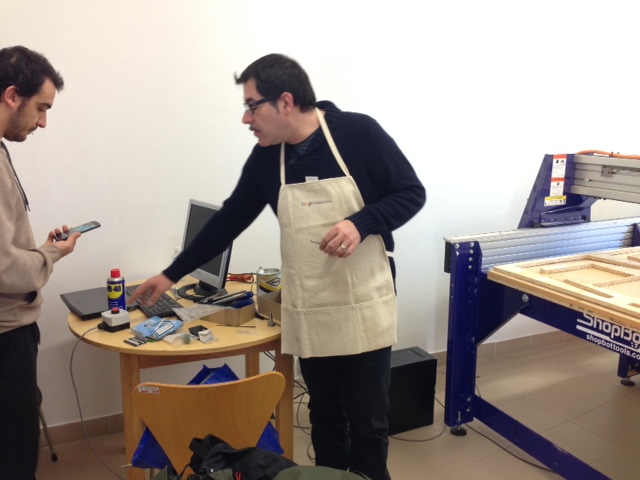
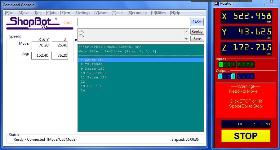
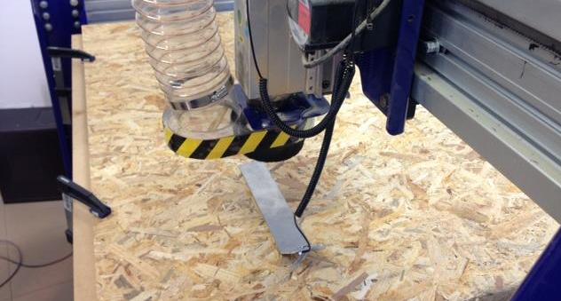
Cutting Operating the machine should happen in a safe way, first of all. It is important to keep in mind that it is better to throw away a plank of wood than your hands ;) It follows the process that I followed: 1.Insert the proper drillbit (1/4 Straight); 2.Open the Shopbot software; 3.Launch the command C5-Spindle Warm Up Routine (left picture); 4.Position the metal plate under the tool and launch the command C2-Zero Z Axis (right picture);


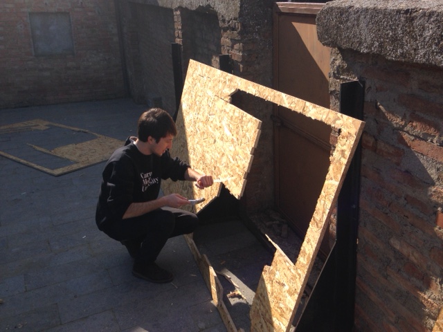
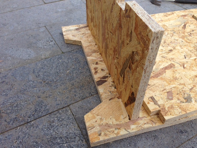
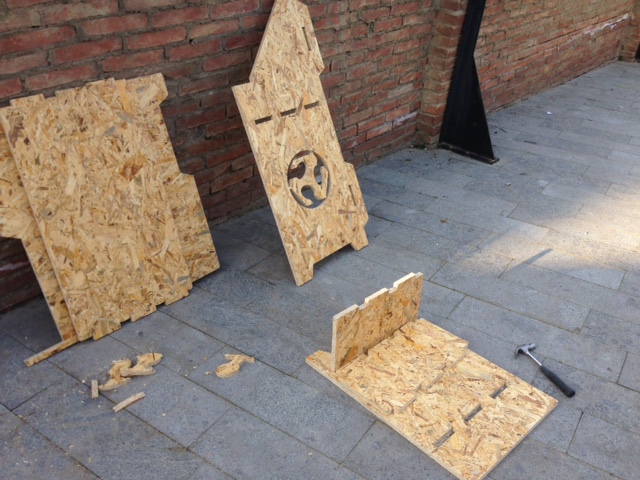
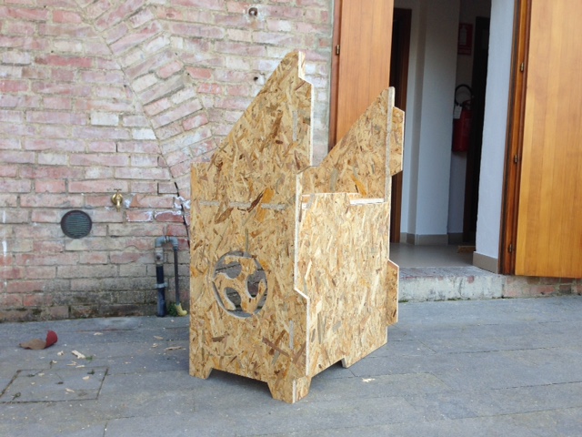
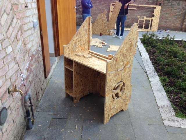
Finishing A lot of sanding happened in order to achieve the final results, which still are quite satisfying as I did not need any glue! I manually removed the tabs with a scalpel and then I started to sand things down. The pressfit pieces, in particular, required to be quite smooth in order to fit as I had 18mm males for 18mm females. I still had to use the hammer here and there.
Conclusions I started with a debated feeling about the assignment. Since I have quite some experience with traditional wood workshops, at first I did not really find it a big advantage to cut objects in 2D with a machine that can do much more. Apart from that, I think that my process went quite linear, with only minor mistakes here and there. Eventually I liked a lot the combination of machine work and manual labour to do the finishes. I think the main advance of CNC milling to respect to using traditional tools comes when you want to make pockets. The jig saw is just a pain in the ass to use. Anything to do differently next time? First, maybe reduce the distance in between each tab, as I had to manually remove quite a lot of them. Secondly, since in some parts it did not really cut through, I would like to start the .camm file from the bottom of the plank to cut, not from above like we did.
Table of Content
Resources
- [1] Rhino Drawing
- [2] Illustrator Drawing
- [3] VCarve file