Project Development
OverviewLast updated: 07/07/2016
Objective Complete your final project. Track and document your progress. Create a final project slide in the archive according to the specifications provided. Learning outcomes 1.Evaluate project plan;2.Apply time management techniques; 3.Summarise and communicate the essence of a project;
Summary This page begins with a quick introduction on my final project EMI. It then explains all the manufacturing processes, from hardware to software.
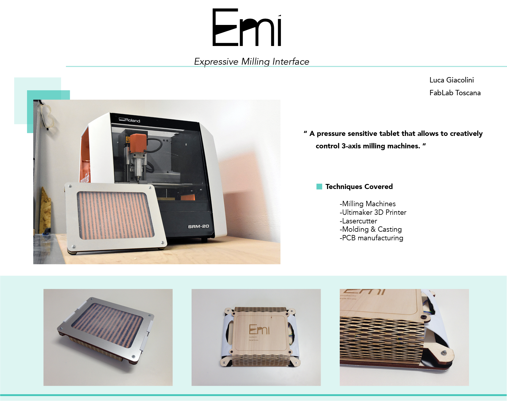
EMI: Expressive Milling Interface Could machines evolve into something more co-creational that gives the maker more of a sense of control?
EMI will allow the artisan to combine the expressivity of hands with CNC routing. It is a touch tablet with pressure sensors that can be used as a controller for the Roland SRM-20. A matrix of 12 x 16 sensors will detect the location and the intensity of the pressure applied and will move the spindle there. The x and y-axes are mapped to the location of the finger on the tablet. The z-axis is mapped to the pressure applied. The spindle would always be spinnning at 12000 rpms and the material to be milled shuld be soft.
 EMI is a prototype and the first step of a much more ambitious project, that is creating an interface for refining digitally manufactured objects.
Building the touchpad When looking around for inspiration I run into the following projects that inspired my research:
1. Wearable Sensor Matrix
2. Plug and Wear basically do what I want to do. 3. Sensor with velostat
4. Arduino unfortunately retired this product;
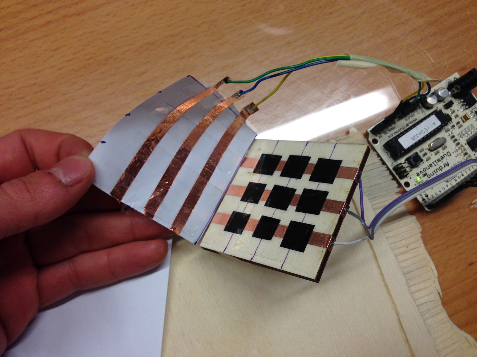
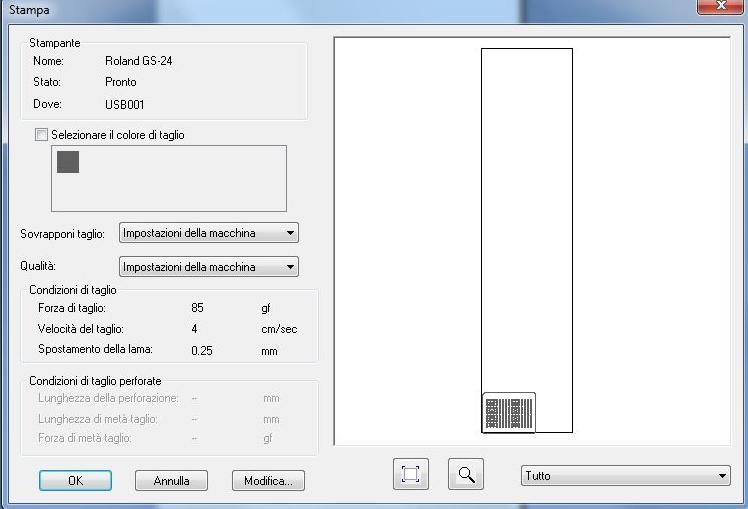
I decided to use Velostat to build my sensors. Velostat is a semiconductor that varies its resistance value when compressed. The first step I made was to build a 3x3 matrix sensor, with 3 rows of copper tape perpendicular to 3 columns. I also cut some vinyl to separate each track, so that I could limit the interfeerence. I red the values with the arduino and I noticed that despite some fluctuation, I could really see which sensor was pressed on the Serial monitor. That motivated me to make a larger one.
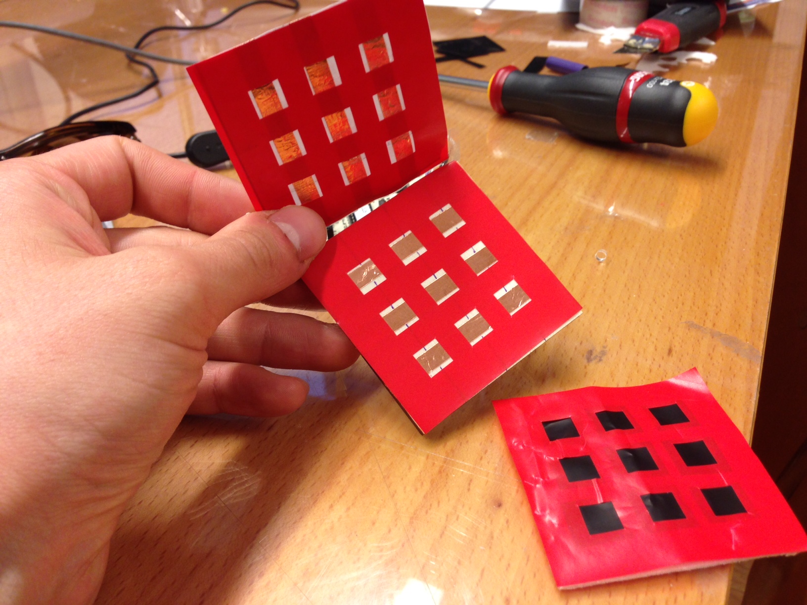


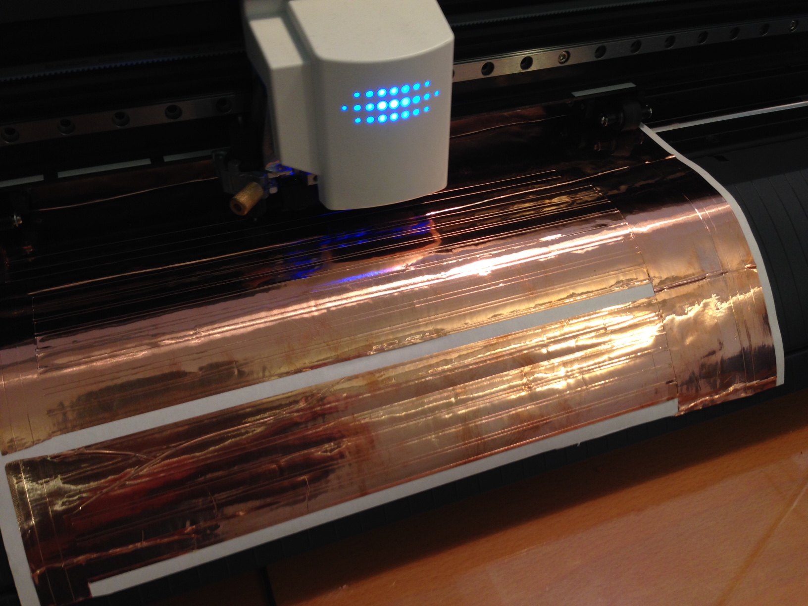

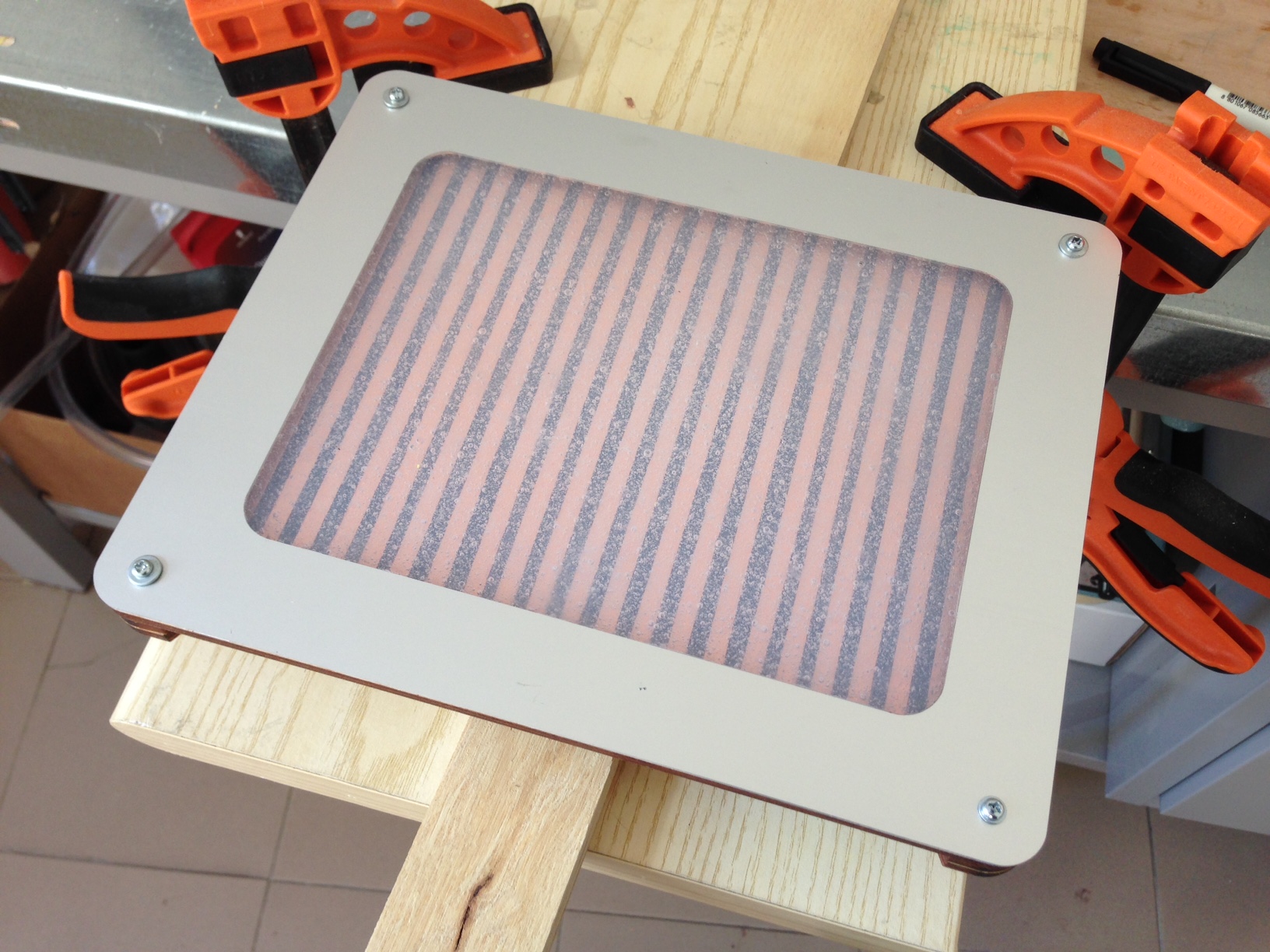
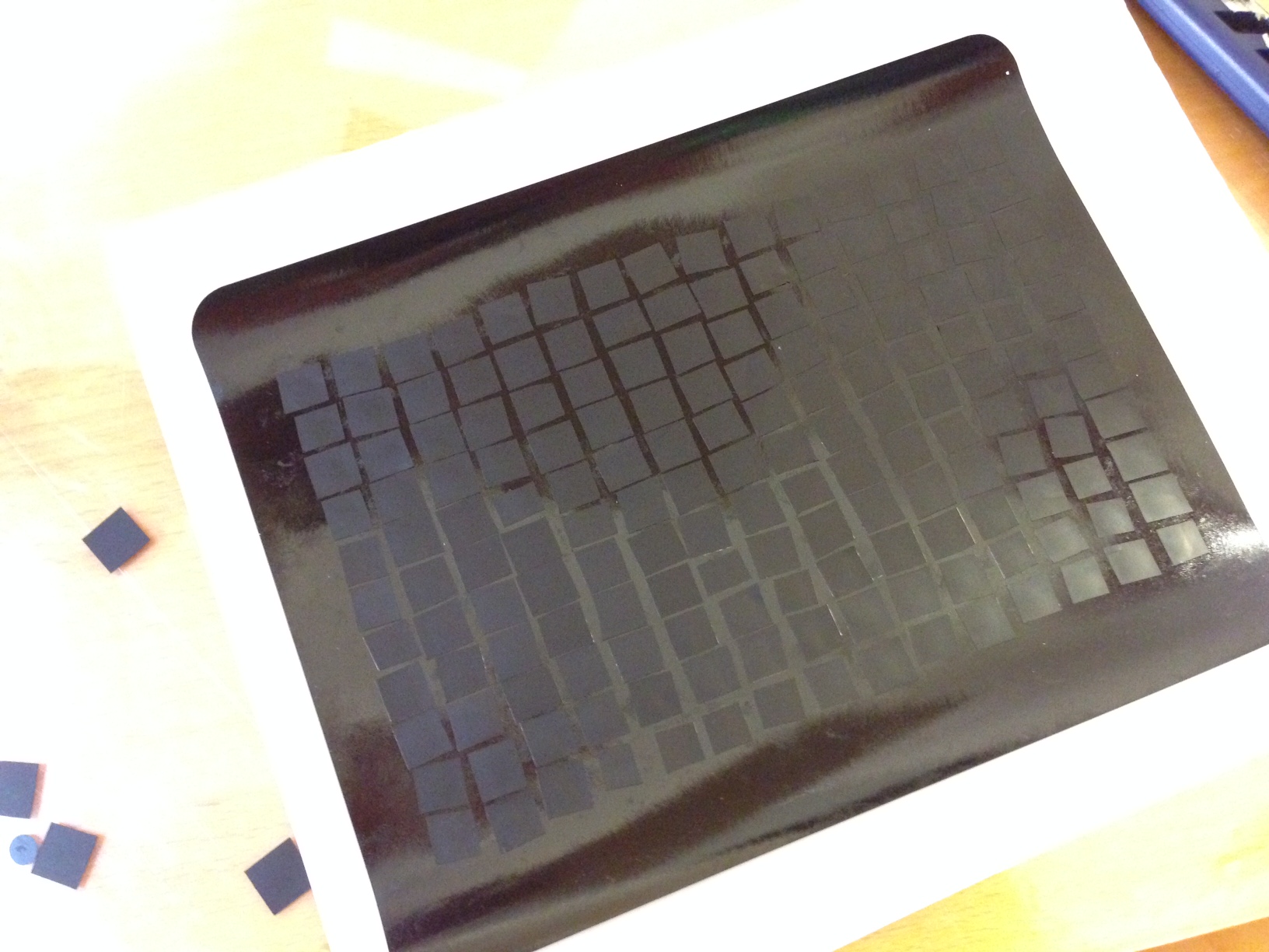
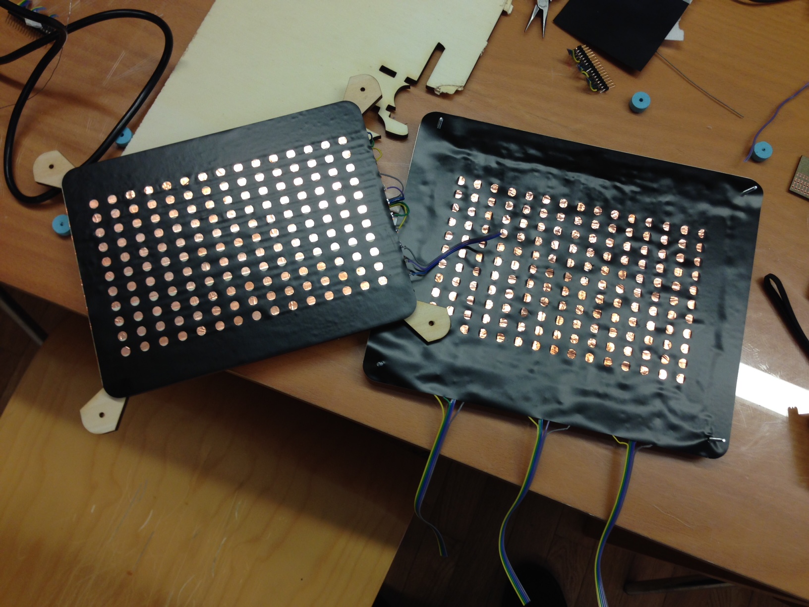 After that I made another vinyl mask and I attached a square of Velostat on top of each circle (11x15). That should reduce the interference between each sensor. Eventually I made a simple mold for spacers, so that the columns and the rows could be somehow in tension yet never completely touching.


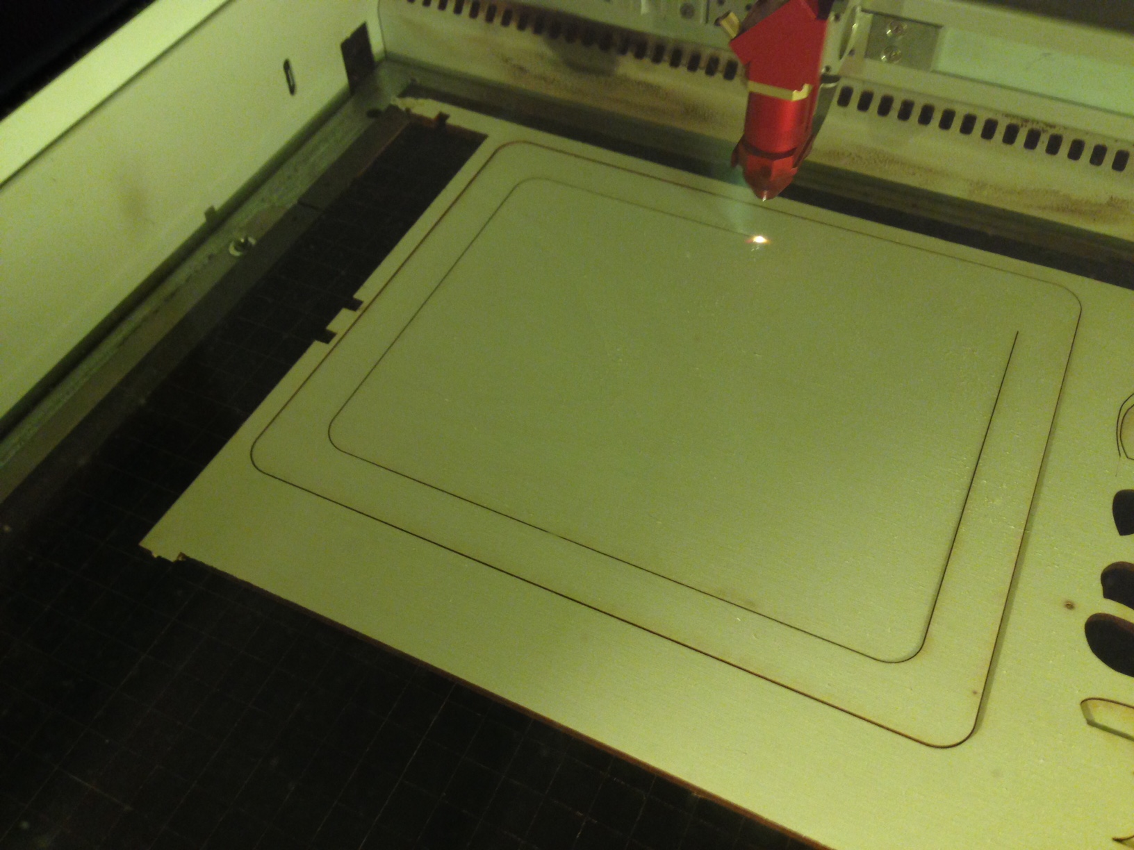
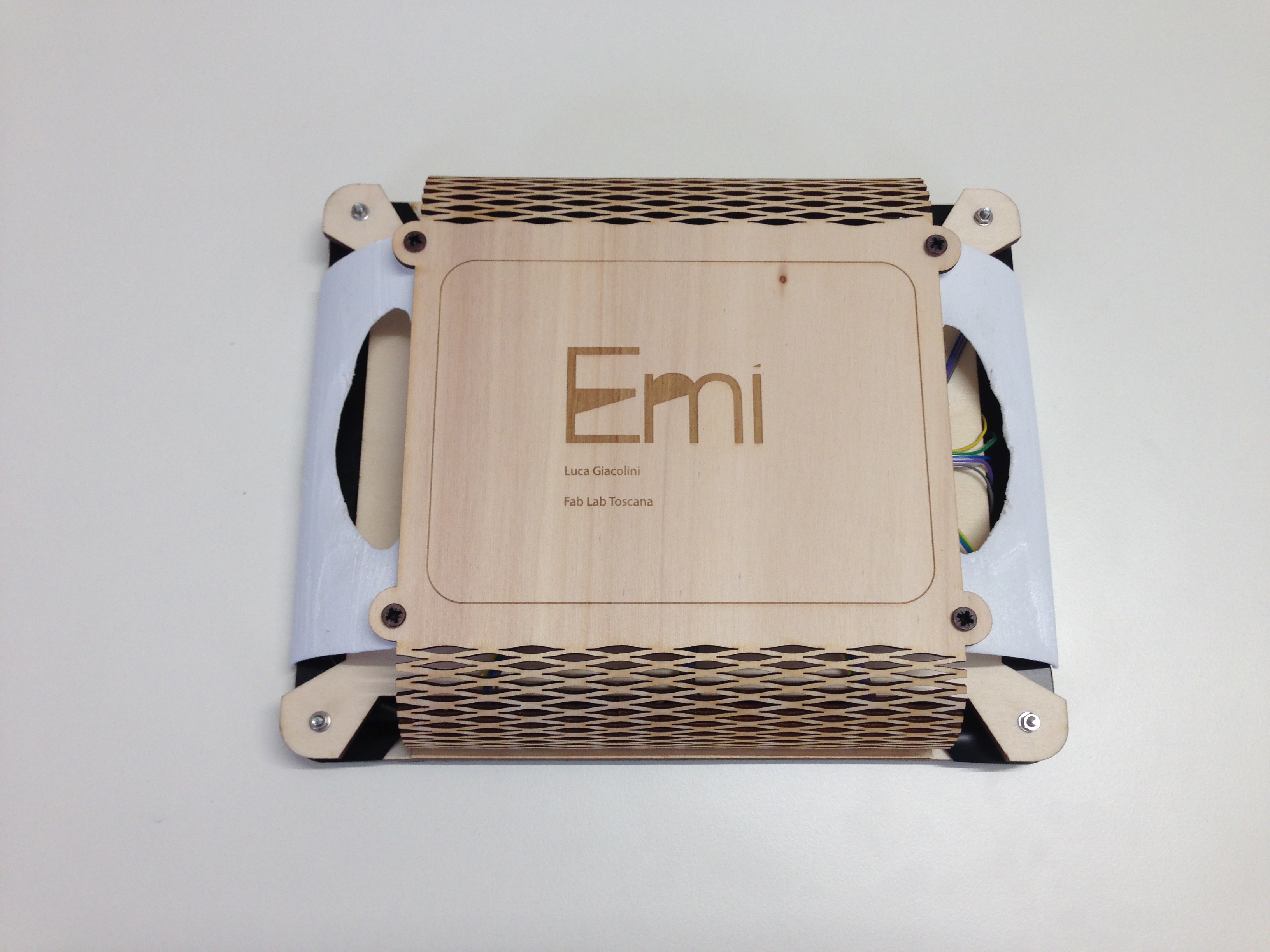
 When it came down to designing the back cover, I wanted to lasercut a pattern on a 3mm plywood board, in order to make it bendable. I downloaded the vectorial pattern from here
 And here is the final design! I am overall quite satisfied with the look, even though it is definitively too bulky.
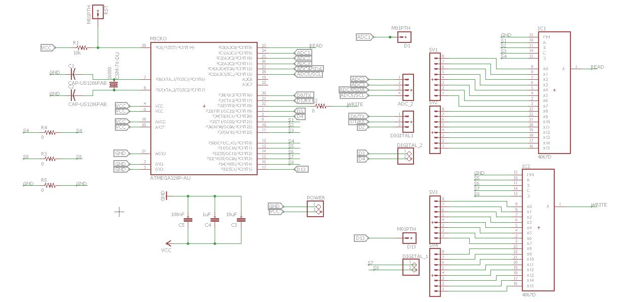
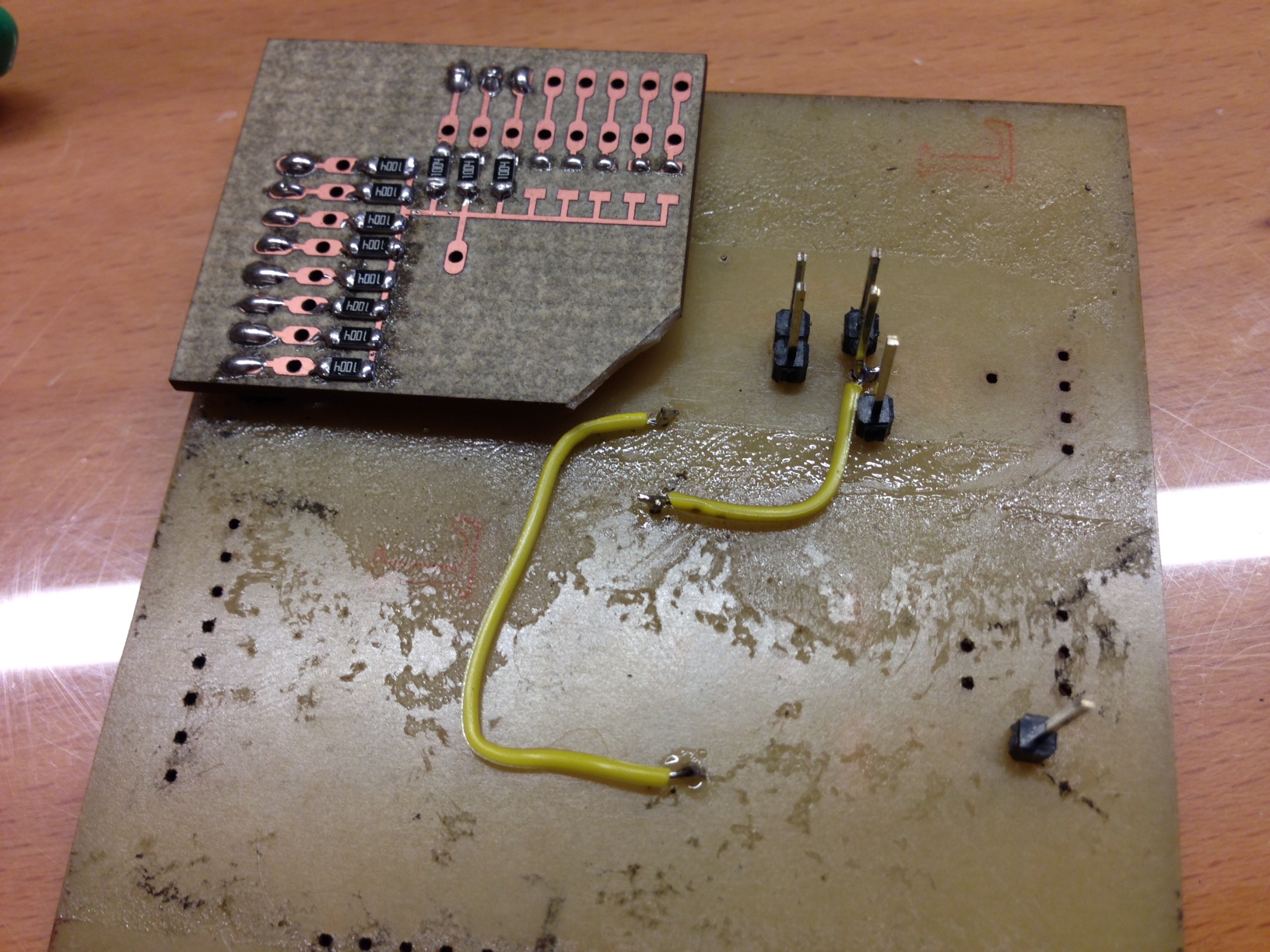
Pressure sensor board After I had made some preliminary tests with the Arduino Mega, I started to think about how to get the same pinout on a self-made board. In fact, I needed 15 analog read inputs and 11 digital write outputs. Taking the advice of my instructor, I implemented two Multiplexer/Demultiplexer on a Satshakit. In particular, I took the Eagle file of the Satshakit Micro that I modified a bit during Week 15. Starting from there, I added two HE4067BT ICs. Despite it was the first time that I used such a component, I quite easily understood their work flow. A multiplexer 1:16 needs 4 digital pins to be controlled in binary, Enable pin attached to GND, the actual signal pin to be multiplexed, Vcc and GND. In designing my board, I wanted to make something that I can perhaps use again in the future. Therefore I did not put the resistors on it in the first place. As shown in the schematic below, I could not bridge two pins, so I attached them later with two jumpers at the back of the board.
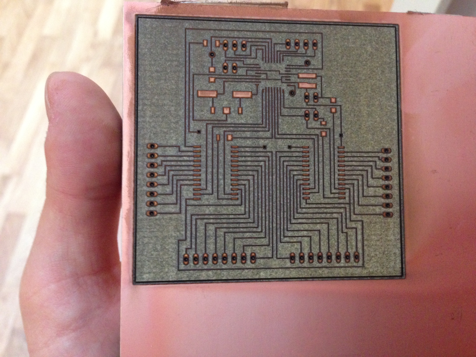
 I lasered the board following the instructions I put in Week4. When soldering, I decided to bring out only the communication pins from the Satshakit: ISP and RXTX Serial.


Board Programming The Satshakit Micro can be flashed with the Arduino IDE. I did it and I compiled, with the great help of Pietro Rustici, the following piece of code. Basically, I get a matrix on the serial monitor where I see which point in the tablet is pressed. I moved from analog reading to digital reading because of the confused data that I was reading at first. Appearently it is not as easy as I thought and it is not scalable from 9 to 156 sensors, as I tried to do.
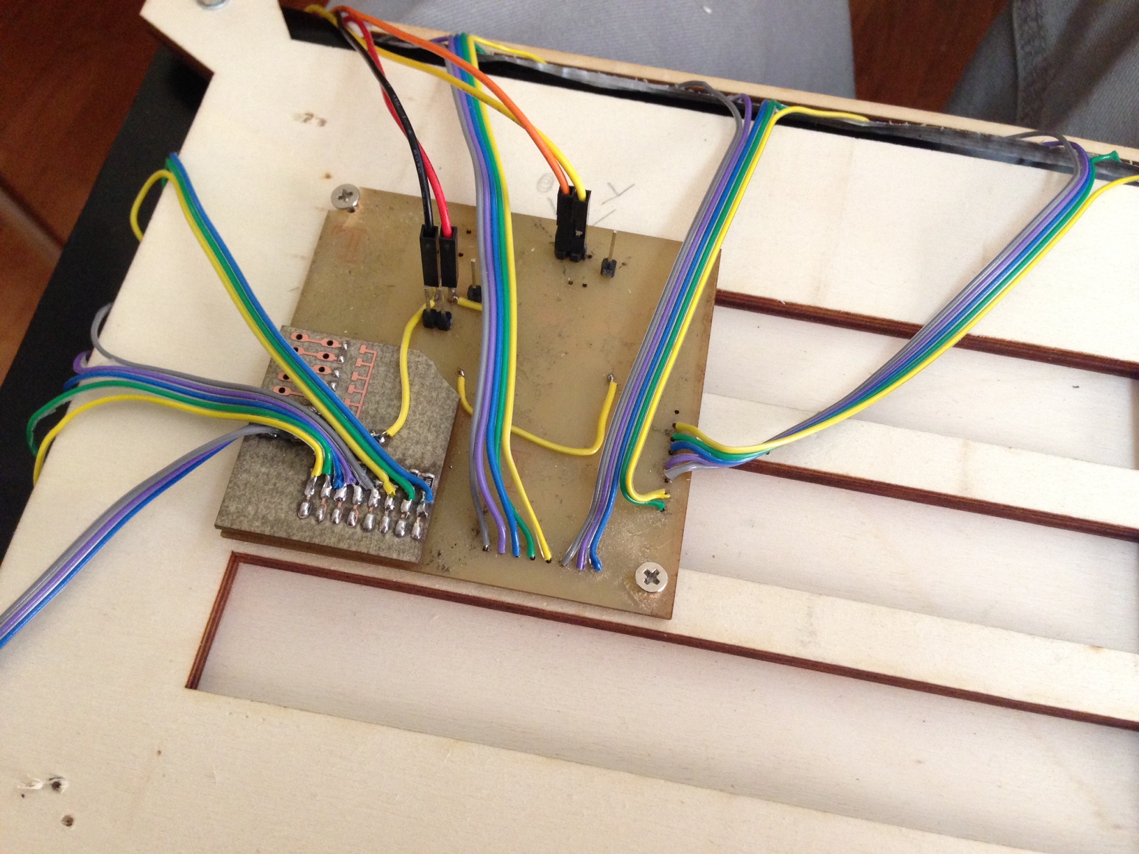
The board needed the ISP programmer in order to be programmed, as shown on the left. I also used the breakout board that I made in week15. The board needed then an FTDI to read from Serial, as shown on the right.

//multi/demultiplexing serial


//    15 analog reading pins
//
//    Z---->A0
//    A0--->D5
//    A1--->D6
//    A2--->D7
//    A3--->D8

//--------------------------------------------------------------------------

//    11 digital writing pins
//    Z---->D2
//    A0--->D9
//    A1--->D10
//    A2--->D11
//    A3--->D13

 int rowread = 4;
 int colread = 15;
 int rowwrite = 4;
 int colwrite = 11;
 unsigned long acttime;
 unsigned long prevtime;
 int val = 0;

  //declaring the matrix for the readings

  bool readings [15][4] = {{0,0,0,0}, {0,0,0,1}, {0,0,1,0}, {0,0,1,1}, {0,1,0,0}, {0,1,0,1}, {0,1,1,1}, {1,0,0,0}, {1,0,0,1}, {1,0,1,0}, {1,0,1,1}, {1,0,1,1}, {1,1,0,0}, {1,1,0,1}, {1,1,1,0}};
  bool writings [11][4] = {{0,0,0,0}, {0,0,0,1}, {0,0,1,0}, {0,0,1,1}, {0,1,0,0}, {0,1,0,1}, {0,1,1,1}, {1,0,0,0}, {1,0,0,1}, {1,0,1,0}, {1,0,1,1}};


void setup() {

  Serial.begin(9600);

}

void loop() {

  //first loop, one loop per row
  for (int i = 0; i < colwrite; i++)
    {
      //selecting the channel on the multiplexer
      digitalWrite(9, writings [i] [1]);
      digitalWrite(10, writings [i] [2]);
      digitalWrite(11, writings [i] [3]);
      digitalWrite(12, writings [i] [4]);

      //pulling the row high
      digitalWrite(2, HIGH);
      prevtime = millis();

      //second loop, one loop per column
      for (int k = 0; k < colread; k++)
        {

          digitalWrite(5, readings [k] [1]);
          digitalWrite(6, readings [k] [2]);
          digitalWrite(7, readings [k] [3]);
          digitalWrite(8, readings [k] [4]);
          val = 0;

          //simple digital filter
          val = analogRead(A0);
          val += analogRead(A0);
          val += analogRead(A0);
          val /= 3;

          //in this example, the output matrix only shows 0 1, according to when a sensor is pressed
          if(val > 0)
            {
              Serial.print("1");
            }
          else
            {
              Serial.print("0");
            }
          Serial.print(" ");

          //pulling the writing pin low again. It might cause some disturbance
          digitalWrite(2, LOW);
          delay(2);

        }

        //printing the matrix
        acttime = millis();
        Serial.print("    ------>   ");
        Serial.print(acttime - prevtime);
        Serial.print("ms");
        Serial.println();
    }
    Serial.println();
    Serial.println();
    Serial.println();
    Serial.println();

}
Below is a videoclip of the interaction with EMI and the Serial Monitor.
I mainly believe that the reason why the result is little stable is electrical, not software. Probably each strip amplifies the signal of the next ones. That is also why I scaled it from analog to digital input.
Controlling the Roland This part was probably the most difficult for me: getting the Roland communicate through an Arduino to my sensor board. First of all, I had a look at what others had done. Hacking a Roland SRM-20 is quite well documented. Three projects mainly inspired my work: 1. This project shows how to hack the spindle with an arduino. 2. Chocolate millin machine is a nice and creative project where a touch screen was attached to the Roland in order to "draw" on chocolate pieces. 3. This project shows an interesting customisation of both the hardware and software of the Roland.
The steps to hack the roland are actually quite linear. The support software onSupport allows you to download the Arduino API manual, with a couple of basic instructions. It is a confidential document, so I will only share here the function list of the API.
 After that, you need to install the drivers for your laptop at this link.
After you remove the back cover, you have to plug in an Arduino as shown in the picture below.
After that, you need to install the drivers for your laptop at this link.
After you remove the back cover, you have to plug in an Arduino as shown in the picture below.
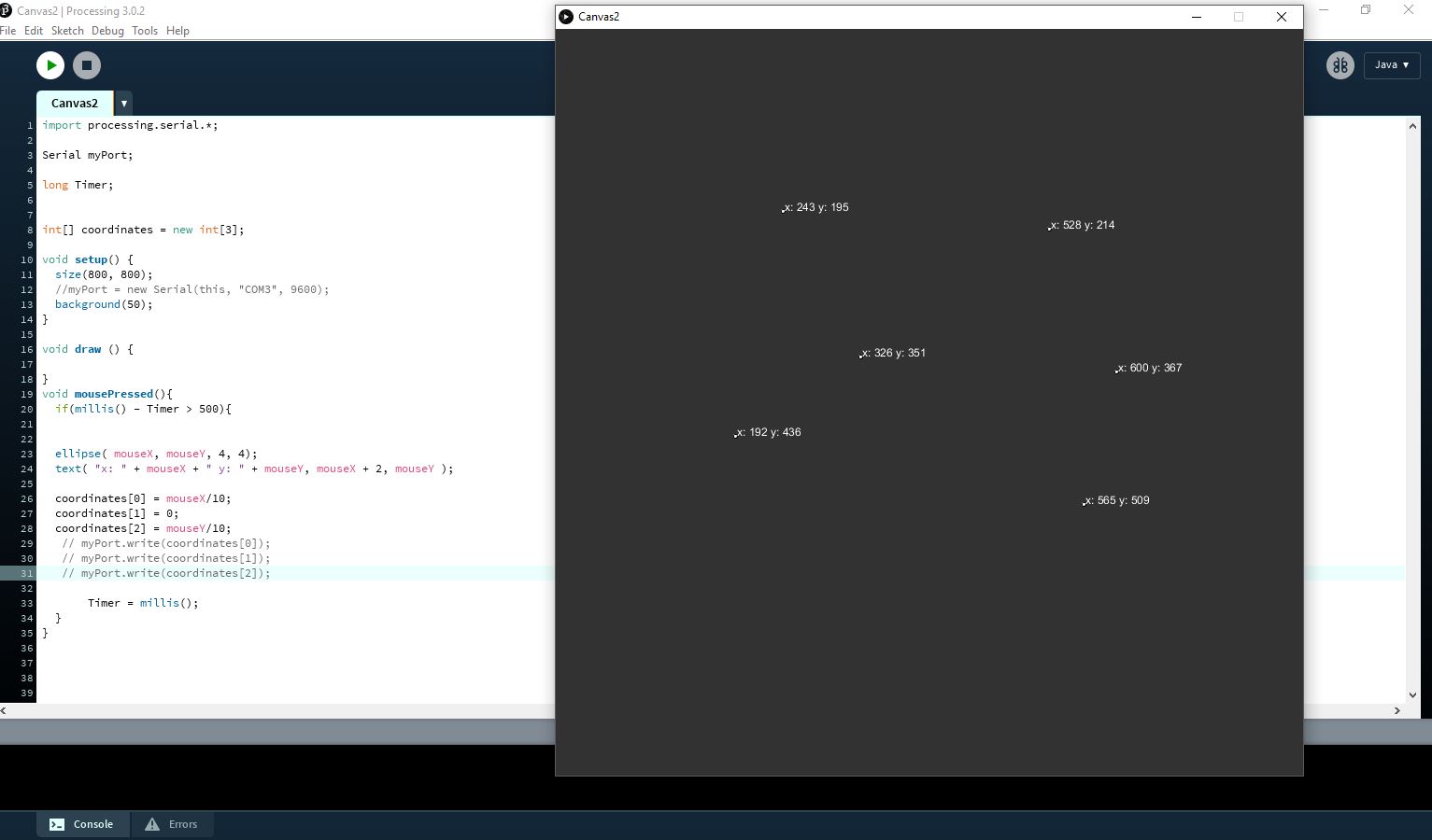
 In order to experiment a little and do some testing I built a simple interface in Processing that could send values to the Arduino over Serial. Note that the Arduino communicates to the Roland driver board through ISP.
I loaded the following sketch onto the Arduino, that simply uses the Roland library to control the spindle.
In order to experiment a little and do some testing I built a simple interface in Processing that could send values to the Arduino over Serial. Note that the Arduino communicates to the Roland driver board through ISP.
I loaded the following sketch onto the Arduino, that simply uses the Roland library to control the spindle.
#include < SPI.h>
#include < SRM20SPIRemote.h>
// SRM-20 Library
SRM20SPIRemote srm20;

long x =0;
long y = 0;
long z = 0;
void setup()
{
  Serial.begin(9600);
  srm20.begin(9, 6);
  Serial.println("Start!");
}

void loop()
{
  if (srm20.isReady()) {


srm20.getActualPosition(x,y,z);
Serial.print(x);
Serial.print("  ");
Serial.print(y);
Serial.print("  ");
Serial.println(z);
delay(500);
}

}
import processing.serial.*;

Serial myPort;
long Timer;
int[] coordinates = new int[3];

void setup() {
  size(800, 800);
  myPort = new Serial(this, "COM3", 9600);
  background(50);
}

void draw () {

}
void mousePressed(){
  if(millis() - Timer > 500){


  ellipse( mouseX, mouseY, 4, 4);
  text( "x: " + mouseX + " y: " + mouseY, mouseX + 2, mouseY );

  coordinates[0] = mouseX/10;
  coordinates[1] = 0;
  coordinates[2] = mouseY/10;
    myPort.write(coordinates[0]);
    myPort.write(coordinates[1]);
    myPort.write(coordinates[2]);

       Timer = millis();
  }
}
 Thing is that eventually I did not feel much comfortable in putting the two systems together, as both were too little stable and predictable.
Conclusions EMI is overall a highly conceptual project that failed almost miserably when it came to functioning properly. I have two semi-working halves, after all. To make it short, it was ambitious and it does not work as I had envisioned. But that is not such a bad thing in my opinion. I believe in explorations that lead to some unexpected ending or finding, but that is another story. I covered all the different techniques that I could use (I really used all the machines here!) and I learned a lot, both in terms of hardware design and electronics/programming. This time I really had to work starting from content, as 4 months of skill-based and centered work did pretty much kill my little creativity.
Grazie a Pietro, Matteo, Flavio for your precious help during the development of this project. Thanks also for calling me "Dora the explorer", making fun of my project and insulting the category of Interaction Designers as a whole. God could bless you all, cazzoni. Grazie at my FabAcademy instructor Fiore, and the other colleagues Diego Galue, Luca, Mario, Diego. Grazie also to the rest of the FabLab Santa Chiara Staff. Cool folks.
Table of Content
Resources
- [1] Shopbot Files
- [2] Lasercut Frame
- [3] Lasercut Back Cover
- [4] Handles
- [5] Board Eagle Files
- [6] Board Illustrator Files
- [7] Board Code