She really likes walking during rainy ugly days...
But she does not like to walk on dirty and dry grounds...
To be honest, Fab Snail does not like many things...like polluted air or muggy days...
She is not the only one who doesn't like all that, just like all the other snails...
The difference is that if Fab Snails is not happy, she can turns into a real stalker!
(Also on your mobile -.-)
So take care of Fab Snail, she is a good snail...
She is just different from the other snails!"
Weekly Assignment
The weekly assignment was:
- Measure something: add a sensor to a microcontroller board that you have designed and read it
Software and Hardware
The software that i've used this week are:
- CadSoft EAGLE PCB Design Software: used for designing the Schematics and the PCBs
- Fabmodules: used for creating the .rml files used for milling the PCBs
- Gimp: used for editing the .png files exported from eagle
Concerning the hardware:
- Roland SRM20: CNC mill
PCB Design
My idea for the first board, was to make a PCB with 2 of the 3 sensors that i'm planning to use for my final project:
a temperature sensor and a photoresistor.
I've started by taking a look at the boards designed by Neil here.
In particular, i've considered these two:
Phototransistor board
Thermistor board
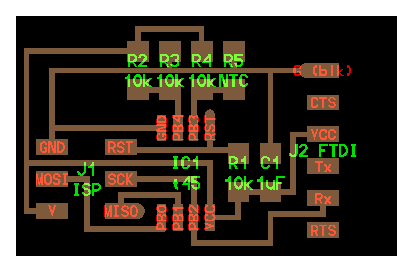
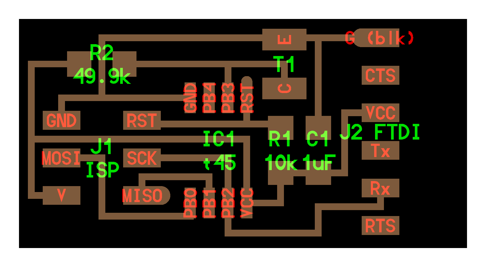
I've then tried to mix the two boards togheter and i've designed this in eagle:
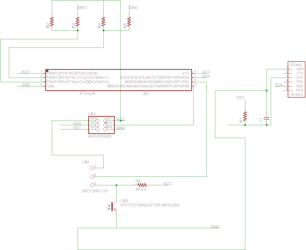
Schematic:
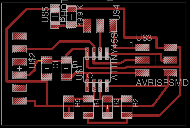
Board
This is the BOM (bill of material) that i've used:
| Code | Description | Quantity |
| 223-2394 | 10Kohm resistor | x4 |
| 223-2265 | 49.9Kohm resistor | x1 |
| 696-2513 | ATtiny 45 microcontroller | x1 |
| 766-1062 | 1μF capacitor | x1 |
| 682-1406 | Thermistor | x1 |
| xxx-xxxx | Photoresistor | x1 |
| 223-2394 | Switch | x1 |
This is the milled board:
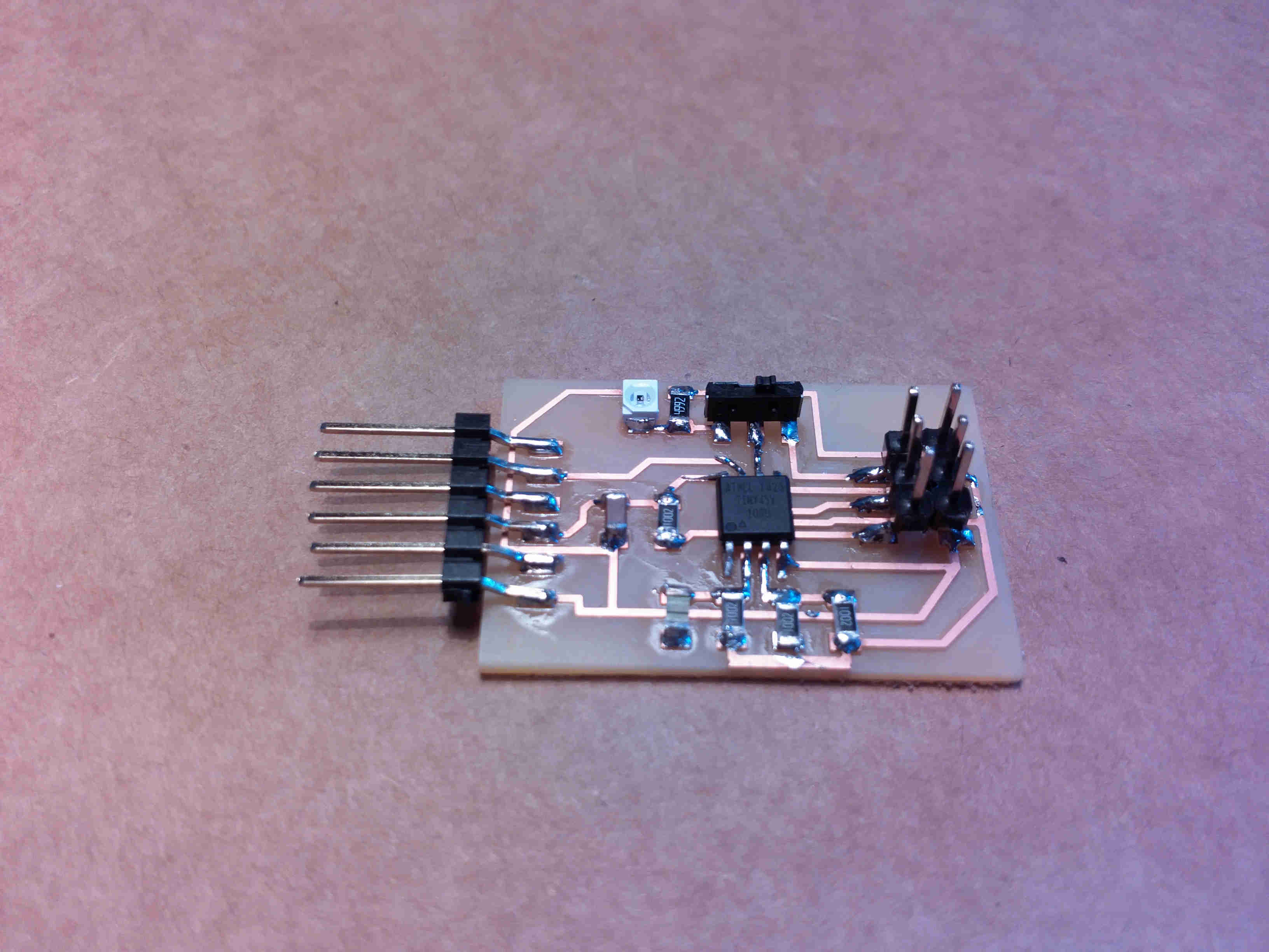
I've just added a switch to the components used for the other boards. The aim of the switch was to connect alternatively the MISO pin of the SPI connector or the Phototransistor to the PB1 pin of the MCU. In this way, turning the switch on the left allowed me to program the board through the FabISP while moving to the right position, the switch connects the PB1 with the photoresistor.
Programming & Testing
To program the board i've used the FabISP board builded in week4.
I've used the following files to program the board through the same procedure described in week6
The thermistor works fine and it reacts to temperature changes.
At this point i wanted to test the other sensor before trying to write a program to use both sensors togheter. Then i've downloaded Neil's code hello.light.45.c. Because of the fact that i've already used the ADC of the MCU in week8, i knew that i had to change the ADMUX register to connect PB1 (the pin to which i've connected the photoresistor).
So i've edited this part of Neil's code changing the value of MUX1 to 0 so i can connect PB1 to the ADC:
...
...
//
// init A/D
//
ADMUX = (0 << REFS2) | (0 << REFS1) | (0 << REFS0) // Vcc ref
   | (0 << ADLAR) // right adjust
   | (0 << MUX3) | (0 << MUX2) | (0 << MUX1) | (1 << MUX0); //
ADCSRA = (1 << ADEN) // enable
   | (1 << ADPS2) | (1 << ADPS1) | (1 << ADPS0); // prescaler /128
   ...
   ...
But this time the code did not worked and i was not able to read any output from the sensor.
I've started first to check the electrical connections but everything seemed to be fine.
In the end i've realized that i've committed a huge mistake in the design of the board.
Reading the datasheet
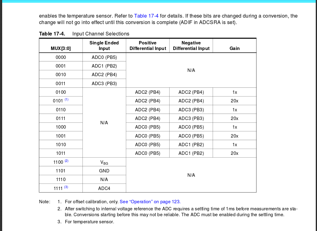
at page 134, i've realized that PB1 is not selectable as an ADC input. At this point i must admit that, nevertheless the mistake that i've commited, i was very happy to be able to find what was the error by reading the datasheet of the sensor.
As shown in the table, i've found that only PB2,PB3,PB4 and PB5 are selectable from the multiplexer.
UPDATEs
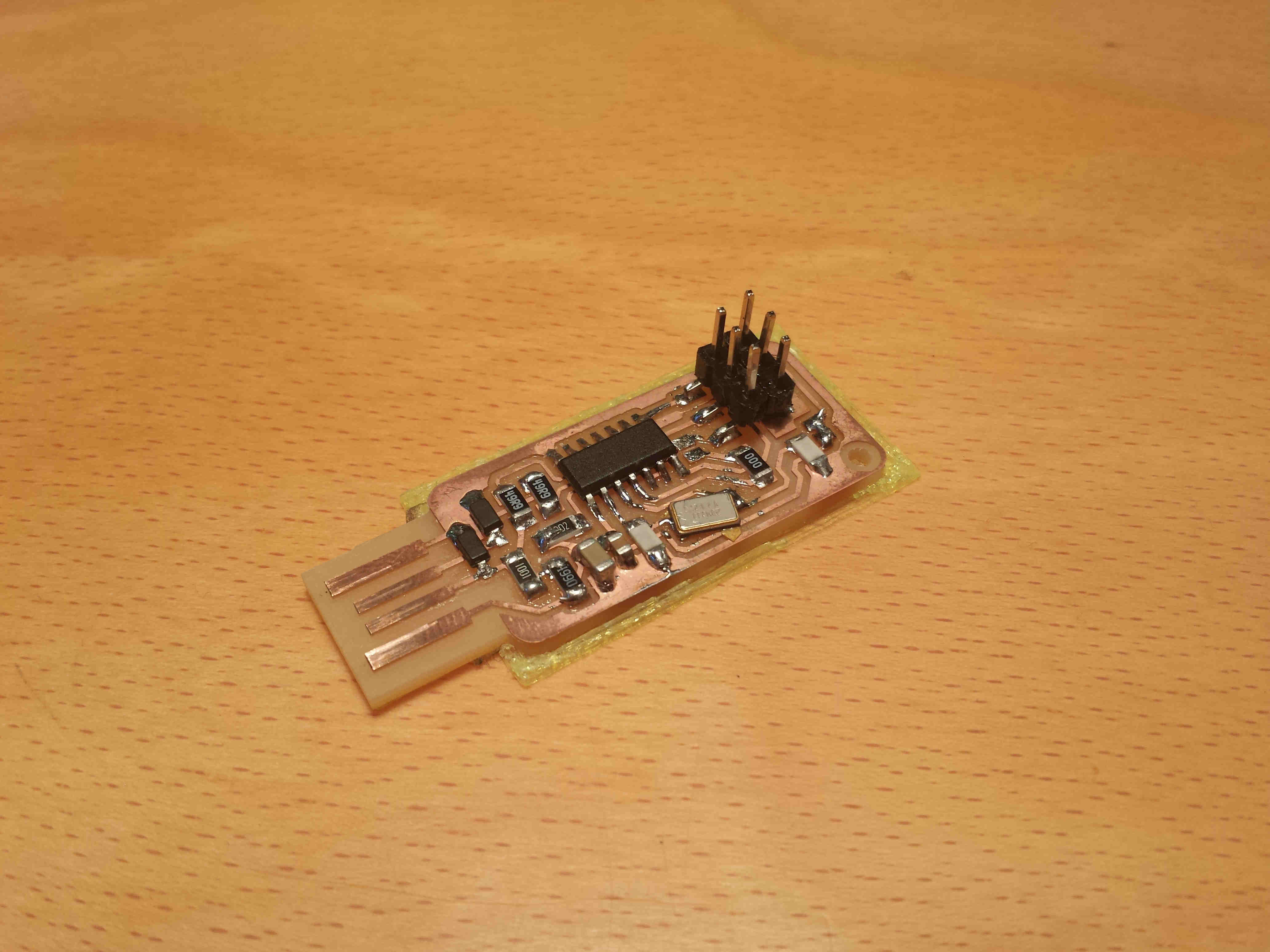
- I've builded another input device board during week13; it is a pyroelectric sensor board. Follow the link to check it out.
- I've used both a thermistor and a phototransistor in my final project and i've designed a breakout board for the Particle Photon
- Python program (executed with python 2.7)
Conclusions
I want to use both the thermistor and the phototransistor in my final project because i want the Snail to be able to read theese two kind of data from the Snail's horns. I failed in combining the two boards but i feel happy because i was able to discover which was the mistake by reading the datasheet of the MCU. By the way, i found this week partcularly useful in order to have a complete overview on which are the most important input devices that is possible to control through an MCU. I think that when you need to read multiple sensors, is more convenient to use an MCU with more pins (especially to deal with ADC).