Week 9 - Mechanical Design
Make a machine: the passive parts
Steps:
* Choose a concept and design a machine
* Build the passive parts and operate it manually
PluriBot
For this week's assignment, after a brief session of brainstorming, we decided to design a CNC machine to automatically fill bubble wrap with fluorescent liquid. The idea is to combine pixel art with gel tonic water, recycling used bubble wrap to make something artistic.
Since we planned and built everything together, we shared the effort, so that everyone of us had the same knowledge of the machine.
Build the passive parts
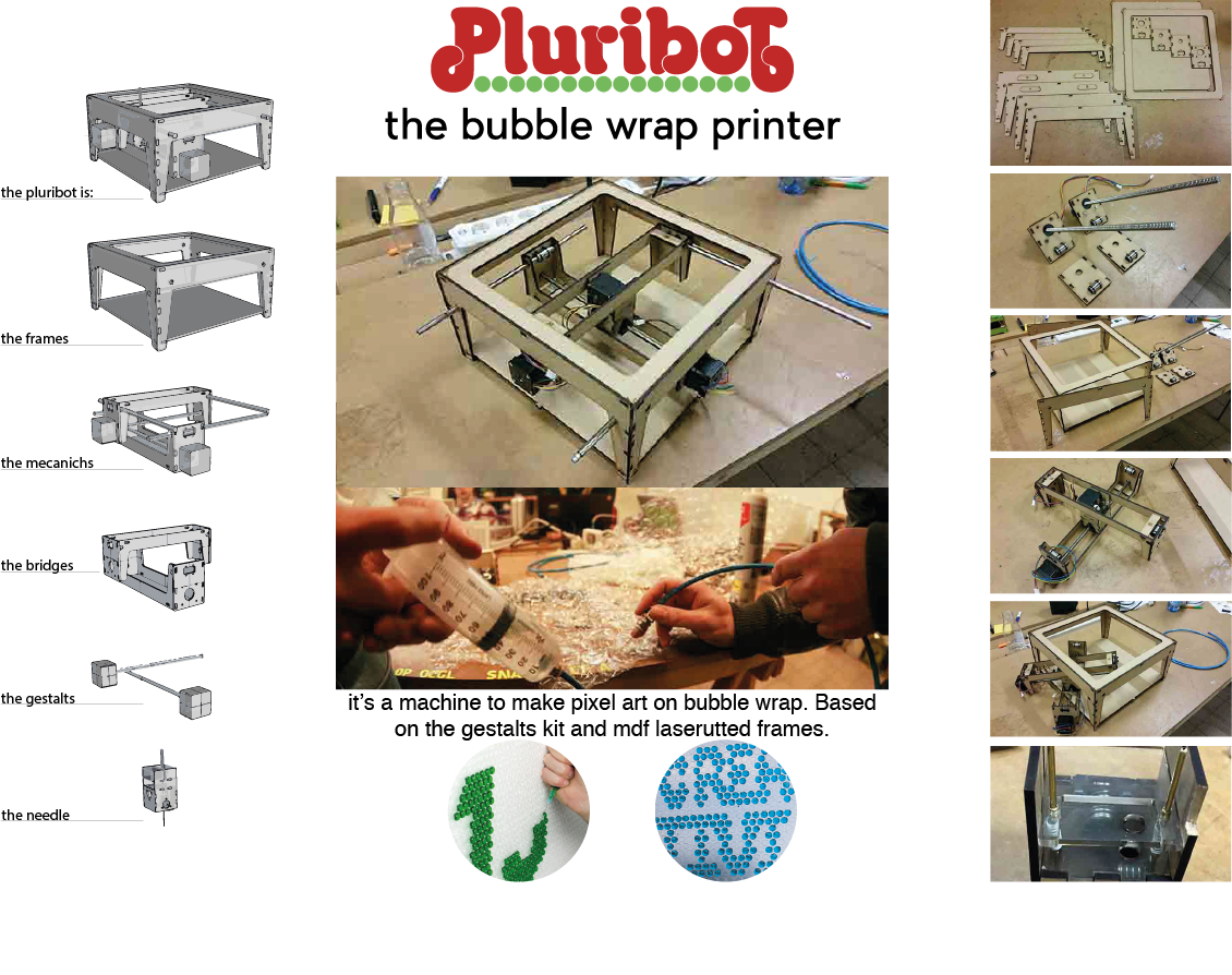
Since we had to use the motors included in the kit, that are motorized lead screw steppers, we decided to build an X/Y gantry
system, taking cue from the Ultimaker Original 3D printer.
In this kind of system, the extruder (or in our case the actuator) is placed in the intersection of the lead screws and moves along the X/Y directions, thanks to the force applied by the motors
to it.
After mounting the X/Y system, we tested it moving the lead screws by hand and checked that everything worked as
expected. The linear rails we received in the kit were really awful, so we swapped them with 8mm straightened steel linear rails,
and the movement improved really much.
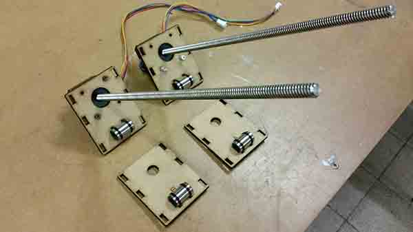
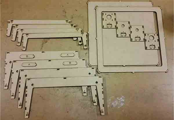
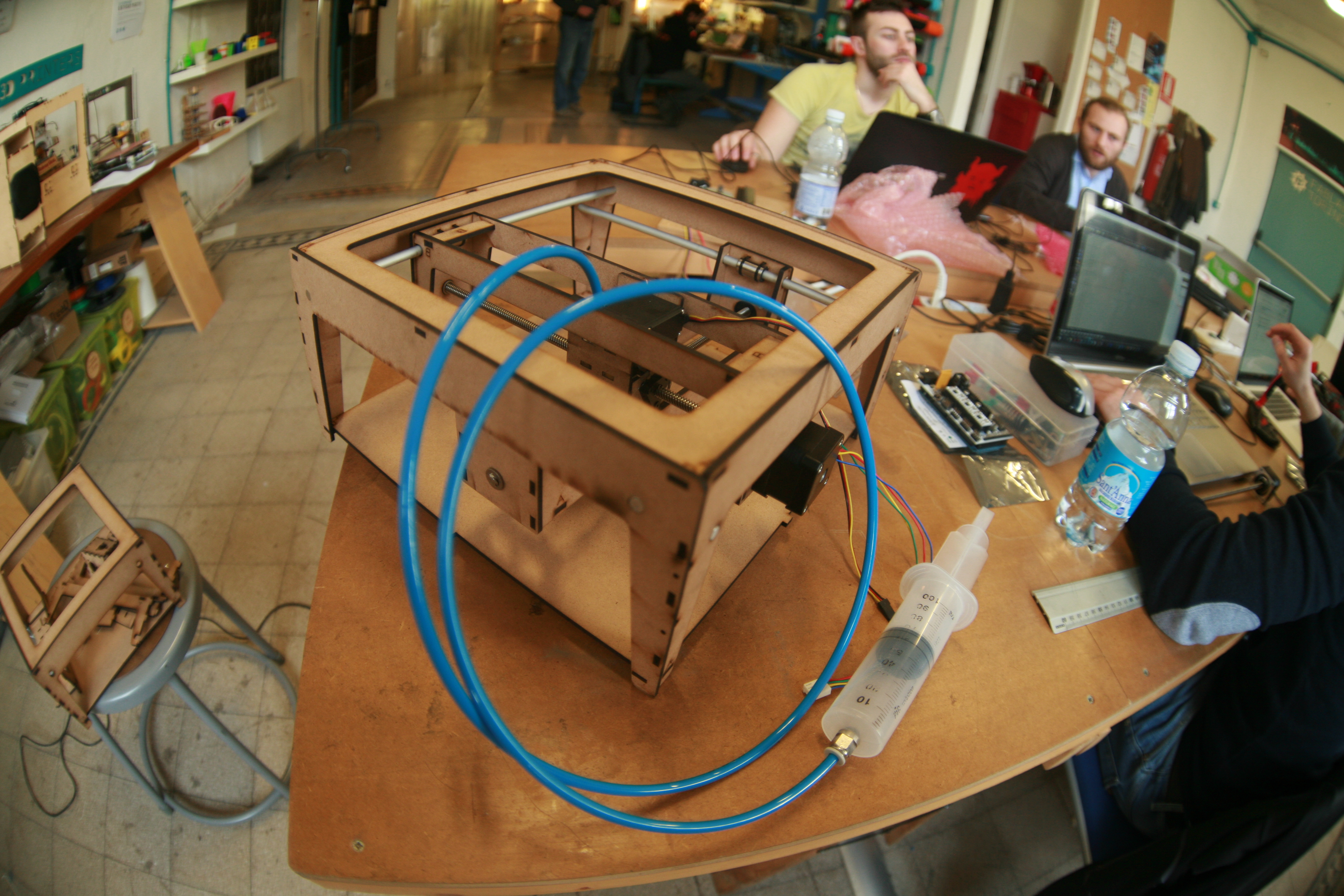
To make the machine more solid and reliable, we designed a frame that can be laser cut from a sheet of 4mm MDF, and mounted
without glue or screws just by press-and-fit. The result was a sturdy square frame, with holes to keep in place the linear rails,
and with openings on all sides to make easy the assembly of the whole structure.
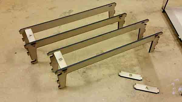
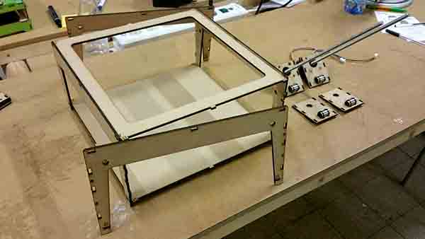
When the assembly was complete, we tried once
again to move manually the motors and we checked that bearings were sliding smoothly on the rails. To stress a bit the system, we
even tried to move the lead screws attaching an electric screwdriver to them and driving them "speedly".
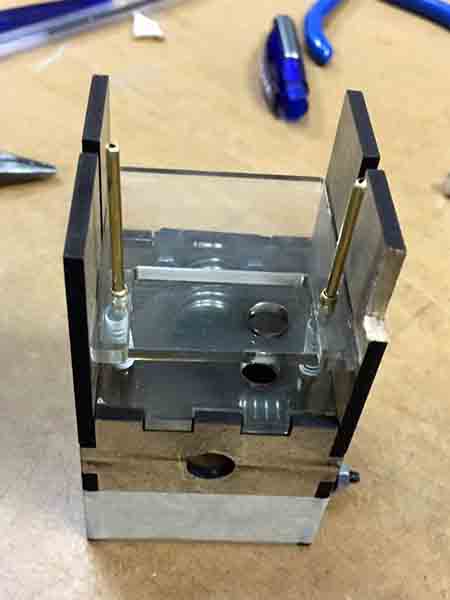
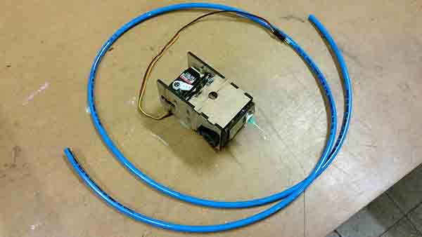
The most complex piece of the machine was to design a compact and functional needle actuator to cut through the pluriball and
inject the material. At the beginning we thought to use a 3rd motorized lead screw to move up and down the needle, but we abandoned
this idea since this solution seemed too bulky and cumbersome. So we racked our brains and we came up with a more compact design
based on the use of a servo motor to push down a structure holding the needle, and on the use of springs to make the structure
go up.
In this way we managed to fit the needle, the rubber hose for the liquid, the servo motor, the tiny rails and the
springs all inside the "extruder box", exploiting the free space between the leaded screws.
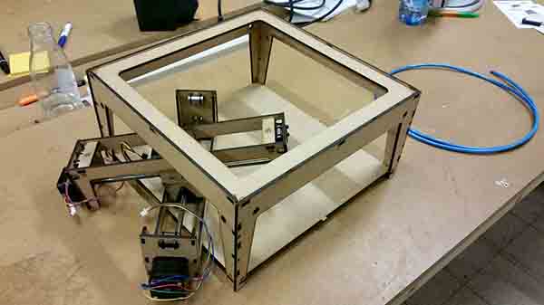
The final part was to assemble everything together and try the whole system. Everything worked ok and the assembly was completed in a couple of hours.
Here the final 3D modeled file. Stefano Paradiso and I worked together and at least I prepare the nesting for laser cut it: you need just a sheet of 4mm MDF 1200x900mm.
RETURN UP
| ← Week 8 / Embedded Programming | week 10 / Machine Design → |
|---|