- Stefano Galbo
Beginner
Scheme
More than previous weeks, this week I don't understand completely what I'm going to do.
I don't know nothing about electronics, so I don't know differences between components, their rapresentation, and possible problems for traces.
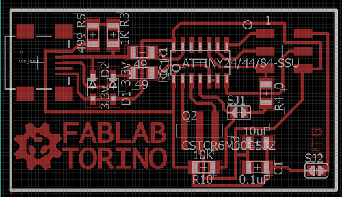
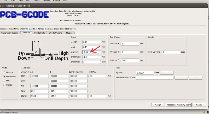
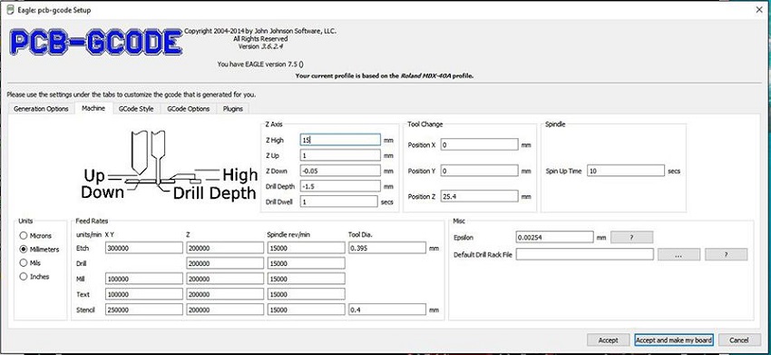
We are started from FabISP called "David",a little bit modified by our instructor Federico Vanzati , and using Eagle 7.5.0 with Pcb-Gcode plug-in we tried to set milling machine to make the board (scheme, board).
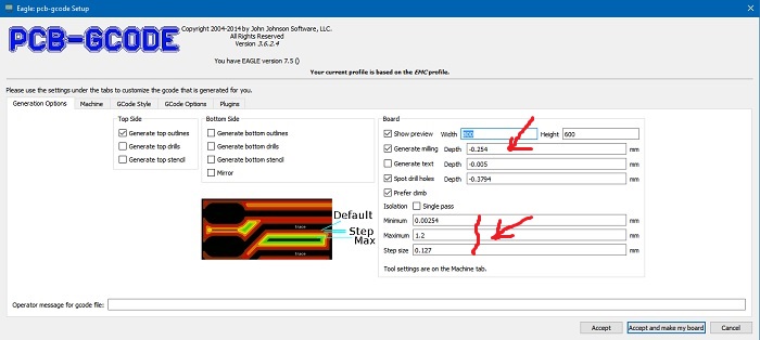
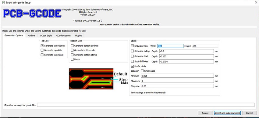
Our instructor showed us parameters he used the day before, I didn't understand all of them, but I understood that most important are Z down, generate milling and traces size.
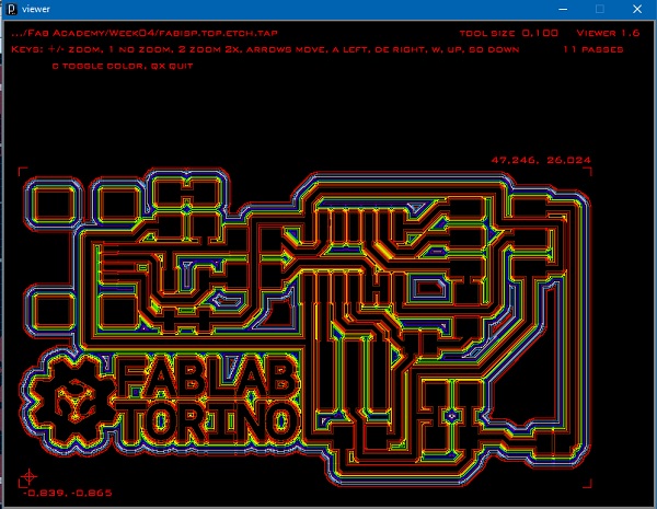
Viewer showed me traces that machine should have done, and I had to check them: I had to compare preview with scheme, to be sure that there were all the traces and that machine had necessary space to make traces between components.
Milling
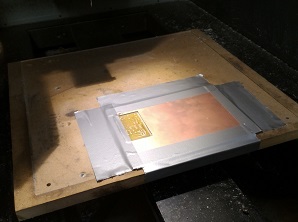
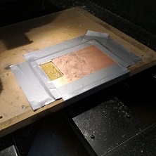
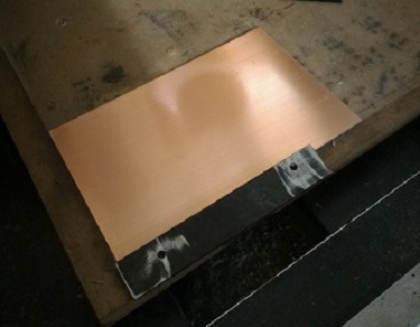
First we put copper base in the milling machine, and fixed it with scotch tape. Then we spread a little bit of grease on the copper base, in order to reduce friction of mill on it.

Now I have to set X,Y,Z origin: for XY origin it's very simple, I calculated approximate size of board, I moved mill on XY plane (considering that mill starts at bottom left of scheme) and I pushed "Apply" botton in "Set XY origin".
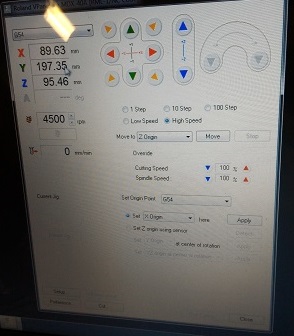
For Z origin precision is essential! A little mistake could abort final product.
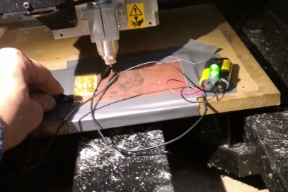
In my FabLab we have an useful device, a simple circuit which switchs on a green led when closed: we put one terminal on copper base, and other one directly on the mill. When green led lights up, it means that circuit is closed, because mill touches copper base.
Then we moved the mill on Z axis near the base (more or less, 1 mm of distance), we set steps of 0,01 mm, and we stopped moving as soon as the led lighted. We repeated the same operation at different points, in order to obtain an average Z position. Finally we applied Z origin.
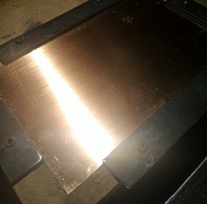
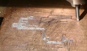
I started milling, and after about 25 minutes process finished, but I wasn't satisfied at all by results. I repeated procedure many times, but boards were all completely unusable.
There were two orders of error:
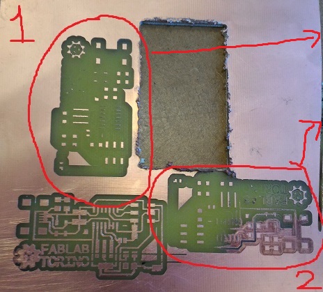
1) Human error: we set wrong milling parameters in PcbGcode program, so mill removed too much copper.
2) Materials: mdf support and copper base weren't level, scotch tape couldn't reduce error enough, so mill worked on different heights.
Corrections
Remedy for first problem was to recalculate all parameters and try to modify them, here values I'll use (without "FabLab Torino", to save time):
Second correction was a more attention on behavior of mill in Z axis.
We supposed that schotch tape wasn't best way to fix and to level copper base, so our instructor Stefano Paradiso thought a mechanical way: it will be helpful both for leveling uniformly the board and for making easier small movements by screw spins.
Although we were very accurate in setting Z origin and in leveling copper base, result was still bad.
This is the worst problem I found in this machining procedure, that a precision of decimes of millimeter is required with materials such as mdf plane, scotch tape, milling machine..they can't be. I have seen other boards on web by chemical etching..those are accurate!
I used a simple stratagem to resolve the problem:
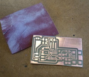
I let milling machine work few seconds, so I could see that on right side it didn't cut enough; I stopped the work, I reset Z origin 0,01 mm lower and I restarted the work.
In this way, the left side will be a little bit more remarked, but the right side will be perfect!
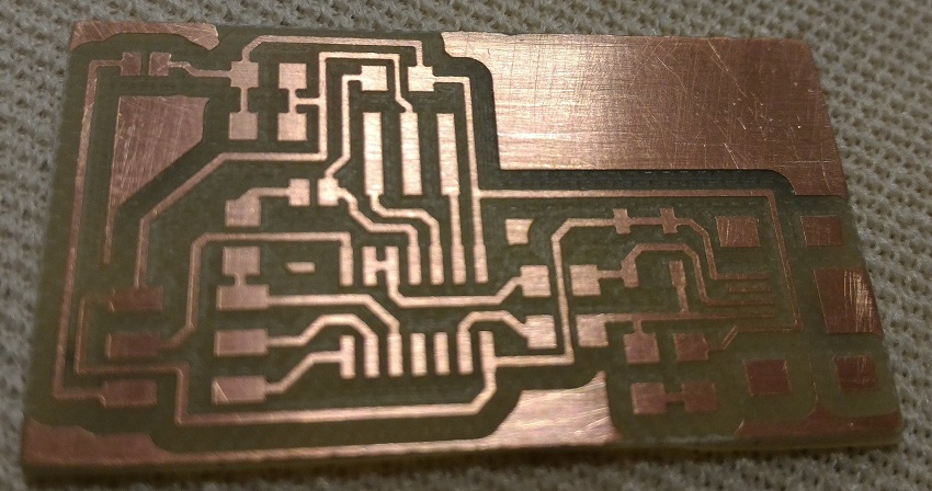
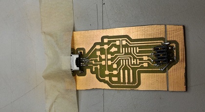
With sandpaper I removed excess copper, I cleaned the traces, and my board is finally ready!
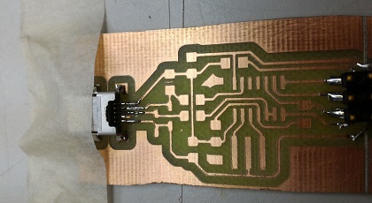
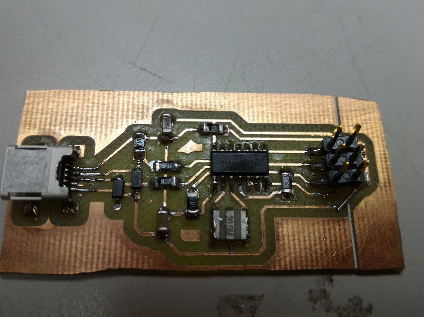
Soldering
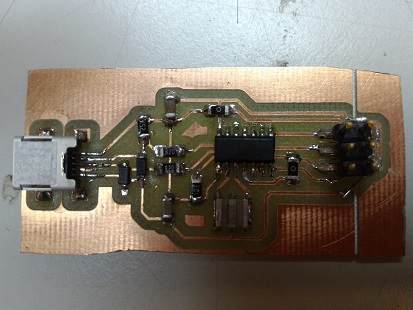
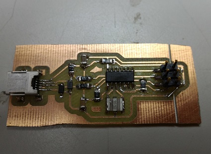
This is my first soldering operation: pcb just milled didn't work, so I used another one even though it had a wrong cut on a route. I will resolve with a "tin bridge".
It was a little bit complicated to clamp the pcb and be accurate with so little components, but tin of 0,5 mm (instead of 0,75 mm) helped me.

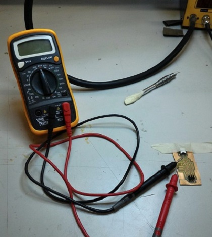
Tester was very helpful, I was never sure of my solderings so after each of them I tested good connection between route and components, but also no wrong connections between different routes or different components.
Programming
This part is very hard for me, I have never programmed anything, so I follow this tutorial slavishly, with the valuable support of my classmates Gianfranco Caputo and Stefano Paradiso.
- I downloaded WinAVR (fortunately my path saved!), Windows 10 drivers and FabISP firmware.
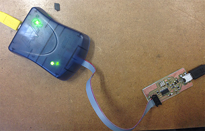
- I connnected my FabISP with PC and ATAVRISP2 programmer: the light was green...good!
- In order to program my FabISP, I opened commands prompt and I navigated to the directory where I had the firmware. Then I wrote "make clean" and "make hex."
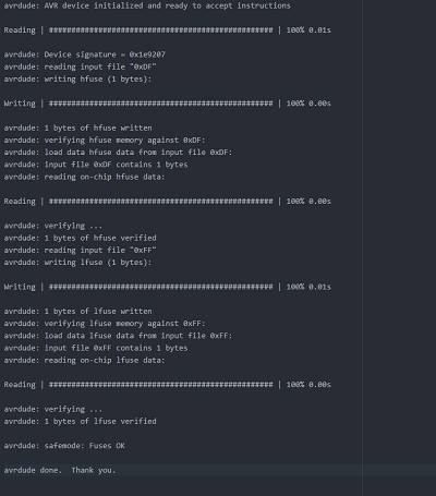
- Now I set the fuses so my ISP will use the external clock instead of internal one: I have to write "make fuse"
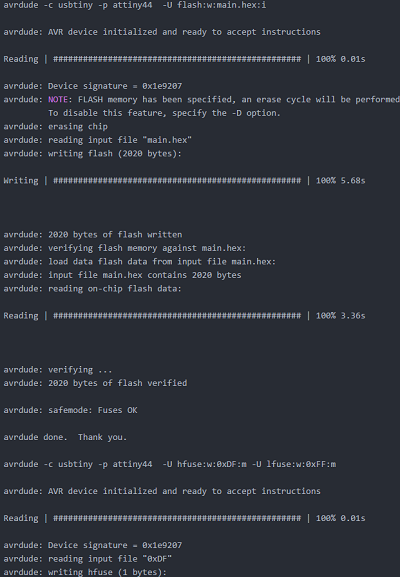
- Finally I programmed my ISP to be a programmer, with "make program".
- When everything seemed correct, I went to my device management but my FabISP was not recognized...damn! I don't know why, I hope to discover it in the next days.