week 6
Electronics Design
Redraw the echo hello-world board(s)
Add a button and LED
Check the design rules, and make it

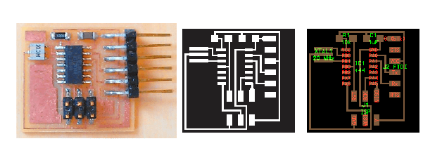
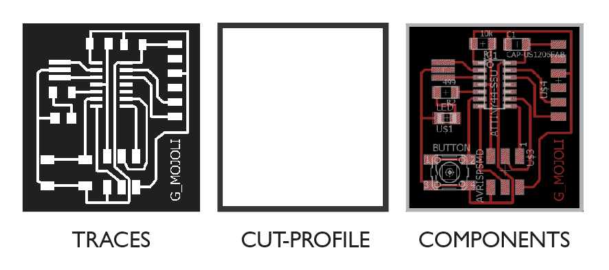
This week, we designed electronics boards by modifying the Echo Hello-world board, adding a button and a LED. In the next image displays the tracing.png and the components.png
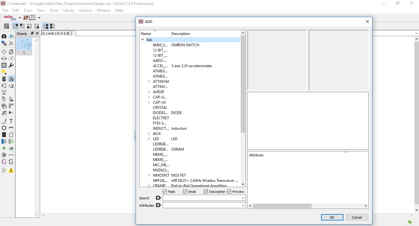
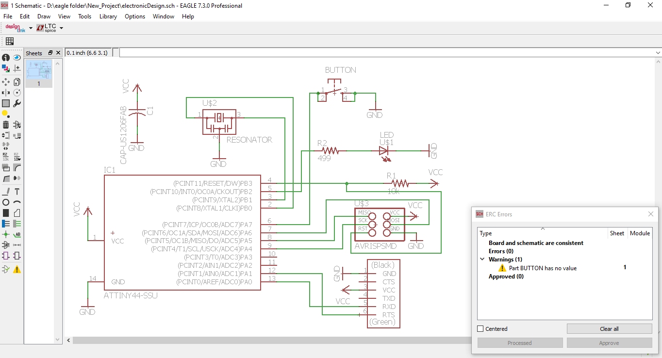
The first step was to design the circuit in Eagle. I created a project and then created a scheme within the project. I used the file fab.lbr common components provided to add to my library Fab Lab Eagle. Once the scheme finished, I check for any errors in connection with the command ERC Electrical Rule Check. Given that is my first time to design a board.
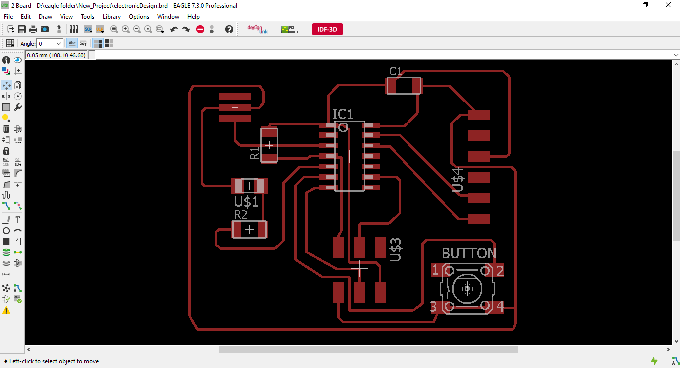
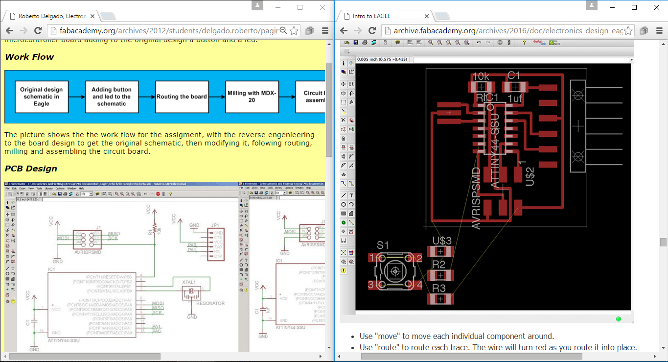
The next step was the creation of the tracks. I created a table schema by clicking the "Generate / switch to raise" button. I tried to create my own track with the Autorouter, but it generated in two layers. So I decided to draw on their own following the fab tutorial example and the assigment of my tutor Roberto Delgado.
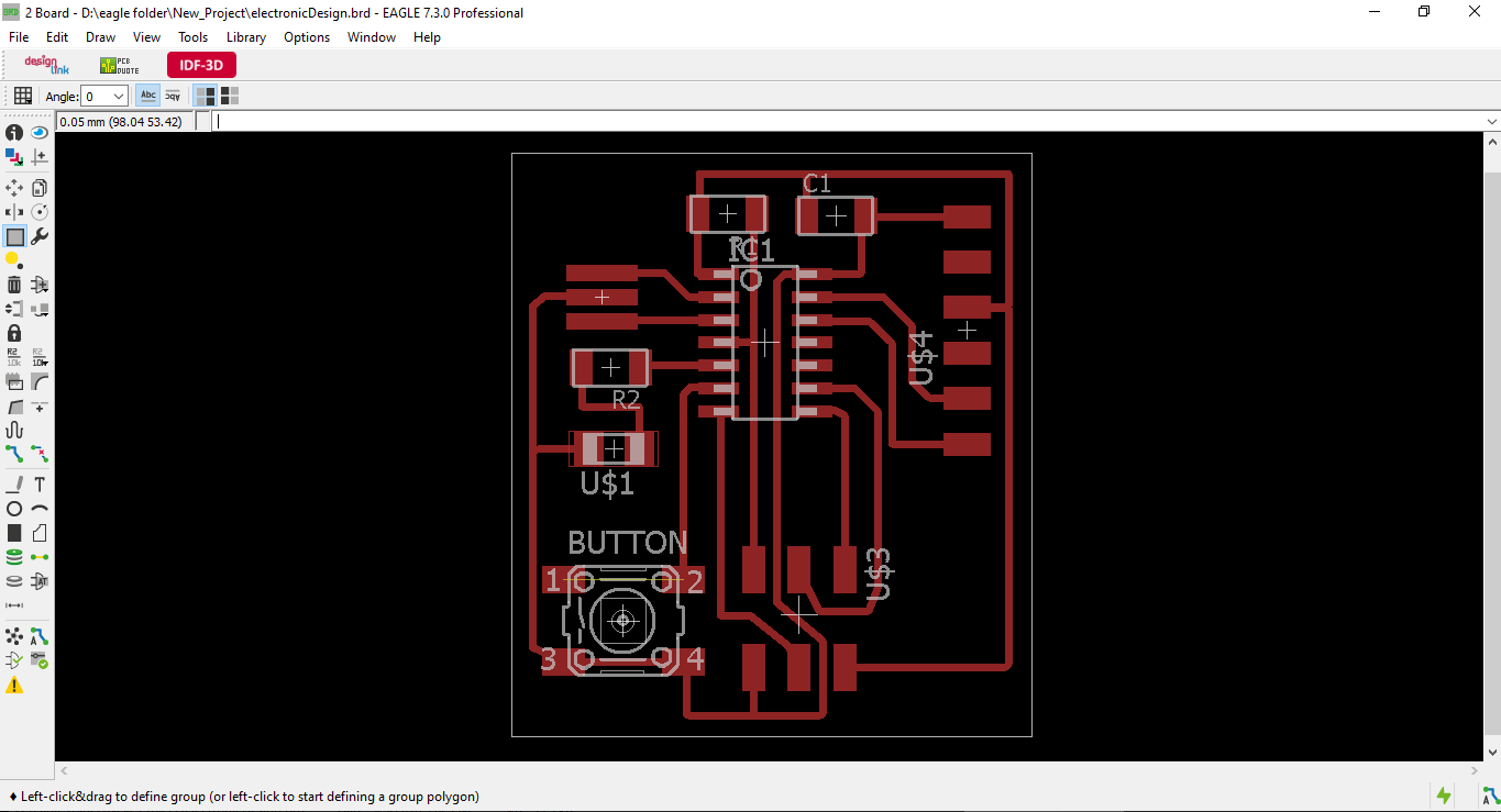
Next I made a box around the traces and shrunk the workspace around the box. This allowed me to export a png with only the bottom layer visiblie in order to create the profile cut. I exported one png for the profile cut, one for the traces (adjusting layer visibility each time) using the settings monochrome and 500 dpi. And one for the components to guide me in the soldering.
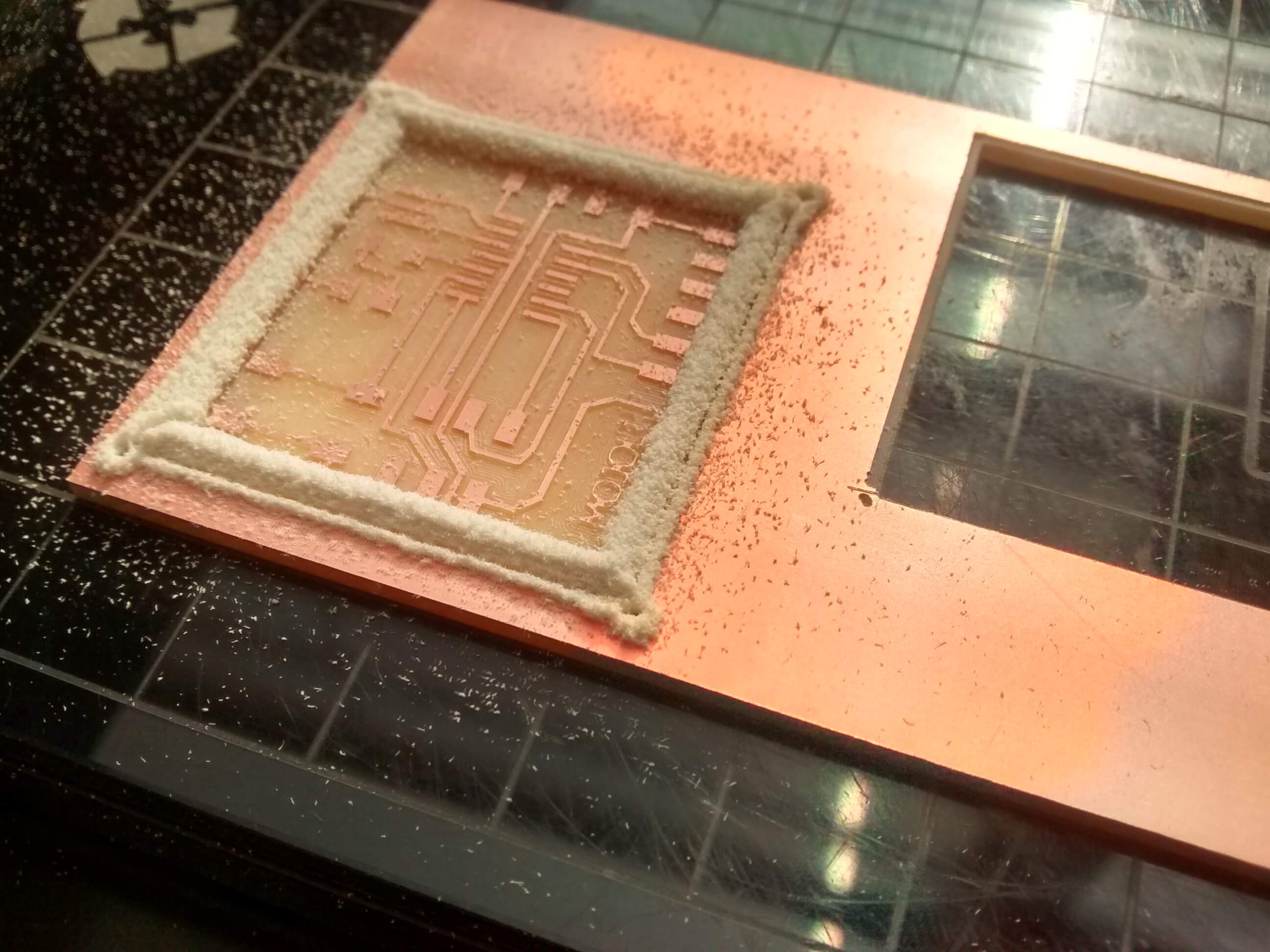
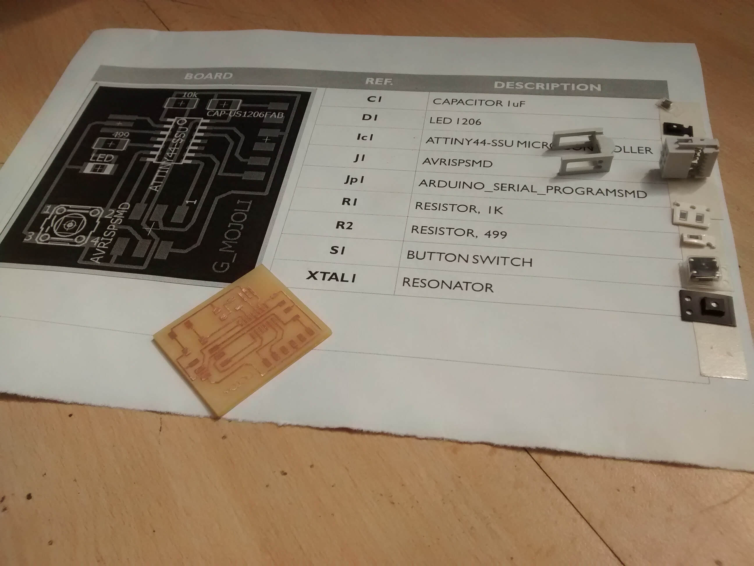
The rest of the fabrication was exactly the same as for the FabISP In-Circuit Programmer (load pictures into the fab module, send to Modela, 1/64 mill for traces, 1/32 mill for profile, clean, flux, solder, remove flux). I used a components list with the components.png to guide me in the soldering.
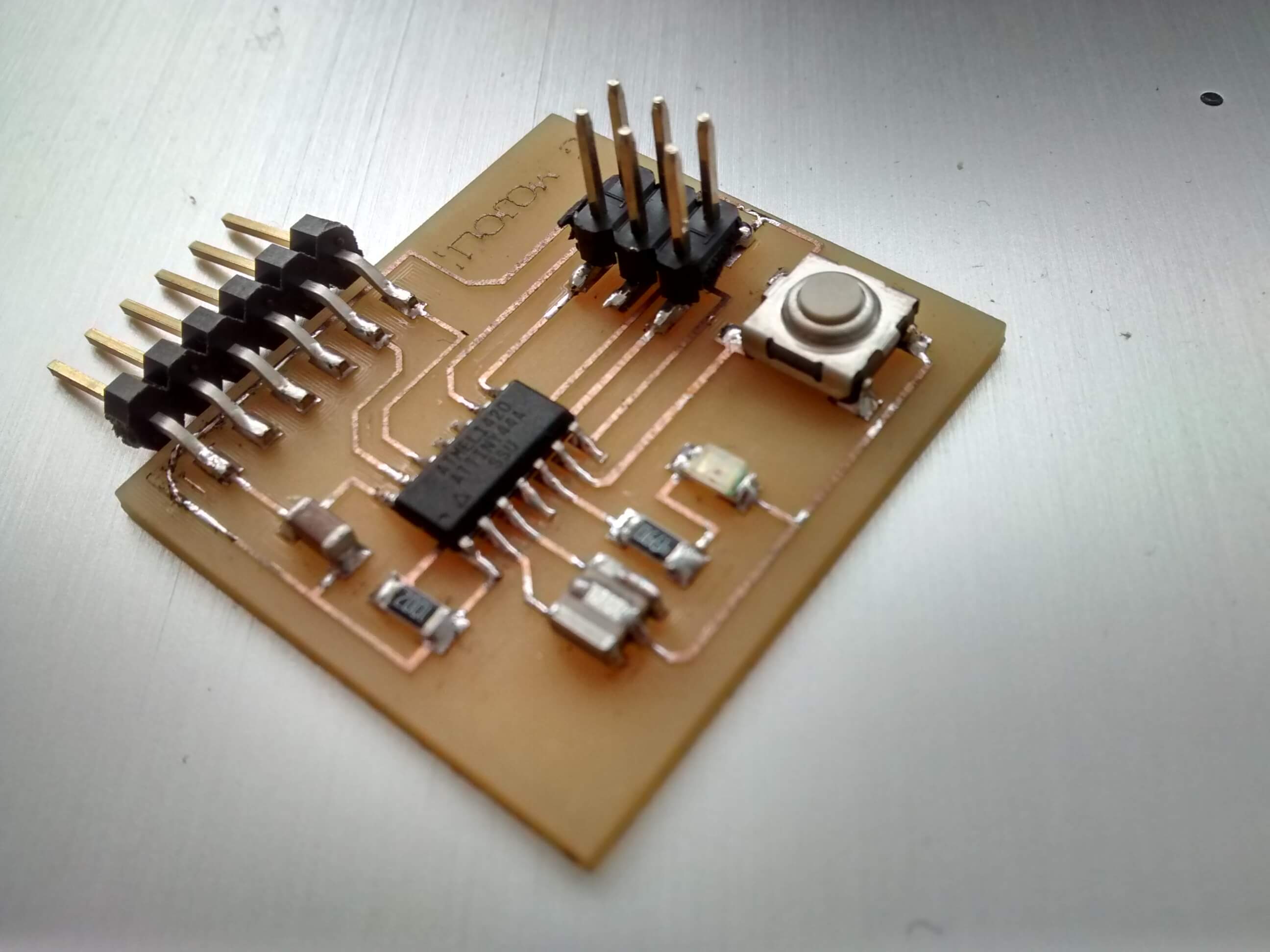
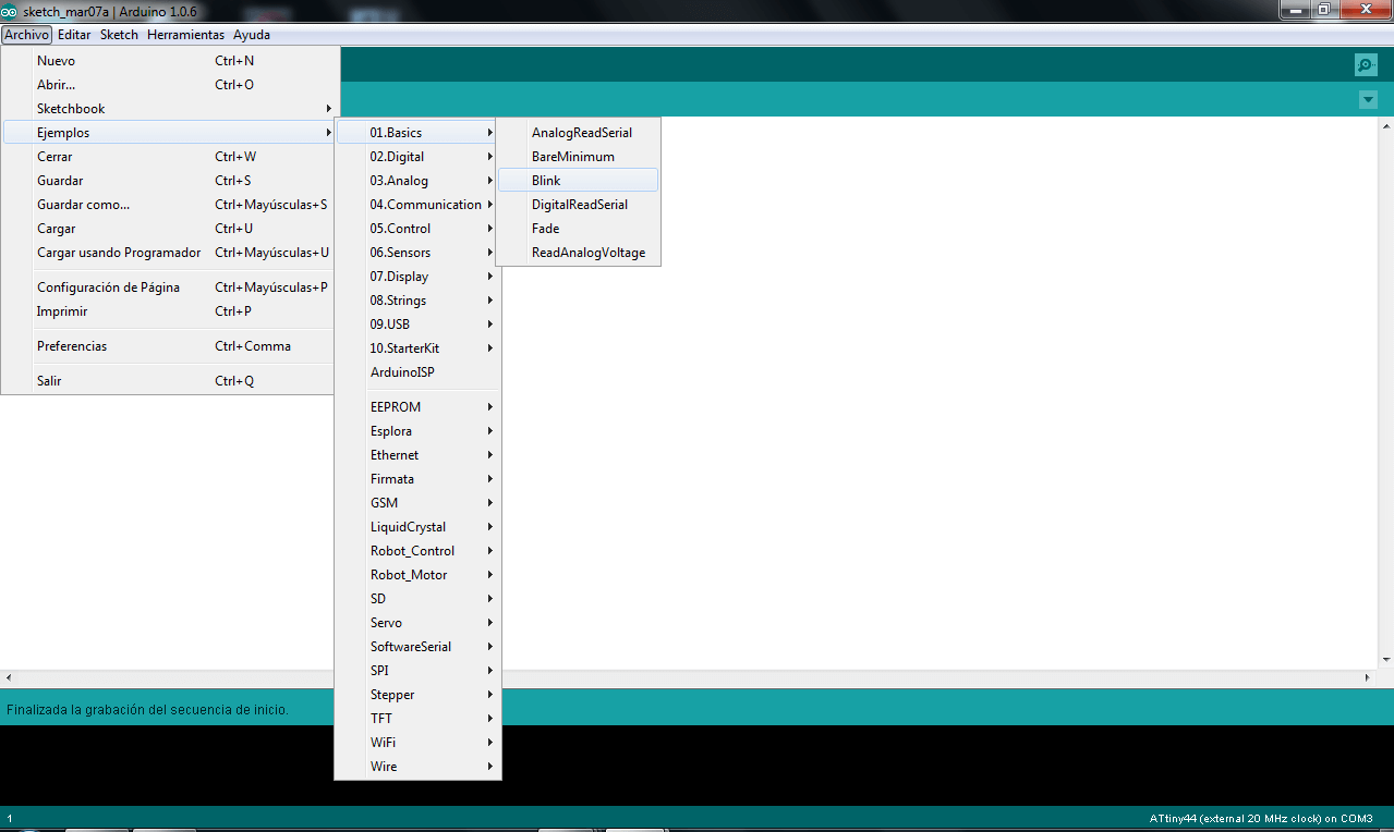
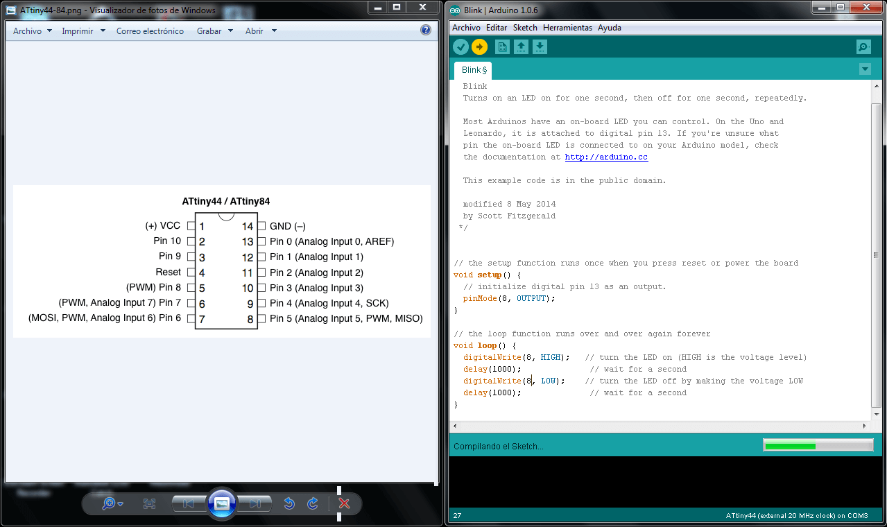
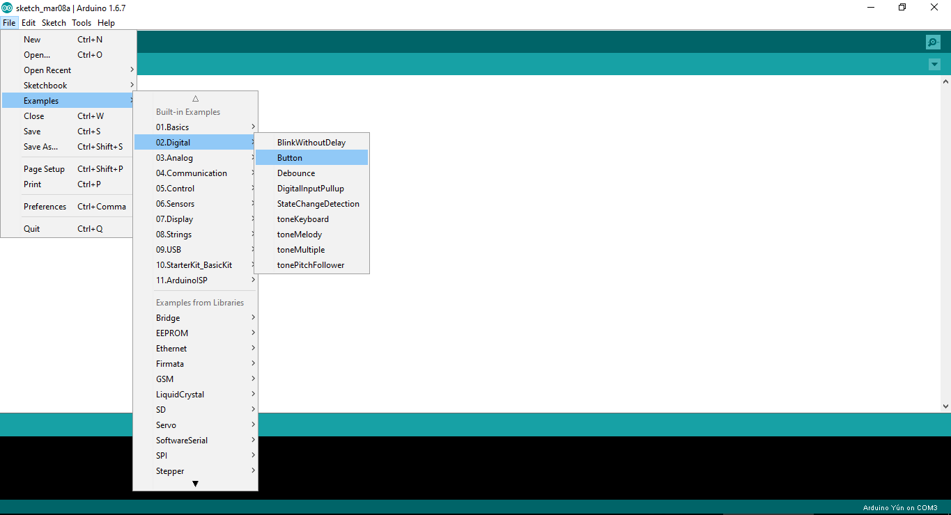
To load the firmware and program the echo hello-world board, we use Arduino and the ISP board.Here you can see a useful tutorial, was used as a guide.
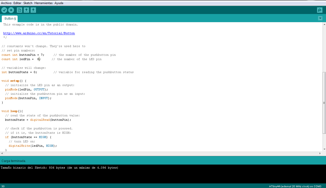
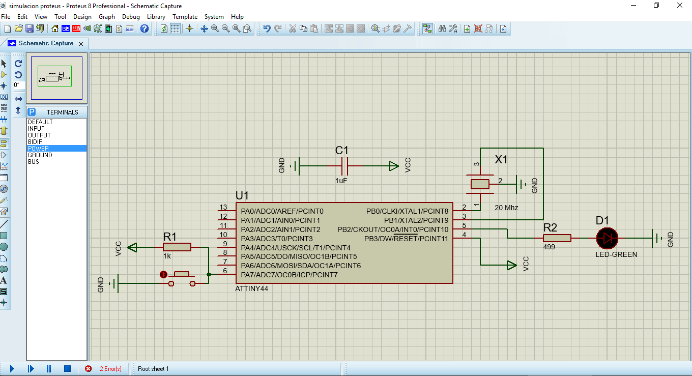
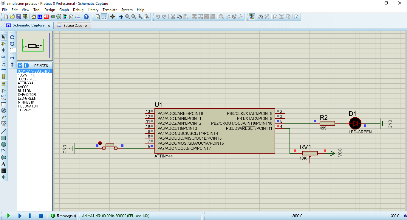
I tried to perform the simulation in Proteus, but did not get the expected result, first did not recognize me the resistor value and generated an error, to erase the schematic, allowed me to run the simulation but without turning on the LED, and so far I could not detect the problem.