week 13
Output Devices
Add an output device to a microcontroller board you've designed
Program it to do something

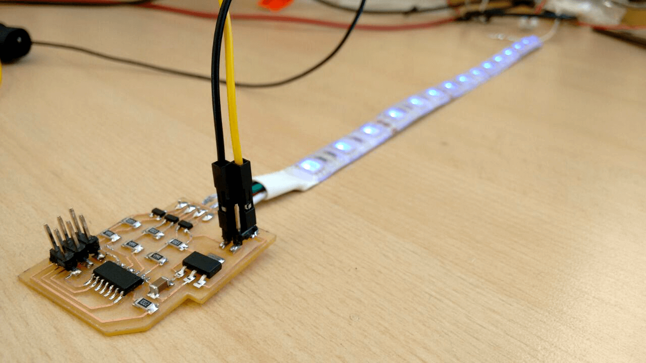
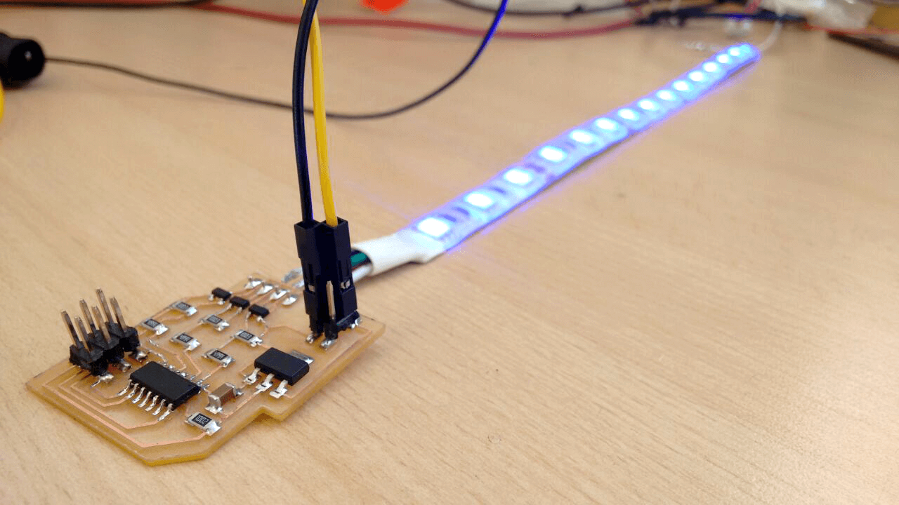
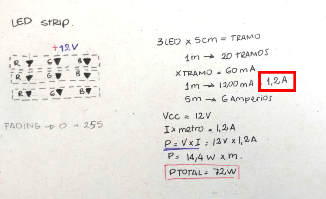
For this week we have to add an output device to a microcontroller board that I have designed and also program to make something. I'll be working with a LED strip as an output because that will be useful for my "Portable product photography studio" final project.
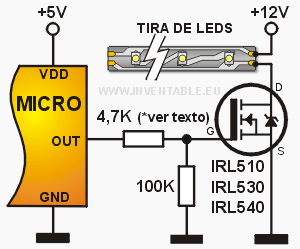
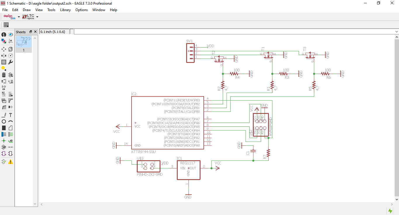
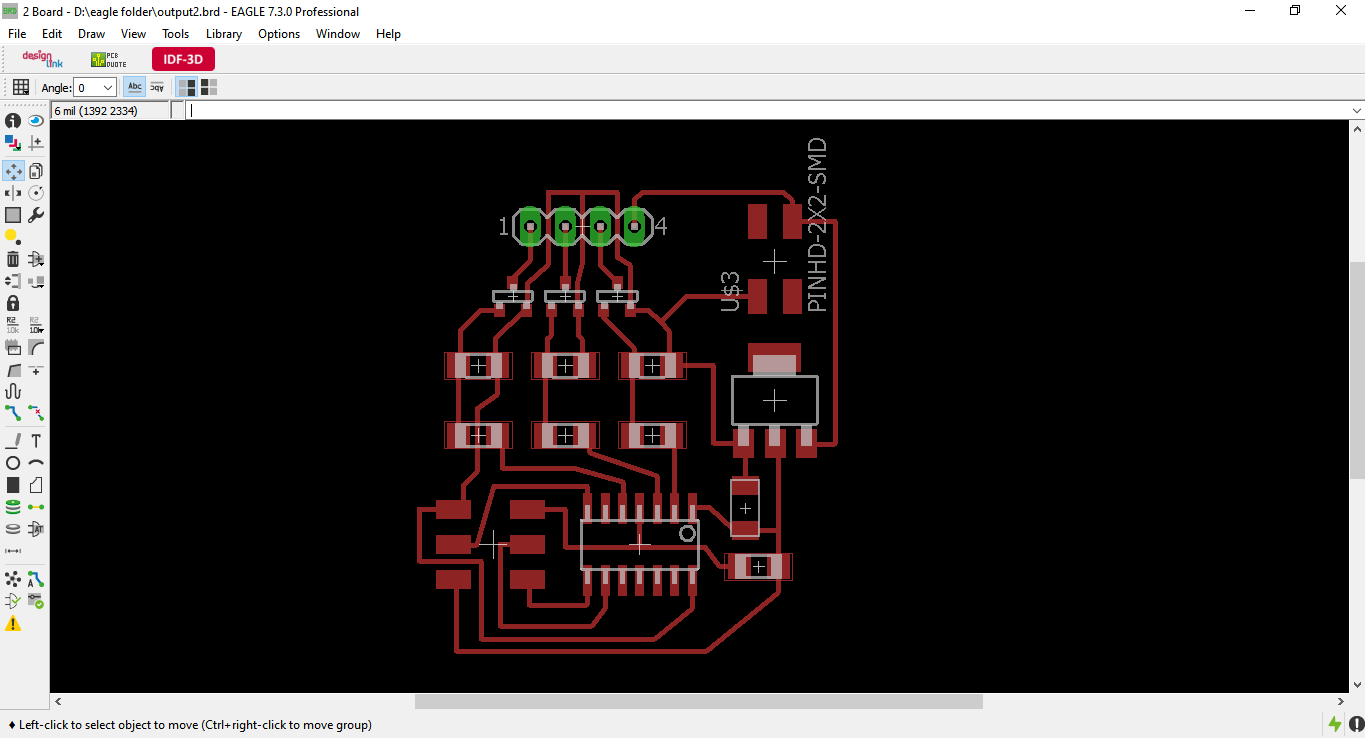
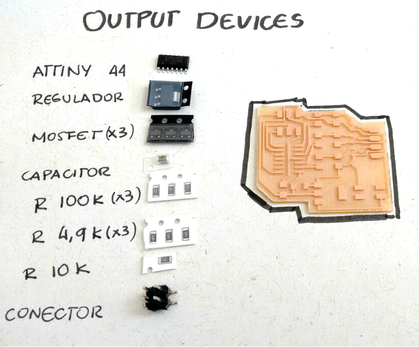
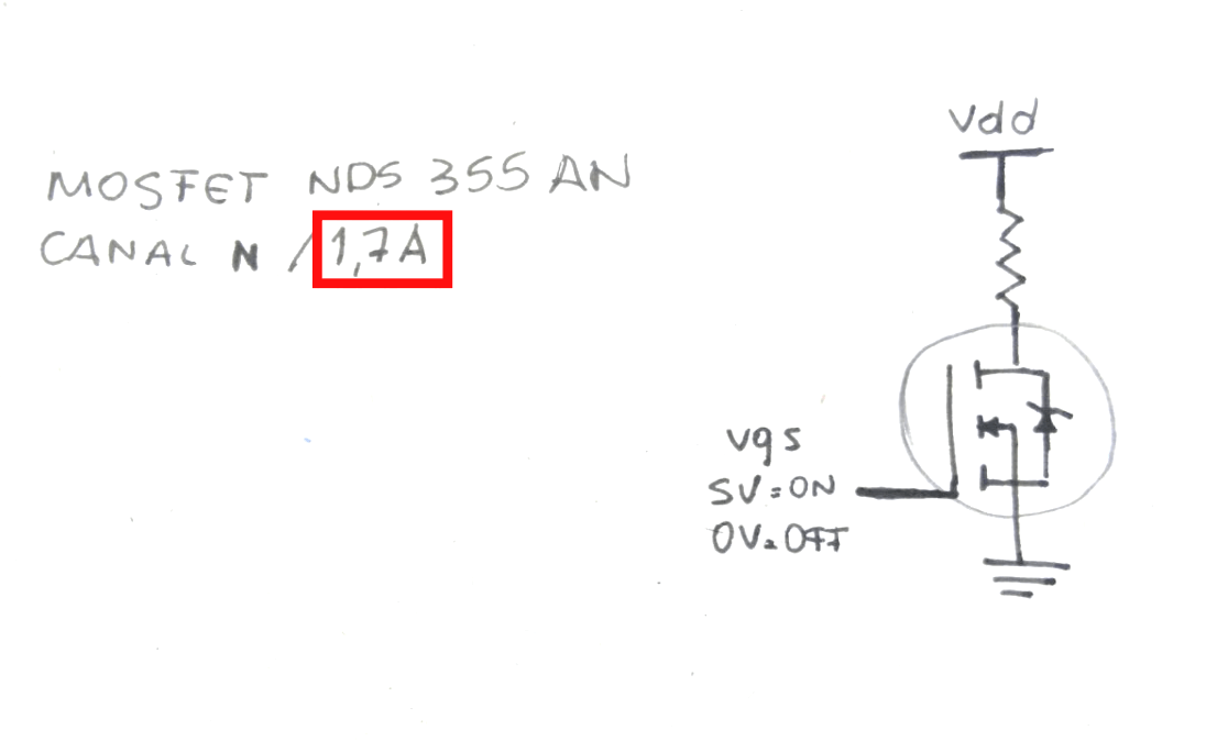
Used as guide the hello.RGB.45 board, but I redesigned it for use with a LED strip as output device. For this it was necessary to add MOSFETs for each LED color (red, green, blue) because i want to control the light power. To better understand how the Mosfet work and how to connect to a microcontroller, was a great help this page.
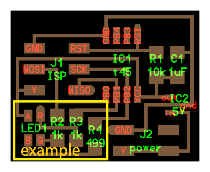
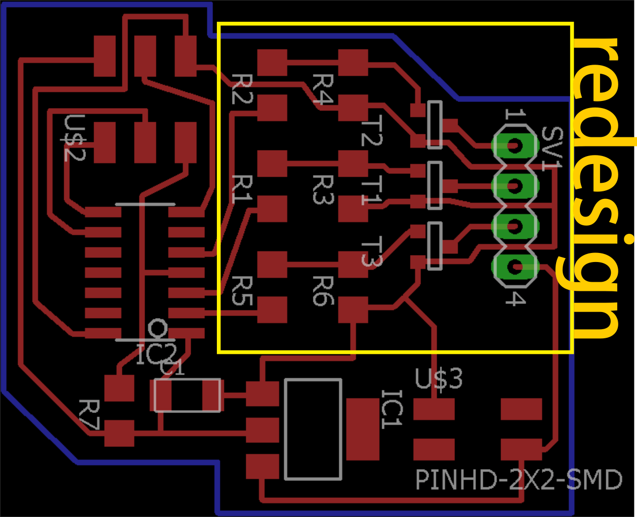
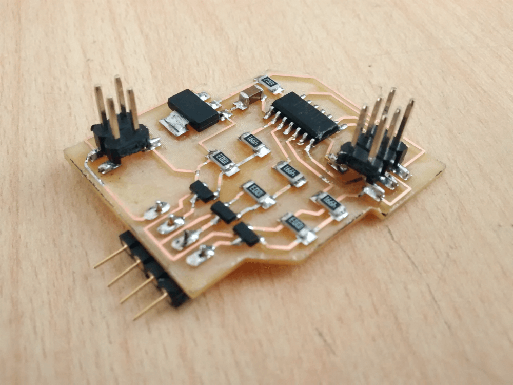
Designed the board in eagle and mechanized it in fab modules.
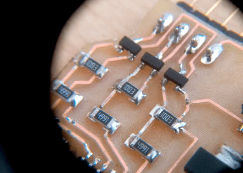
Before programming i made some calculations as voltage per length of the Led strip. The results were per 1 meter it needed 1,2 amperes. And the used mosfet is 1,7 amperes it supports up to 18 volts.
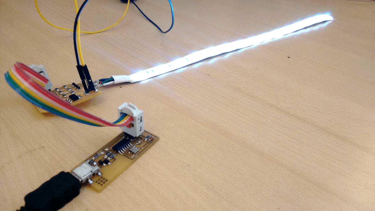
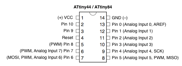
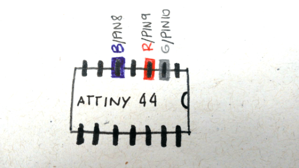
Also as used the Attiny44 microcontroller, i programmed through the FabISP in Arduino IDE. To define the different pins per each color of the LED strip i saw in the image to ATtiny Microcontroller Pin-Outs.
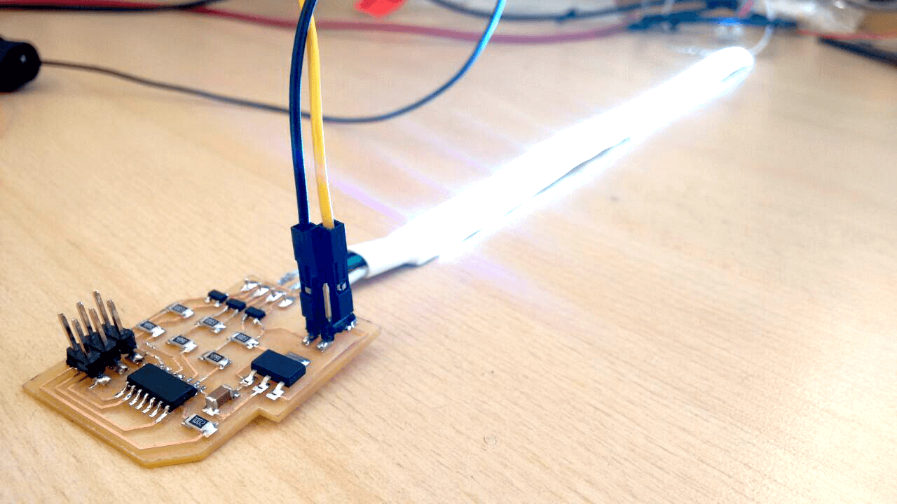
In this exercise i wanted regulate the withe light power. To obtain the white light, the RGB values should be the same, next you can see the generated code.
          //Defining Pins
#define REDPIN 9
#define GREENPIN 10
#define BLUEPIN 8

void setup() {
  // put your setup code here, to run once:
pinMode(REDPIN, OUTPUT);
pinMode(GREENPIN, OUTPUT);
pinMode(BLUEPIN, OUTPUT);
}

void loop() {

analogWrite(REDPIN, 255);
analogWrite(GREENPIN, 255);
analogWrite(BLUEPIN, 255);
delay(1500);

analogWrite(REDPIN, 130);
analogWrite(GREENPIN, 130);
analogWrite(BLUEPIN, 130);
delay(1500);

analogWrite(REDPIN, 60);
analogWrite(GREENPIN, 60);
analogWrite(BLUEPIN, 60);
delay(1500);

analogWrite(REDPIN, 15);
analogWrite(GREENPIN, 15);
analogWrite(BLUEPIN, 15);
delay(1500);

analogWrite(REDPIN, 5);
analogWrite(GREENPIN, 5);
analogWrite(BLUEPIN, 5);
delay(1500);
}