Testing & Results
Stepper Motor Testing: A3967 Driver board
The A3967 datasheet from Allegro describes the chip as a microstepping driver with translator. The IC is capable of driving bipolar stepper motors in full, half, quarter and eighth-step modes and output drive is limited to 30V and 750 mA. The chip also includes thermal shutdown and crossover-current protection.
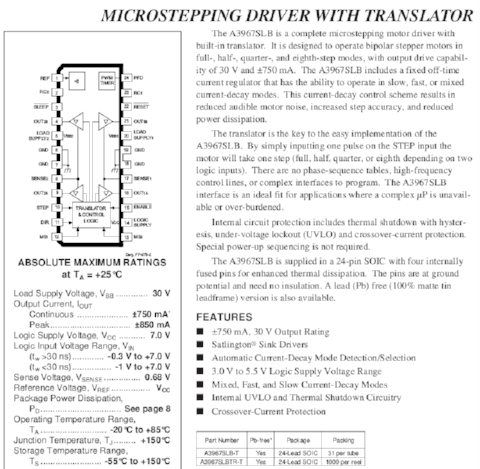
The amount of microstepping is controlled by the MS1 and MS2 inputs. MS1 and MS2 are both hard-wired to 5V, which puts the IC in eighth-step mode. The Enable input is active LOW. When /EN is HIGH, the driver outputs are disabled. The drive the motor, pulses are sent to the STEP input. Direction of rotation is controlled by the DIRECTION input pin.
The maximum current limit is set by the selection of Rs and Vref, with Itrip(max) = Vref/8Rs. Since I am using Vref = 1.854V (measured, adjustable via 10k potentiometer) and Rs = 0.5 ohm, this gives me a maximum trip current of 0.4635A.
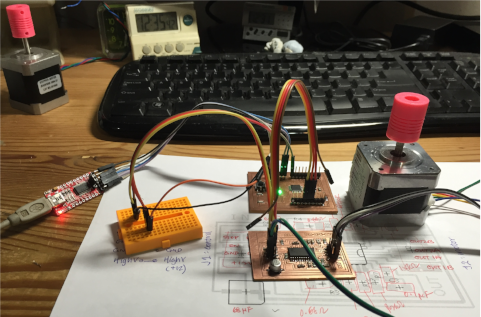
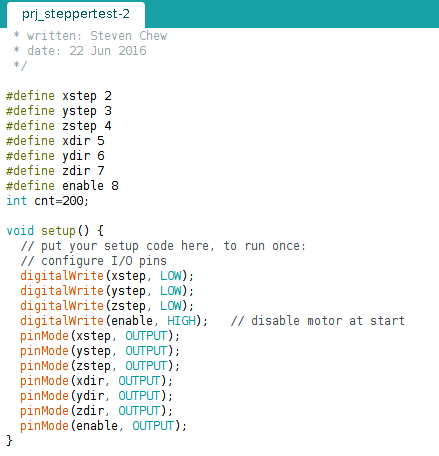
To test the A3967 stepper driver board, I wrote a simple program to continually drive the stepper motor in one direction, then in the opposite direction. The setup code for this program is displayed below:
/*
 * Testing A3967 Stepper Driver
 * w/Satshakit as controller
 * STEP - Pin 2
 * DIR  - Pin 5
 * /EN  - Pin 8
 *
 * Motor: 200 steps/rev
 *        1/8 microstepping
 * Gives: 1600 steps/rev
 *
 * written: Steven Chew
 * date: 21 Jun 2016
 */

#define xstep 2
#define xdir 5
#define enable 8
int cnt=200;

void setup() {
  // put your setup code here, to run once:
  // configure I/O pins
  digitalWrite(xstep, LOW);
  digitalWrite(enable, HIGH);   // disable motor at start
  pinMode(xstep, OUTPUT);
  pinMode(xdir, OUTPUT);
  pinMode(enable, OUTPUT);
}
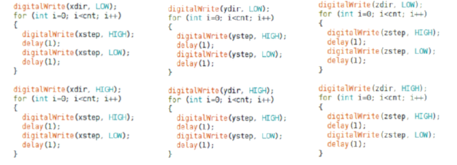
This is followed by the actual code to drive the stepper motor, placed within the loop() function:
  digitalWrite(enable, LOW);    // enable driver

  digitalWrite(xdir, LOW);
  for (int i=0; i<cnt; i++)
  {
    digitalWrite(xstep, HIGH);
    delay(1);
    digitalWrite(xstep, LOW);
    delay(1);
  }

  digitalWrite(xdir, HIGH);
  for (int i=0; i<cnt; i++)
  {
    digitalWrite(xstep, HIGH);
    delay(1);
    digitalWrite(xstep, LOW);
    delay(1);
  }

  digitalWrite(enable, HIGH);   //disable motor
A video showing the results of this simple test:
Stepper Motor Testing: 3-axis control using Grbl Shield
Once I managed to successfully drive a single stepper motor with my controller board and A3967 stepper module, my next challenge was to drive 3 motors, representing the X-, Y- and Z-axis. I decided to test this on the grbl shield instead of the A3967 module, as I wanted to verify the operation of this setup with the Polulu A4988 modules.
For this test, I decided to use the same pin configuration as the default grbl controller setup:

The program code is essentially the same as that for driving the single stepper motor. I initialized the controller pins for the step & direction for the 3-axes, then exercised each of the axis in turn by sending a pulse train to the respective stepper motor.
Programming Grbl Software to Controller Board
Since my CNC router not only had to be low-cost but also easy to use, I decided to use the opensource grbl control software for the gcode interpreter. Grbl is a highly optimized gcode parser and CNC controller that runs on the arduino platform.
There are 3 basic ways to program grbl into the microcontroller board:
- 1. Using the Windows-based XLoader application
- 2. Using an ISP programmer to upload pre-compiled grbl hex code
- 3. Compiling from grbl sourcecode on the arduino IDE
A quick grbl setup guide for Windows using Xloader can be viewed at the Protoneer blog site. The site also contains links to both XLoader and a pre-built hex version of Grbl.
The second approach, using an ISP programmer, is the usual standard way of programming any pre-compiled hex code to an avr device.
The third approach requires downloading the arduino sketch version of Grbl. The Grbl-Arduino library can be download from the Protoneer GitHub site. Once the Grbl-Arduino library has been downloaded, install it as an Arduino library in the usual way. Open the Grbl file from the Examples --> GRBL folder. Compile and upload the file to the arduino-based board.
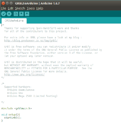
In practice, I found that all the 3 methods above worked with commercial arduino boards. However, when I tried to upload the grbl control software to my DIY arduino board, the board was no longer able to communicate via the FTDI serial interface. Compiling the grbl software from the Protoneer GRBL-Arduino library and uploading it to my DIY board worked like a peach and that was the method I used.
Installing Universal G-Code Sender
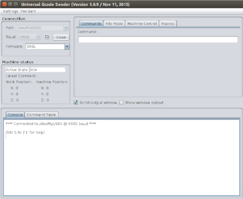
Universal-G-Code-Sender is a java-based, Grbl compatible cross-platform G-Code sender, available from William Winder's GitHub site. After downloading the software, unzip it to a directory. On a Linux system, you need to change the permission of start.sh to allow program execution.
Once the program has started, you need to connect to the Grbl control board. This is done by selecting the device port and baud rate, then clicking the Open button. On a Linux machine, the Port would be something like /dev/ttyUSB0. If everything is alright, you should see the message:
**** Connected to /dev/ttyUSB0 @ 9600 baud ****

Grbl 0.8c ['$' for help]
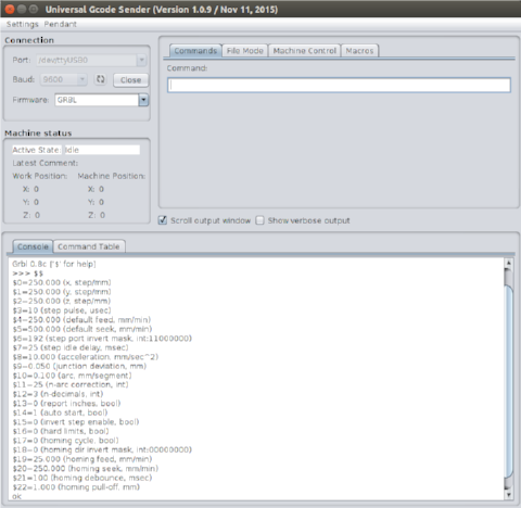
Typing $$ on the Command bar displays the current settings on the Grbl controller. These values can be changed by sending a new value for the corresponding parameter. For example, to change the Z-axis resolution to 1280 steps/rev:
$2 = 1600
The Machine Control tab displays a jog controller, where you can control the movement of the X-, Y- and Z-axis by clicking on the appropriate button. This screen also allows the user to set the work coordinate system (zero-points).

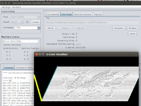
The File Mode tab allows the user to load a g-code file, visualize the cutpath before sending it to the Grbl controller. The middle mouse button shifts the workpiece in the visualizer. The right mouse button rotates it. Clicking the Send button will send the g-code to the CNC. The cutting process is displayed in the G-Code Visualizer window.
Calibration of CNC Machine
Before the CNC machine can be used, the X-, Y- and Z-axis has to be calibrated. The X- and Y-axis stepper motors came with integrated threaded screw rods and are from the MTM sets that we purchased for our fablab. I did not have the specifications for the threaded rods, but I recalled vaguely that Nadya mentioned something about the rods having 4 threads, instead of the typical single thread. Looking through the code for single_node.py from the MTM build, it seemed that the motors are 1.8 degree per step and the rods give 6.096mm/rev. Since I configured my stepper drivers for 1/8 microstepping mode, this gives:
    motor steps/rev = 200
    number of microsteps/step = 8
    thread pitch = 6.096 mm/rev
    effective step/mm = 200*8/6.096 = 262.47
Similar calculations for the Z-axis yields:
    motor steps/rev = 200
    number of microsteps/step = 8
    thread pitch = 2 mm/rev
    effective step/mm = 200*8/2 = 800
Using those values as a starting point, I configured my Grbl controller:
    $0 = 262.47
    $1 = 262.47
    $2 = 800
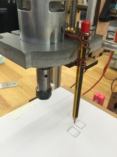
To perform the calibration test, I fixed a pencil to the Z-axis motor mount and a sheet of paper on the base plate, then used the Jog controls to draw 10mm lines in the X- and Y- directions. I also wrote a simple G-code program to draw a 10mm x 10mm square and sent it to the machine. I adjusted the values for steps/mm until I could draw a perfect square with the right dimensions.
Calibrating the Z-axis required a different approach, as I could not measure the movement of the pencil point accurately. I finally settled for making a mark on the linear support rod, then moving 10mm in the Z-direction and repeating the motion until I had the Z-axis calibrated.
To test the settings, I decided to import the g-code for one of the PCBs that I did earlier and draw it on the paper. The results were a bit of a letdown, as the pencil was not rigidly fixed onto the Z-axis mount and had a bit of free play.
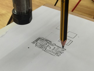
Video of the test PCB board layout drawing:
Results: Test Cut on Foam
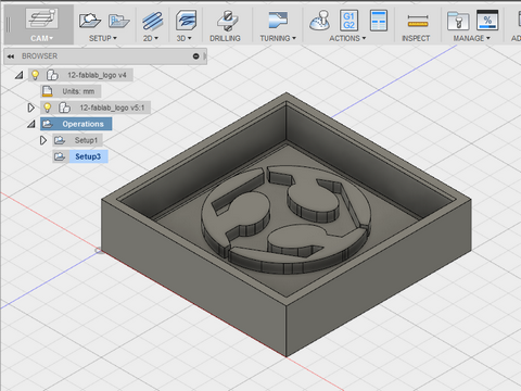
As can be seen from the test drawing above, my CNC router has not been fully calibrated yet. However, since I had a presentation coming up on 22 June, I decided to go ahead with a test cut on dense foam.
I had previously designed a simple part in Fusion 360 - a mold with the Fablab logo. I generated the CAM files for this part and simulated the milling operation, a face mill, followed by a pocket mill. Notice that I was unable to mill the smaller features on the model - I was using a 3mm flat-end mill, which I had on hand. Those features were < 3mm.
Video of the test PCB board layout drawing:
I then proceeded to load the gcode file in Universal G-code Sender and sent the job to my CNC machine. The surfacing operation went OK, but there are still some issues with the pocket milling operation. I've included a video of my whole design and build process, which I presented on 22 June.
Reflections
My final project implementation was only partially successful. The basic framework and mechanisms of my CNC worked. My Grbl controller board and stepper motor drivers worked well. The areas which needs improvements are the calibration of the mill. It is still not accurate enough yet. The Z-axis movement can also be improved. I used a single fixed mount for the spindle motor. In retrospect, I should have gone for thicker material, e.g. 12mm MDF for the X- and Z-axis mount, which would have given me a more rigid mount. I would also like to redesign the mount, so that it is more generic and can take different types and sizes of end effectors.
My Grbl control board is able to take limit switches mounted on the 3-axes, but these have not been implemented yet. Another area which I would like to improve upon is the test out my arduino shield compatible ATmega328 board. During the course of the project, I felt that I have been very careful when wiring my system. However, despite that, I stil managed to connect the wires wrongly on a few occasions.
My explorations on low-cost digital fabrication machines which can be made in a fablab will not end with this CNC router. I intend to do further work in this area and build up our expertise in building a range of different types of machines, such as CNC mill, router, PCB milling machine, 3D printers, laser cutters, 3D scanners, vinyl cutters and other machines useful for digital fabrication.
Downloads
The files and programs listed below were used in testing and calibrating my CNC. I've included links to some of the programs used, but am repeating them here for convenience: