Exercise 15 - Networking & Communications
Assignment
The assignment for this week is to:
- design & build a wired or wireless network
- connect at least 2 devices
Hello Bus - Design
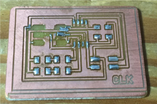
For my first network, I decided to build a hello.bus-based system, but with a small modification - adding another LED, so that I can still retain one LED to indicate data transmission and controlling the second LED over the network.
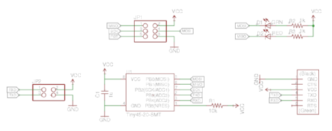
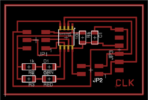
The Hello.Bus network comprises a bridge board, which connects to a computer via a FTDI connection, and node boards. My schematic and board layout for my bridge circuit are shown below:
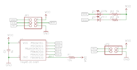
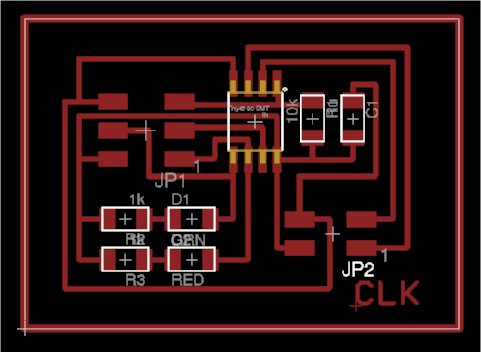
My schematic and board layout for my node modules are as follows:
Click on the links below to download the Eagle CAD files for my bridge and node boards:
- hello.bus.45.bridge schematic
- hello.bus.45.bridge layout
- hello.bus.45.node schematic
- hello.bus.45.node layout
Hello Bus - Programming
The same file is used for both the bridge and mode modules. My bridge board has node_id = 0; the 2 node boards have node_id = 1 and node_id = 2 respectively. I first tested my boards using Neil's sample program to test if I could communicate between the bridge and node modules.
I found that the bridge and node 1 board could talk to each other. I could not program my node 2 board at all. On troubleshooting, I found that some pins on my ISP connector were shorted. I increased the gap between the pads to make soldering more easy, but had widened it too much and this caused pins 3 and 5 of the ISP to be shorted by the copper left behind by my isolation milling process.
I tried to remove the ISP header by using a hot-air gun. I attempted to remove the plastic portion of my header, but ended up lifting the pads on my pcb - goodbye, hello board...
Fortunately, I had a spare bridge board, so I decided to use it as a node board instead - just leave the FTDI header out. Programming this board with node_id 2 went smoothly.
Another change that I made to Neil's sample code was to add in the pin definitions for my second LED:
  #define disp_pins PINB
    #define disp_pin (1 << PB1)
In the main program, I added code to initialise PortB as an output port and turn off my display LED:
  set(led_port, disp_pin);
    output(led_direction, disp_pin);
To toggle my display LED, I made use of a neat trick that is available for all AVR MCUs - you can toggle any of the digital IO pins by writing a logic 1 to the PINx register.
  if (chr == node_id){
    // toggle display led
    output(disp_pins, disp_pin);
    // rest of Neil's code
I reprogrammed my bridge and node boards with my modified code and tested them:
And here are some videos of my hello bus boards in action:
Click on the links below to download my files:
- C source for bridge and node boards
- Hex file for bridge board
- Hex file for node_id 1 board
- Hex file for node_id 2 board
SLIP Protocol
One of my reasons for doing the hello bus boards it because the same boards can be used for the SLIP protocol as well. I've been busy for the past few days, preparing to exhibit our Fablab at the InnovFest unBound 2016 event at Marina Bay Sands on 17 and 18 May and sharing the great things we are doing in the Fablab Network, Fab Foundation and Fablab Singapore Polytechnic with visitors to the conference and exhibition, so I haven't gotten around to writing code for and testing the SLIP protocol yet.

I've finally been able to get back to working on my documentation for the SLIP or Serial Line Internet Protocol. According to the Wikipedia article, SLIP is an encapsulation of the IP protocol, designed to work over serial ports and modem connections. SLIP has been largely replaced by the PPP protocol, which does not require IP address configuration to be set before it (connection) is established. However, on mocrocontrollers, SLIP is still the preferred way of encapsulating IP packets, which basically means that it is still actively used for this purpose.
From what I've read, SLIP modifies a standard TCP/IP datagram by:
- appending a special "END" byte (0xC0) to it, which distinguishes datagram boundaries
- if the END byte occurs in the data to be sent, the 2 byte sequence ESC (0xDB), ESC_END (0xDC) is sent instead
- if the ESC byte occurs in the data, the 2 byte sequence ESC, ESC_ESC (0xDD) is sent
- variants of the protocol may begin, as well as end packets with END
For this test, I reused the same 3 boards, which I used in the Hello Bus implementation, with the same physical connection. Only the software has been changed. A look at Neil's code for implementing the SLIP protocol on the Hello Bus boards show the definition of the END, ESC, ESC_END and ESC_ESC characters.
#define END 192 // packet end
#define ESC 219 // escape char
#define ESC_END 220 // end escape
#define ESC_ESC 221 // escape escape
The IP address and port numbers for read and write operations for the bridge or node boards are defined in ADDRESS_0 through ADDRESS_3:
#define ADDRESS_0 10
#define ADDRESS_1 0
#define ADDRESS_2 0
#define ADDRESS_3 2

#define WRITE_PORT 1234
#define READ_PORT 1235
I modified the code here such that my bridge board had IP address 10.0.0.2 and the node boards 10.0.0.3 and 10.0.0.4.
The offset (location) of the source and destination IP address and ports within the IP datagram is declared here:
#define SOURCE_ADDRESS 12
#define DEST_ADDRESS 16
#define SOURCE_PORT 20
#define DEST_PORT 22
#define PAYLOAD 28
The C-routines for reading or writing a single character or string of characters uses bit-banging on pins PB3 (RXD) and PB4 (TXD), similar to the FTDI implementation on ATtiny44 or ATtiny45 boards in earlier assignments.
The routine to read a packet from the serial bus reads each incoming character and checks if it is the special "END" character. If yes, the IP packet is complete, otherwise the character is appended to the incoming data buffer.
unsigned char get_packet(unsigned char *buf) {
   //
   // get SLIP packet
   //
   static unsigned char chr, ptr;
   ptr = 0;
   while (1) {
      get_char(&serial_pins, serial_pin_in, &chr);
      switch(chr) {
         case END:
            return ptr;
         case ESC:
            get_char(&serial_pins, serial_pin_in, &chr);
            switch(chr) {
               case ESC_END:
                  chr = END;
                  break;
               case ESC_ESC:
                  chr = ESC;
                  break;
               }
         default:
            if (ptr < MAX_PACKET)
               buf[ptr++] = chr;
            else
               return 0;
         }
      }
   }
A similar routine is used to transmit IP packets onto the serial bus.
The IP packet is created in the assemble_packet() routine. Looking at the sourcecode, one can easily see that the fields in the IP and UDP headers are crafted here.
unsigned char assemble_packet(unsigned char *buf,
   unsigned char source_address_0,
   unsigned char source_address_1,
   unsigned char source_address_2,
   unsigned char source_address_3,
   unsigned char dest_address_0,
   unsigned char dest_address_1,
   unsigned char dest_address_2,
   unsigned char dest_address_3,
   unsigned char source_port_0,
   unsigned char source_port_1,
   unsigned char dest_port_0,
   unsigned char dest_port_1,
   unsigned char *payload,
   unsigned char payload_length) {
   //
   // assemble packet
   //
   unsigned char i;
   //
   // IP
   //
   buf[0] = 0x45; // version = 4, header length = 5 32-bit words
   buf[1] = 0; // type of service
   buf[2] = 0; // packet length high byte
   buf[3] = 28 + payload_length; // packet length low byte
   buf[4] = 0; // identification high byte
   buf[5] = 0; // identification low byte
   buf[6] = 0; // flag, fragment offset high byte
   buf[7] = 0; // flag, fragment offset low byte
   buf[8] = 255; // time to live
   buf[9] = 17; // protocol = 17 for UDP
   buf[10] = 0; // header checksum (to be calculated)
   buf[11] = 0; // header checksum (to be calculated)
   buf[12] = source_address_0; // source address byte 1
   buf[13] = source_address_1; // source address byte 2
   buf[14] = source_address_2; // source address byte 3
   buf[15] = source_address_3; // source address byte 4
   buf[16] = dest_address_0; // dest address byte 1
   buf[17] = dest_address_1; // dest address byte 2
   buf[18] = dest_address_2; // dest address byte 3
   buf[19] = dest_address_3; // dest address byte 4
   //
   // UDP
   //
   buf[20] = source_port_0; // source port high byte
   buf[21] = source_port_1; // source port low byte
   buf[22] = dest_port_0; // dest port high byte
   buf[23] = dest_port_1; // dest port low byte
   buf[24] = 0; // payload length high byte
   buf[25] = payload_length; // payload length low byte
   buf[26] = 0; // payload checksum (not used)
   buf[27] = 0; // payload checksum (not used)
   //
   // payload
   //
   for (i = 0; i < payload_length; ++i)
      buf[28+i] = payload[i];
Incoming IP datagrams are handled by the process_packet() function, where the program checks if the destination IP address matches the IP address of the node. If there is a match, the routine further checks the payload to see if it should turn the on-board LED on or off. This function ends by calling assemble_packet() to create the packet, followed by put_packet() to send the IP packet out via the serial bus.
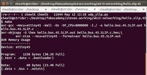
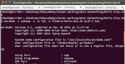
I modified the IP address in Neil's hello.bus.45.SLIP.c program for my bridge and each of my node boards, then ran make to generate the corresponding hex file. I then used avrdude to upload the hex file to my boards.
- 1. Bridge board --> 10.0.0.2
- 2. Node 1 --> 10.0.0.3
- 3. Node 2 --> 10.0.0.4
Once all the boards were programmed, I connected them via the serial bus and connected my FTDI module to the bridge board. To test the program, I ran the python module:
On Windows:
        python udp_slip.py COM6 9600

    On Linux:
        python udp_slip.py /dev/ttyUSB0 9600

    On OSX:
        python udp_slip.py /dev/tty.usbserial-A50285BI
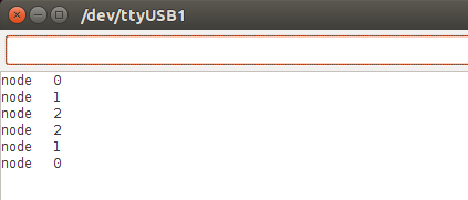
From the resultant program window, I entered the IP address, followed by "on" or "off", then clicked the "send outgoing packet" button to send the IP packet to the tiny45 boards.
I've placed a copy of the SLIP and python program from Neil's lecture here for the viewer's convenience. Please refer to Neil's lecture for more details.