Exercise 13 - Output Devices
Assignment
The assignment for this week is to:
- add an output device to a microcontroller board that you've designed
- program it to do something
- can be a new board or addition to an existing board
RGB Led
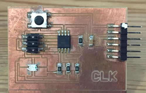
For my first output device, I've decided to design an ATtiny45 board with RGB led and pushbutton switch. This is a very useful circuit and can easily be turned into a mood lamp project. The pushbutton switch can be used to change the mode of operation of the RGB led, for example to cycle through a selection of fixed colors or to automatically cycle through a range of colors.
I have previously made such a board during our Input Devices week, and I decided to program the RGB led on this board for a start. Displaying individual colors or fixed colors is very trivial. The challenge is to be able to cycle through the colors such that the change from one color to another is smooth.
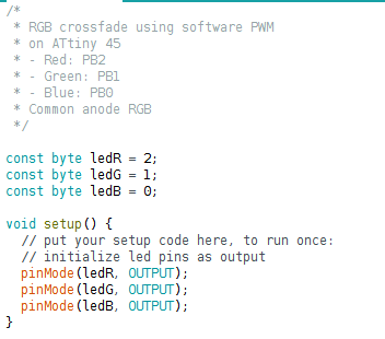
Since the ATtiny45 has limited (2 channels) hardware pwm, I decide to utilize a software PWM for my board instead. My first attempt was to have a single running counter and use this to generate 3 separate software pwms, one for each of the R, G, and B leds. I also wanted to offset each LED by 120 deg (out of a 360 deg cycle). The program quickly became somewhat confusing and the transition from one color to another wasn't smooth.
I abandoned that approach and decided to adopt a simpler approach, where I would transition through the color wheel from Red to Yellow (Red + Green), then to Green, followed by Cyan (Green + Blue), all the way back to Red. I used the following article from Instructables as a guide: Attiny-RGB-Mood-Light
RGB Led - Code
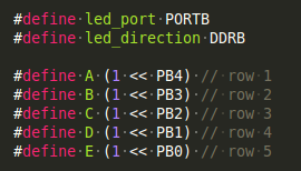
I first defined the pins for the Red, Green and Blue led and set these bits to output.
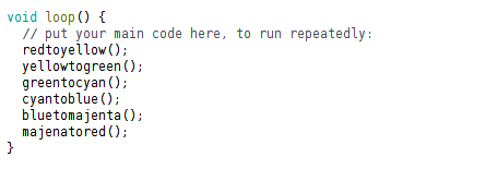
The main program loop cycles through the different color combinations:
- from red to yellow
- from yellow to green
- from green to cyan
- from cyan to blue
- from blue to magenta
- from magenta back to red
Each of the functions starts with a beginning color, then slowly fades from that color to the next color. For example, the redtoyellow() routine starts with the Red led turned on, then fades the Red component and turns up the Green color by varying the duty cycle for each color. The rest of the functions use a similar technique.
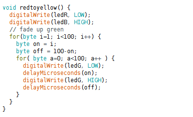
The program code can be downloaded here.
A video of the board cycling through the various colors:
I also decided to redesign my RGB led board and the Eagle files for my new board are found below.
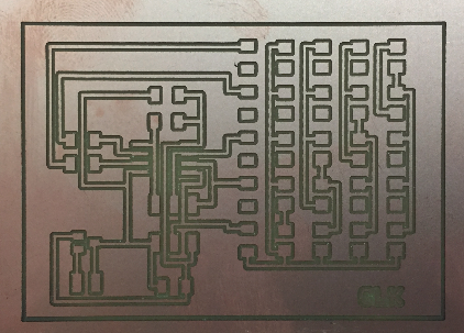
LED Array Using Charlieplexing
Charlieplexing allows one to drive many LEDs using the fewest possible number of I/O pins. Neil's LED array board looks quite neat, but uses an ATtiny44. I decided to redesign the board using an ATtiny45 instead of the Tiny44. Since I intend to drive 5x4 = 20 LEDs, I will be using all 5 available I/O lines on the Tiny45, leaving just the Reset pin unused for my application. This allows me to continue using the ISP header to reprogram my board.
The Eagle files for my board can be downloaded using the links below.
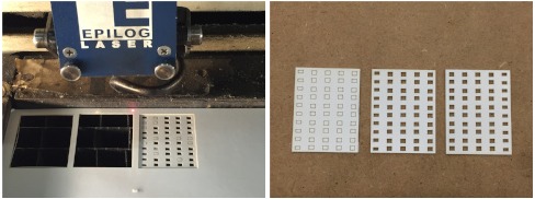
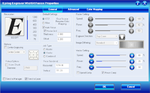
To create the mask for my led array, I exported a png file from my board layout and edited it in Photoshop to remove the unwanted section and the pcb traces, leaving only the pads for the pull-up resistors and leds. From the resultant image, I imported it into CorelDraw and used our Epilog laser cutter to cut out the pad area for those components. My settings for the laser cutter:
- Speed: 80%
- Power: 20%
- Frequency: 50%
- No of passes: 2
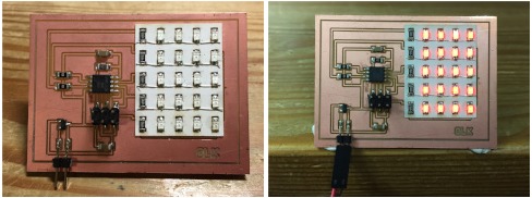
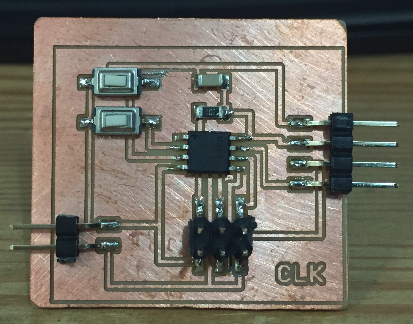
My charlieplexed LED board, fully stuffed:
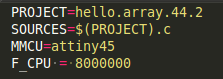
To program the board, I used Neil's demo program as a starting point and modified it for my specific pin configuration and the ATtiny45 processor:
Learning Points
I made a number of mistakes in the process of stuffing and programming my Tiny45 charlieplexed board:
- Soldered the current limiting resistors & leds before making the cardboard mask - after laser cutting the mask, I realised that it should have gone on before the resistors and leds!
- The hot-air gun and 1206 leds don't go well together - in desoldering the leds, the plastic lens on one of the leds fell apart and a number of leds were damaged (which I didn't realise at that time)
- I should have tested each led individually before resoldering it - I found out that some of the leds were damaged after soldering them in, which meant more hot-air and desoldering
- I should have soldered the common wire to the pads first before the leds - I soldered & tested the leds first, before the wire. In the process of soldering the wires, some more leds were damaged
Files for this exercise:
OLED
One of Neil's demo boards uses a Tiny44 to drive an LCD display. I decided to design a board which is able to drive an I2C-based OLED display, as this gives me much greater flexibility in the kind of things (text, graphics) that I can display. Learning how to drive an OLED will come in very handy when I design the display for the telemetry system on our solar car.
I was also inspired by an Instructables article that I came across: ATtiny Watch Core, which uses a Tiny85 interfaced to an OLED as a digital watch.
The first thing that I tried was to drive the OLED using the OLED library on an Arduino Uno board, using the Adafruit OLED library. The video shows how flexible an OLED display can be:
ATmega328 SPduino
My final project is a low cost CNC milling machine. There are 2 possible approaches that I am considering:
- Using gestalt nodes
- Using arduino board running gbrl, with RAMPs shield
I've looked at previous 'Duino clones designed by Fab Academy students. All of these clones do not follow the standard Arduino pinout and therefore cannot be used with existing Arduino shields. Since one possible approach for my final project is to make use of common Pololu RAMPS 1.4 shield that is compatible with the an Arduino board, I have decided to design my own Atmega328-based 'Duino clone that uses standard Arduino pinout. This makes it compatible with existing Arduino shields available in the market.
I'm still designing my board and will update it as it progresses.