Final Project Development - The Process
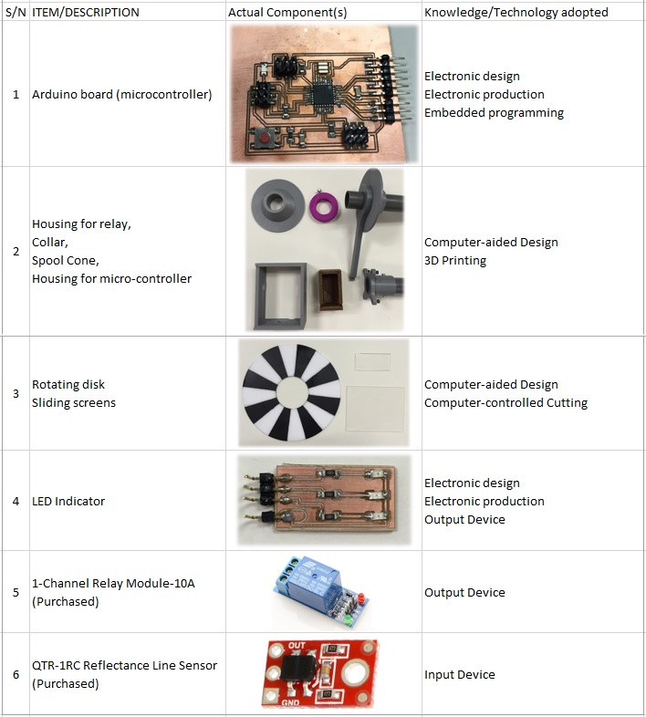
The following table shows the components/parts done and purchased and the technologies involved in doing it.
Electronic Design
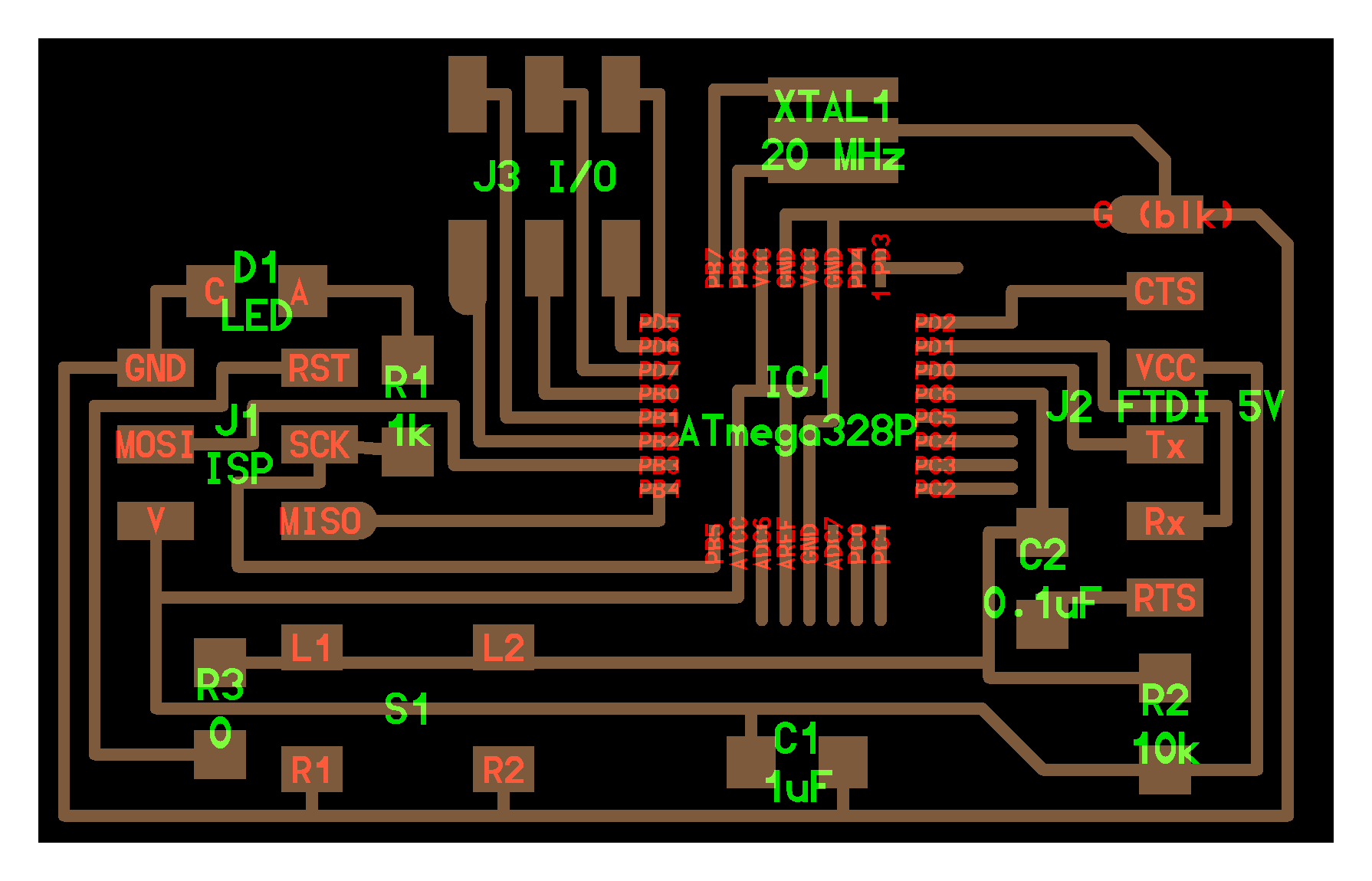
The microcontroller is the brain of the system. It needs to read input from the line sensor and give command to the relay and LED indicator to cut-off power and blink to alert operator respectively.
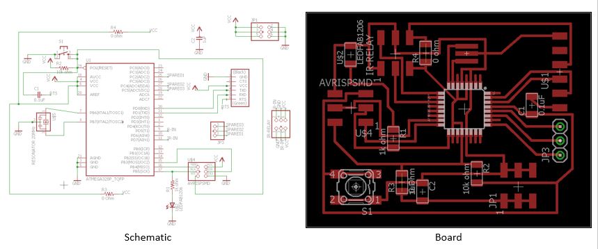
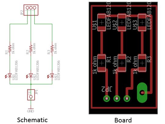
With reference to the notes taken on the number of pins needed for relay, line sensor, and LED indicator (self decide on no. of LED used). The following electronic schematic and board is generated. N.B. This board is taking reference from hello.arduino.328P and being modified accordingly.
Programming
After stuffing all the components onto the milled pcb boards, arduino bootloader was burnt into the micro-controller chip. Prior to burning, add the following URL into Arduino IDE Boards Manager under "File>Preferences".
https://adafruit.github.io/arduino-board-index/package_adafruit_index.json,https://raw.githubusercontent.com/damellis/attiny/ide-1.6.x-boards-manager/package_damellis_attiny_index.json,https://raw.githubusercontent.com/sleemanj/optiboot/master/dists/package_gogo_diy_atmega8_series_index.json
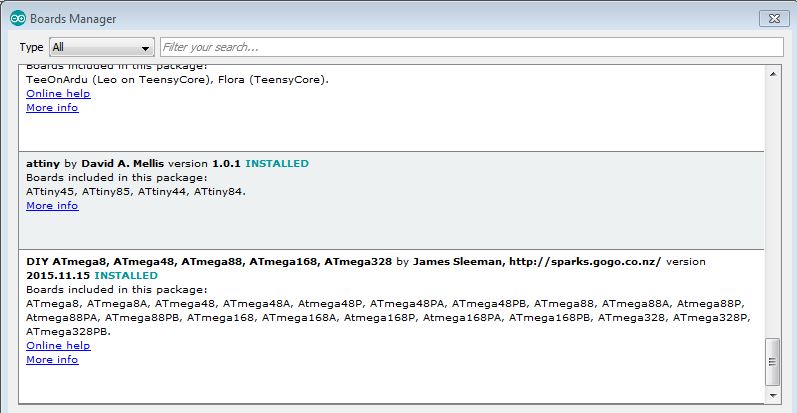
Go to board manager under "Tools>Board:>Boards Manager..." to install the DIY ATmega328 board managers. The following shows the successful installation.
Next step is to include the reflectance line sensor library into Arduino IDE libraries. Download this link, unzipped the folder and place it at Arduino's libraries in local C:\ drive.
The following was writen in the sketch and upload into the ATmega328 chip.
void setup()
{
  Serial.begin(9600);
  delay(1000);
  pinMode(A2, OUTPUT);
  pinMode(A4, OUTPUT);
  pinMode(A5, OUTPUT);
  pinMode(5, OUTPUT);
}
void loop()
{
  qtrrc.read(sensorValues);
  int a=0, b=0;
  unsigned char i;
    while (sensorValues[i] < 700)
    {
       qtrrc.read(sensorValues);
       a++;
       delay (100);
       Serial.println(sensorValues[i]);
       //if(a == 1800)
       if(a == 100)
         digitalWrite(5, HIGH);
       while (a>=100)
       {
            digitalWrite(A2, HIGH);
            digitalWrite(A4, HIGH);
            digitalWrite(A5, HIGH);
            delay(500);
            digitalWrite(A2, LOW);
            digitalWrite(A4, LOW);
            digitalWrite(A5, LOW);
            delay(500);
       }
    }
    while (sensorValues[i] >= 700)
    {
       qtrrc.read(sensorValues);
       b++;
       delay (100);
       Serial.println(sensorValues[i]);
         //if(b == 1800)
         if(b == 100)
           digitalWrite(5, HIGH);
        while (b>=100)
       {
            digitalWrite(A2, HIGH);
            digitalWrite(A4, HIGH);
            digitalWrite(A5, HIGH);
            delay(500);
            digitalWrite(A2, LOW);
            digitalWrite(A4, LOW);
            digitalWrite(A5, LOW);
            delay(500);
       }
    }
  Serial.println(" ");
  delay(100);
}
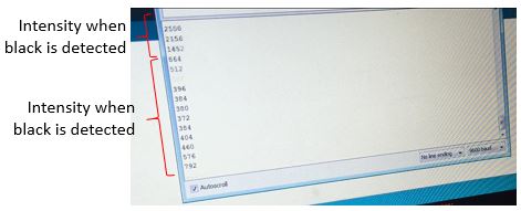
The intensity of the line sensor was set based on black and white surface, black as non-reflective surface and white as reflective surface. From the Arduino serial monitor, the intensity read 700 and above for black surface and 700 and below for white surface. These readings varies with the distance of the sensor to the surface. The manufacturer recommended sensing distance is 0.375".
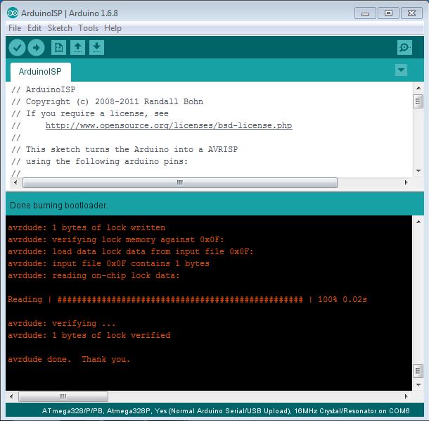
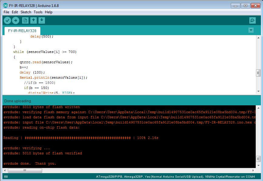
Upload the sketch into the ATmega328 chip. The following shows the successful loading.
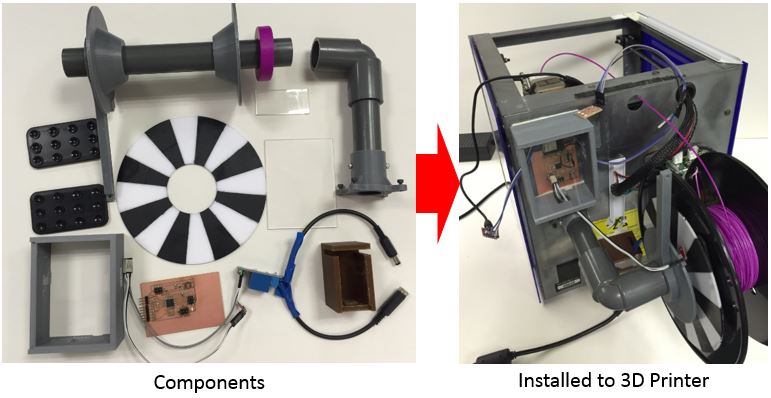
Next is to assemble and install all the components into the 3D printer.
Refer to this for the system in action.