Week 15 - Networking and Communications
Task:
To build a wired &/or wireless network connecting at least two processors.
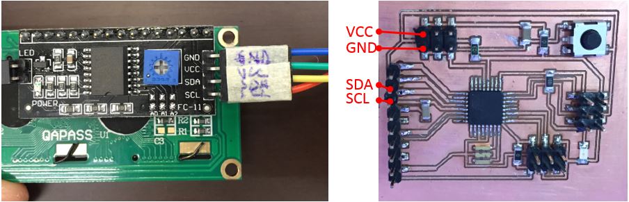
In this task, I2C communication will be used as demonstration. This task will use an LCD with I2C module and micro-controller with chip ATmega328P built in the previous week. ATmega328P will be the master and the I2C chip within the module will be the slave.
Prior to this, the address of the LCD needs to be identified. How? The following program written by Nick Gammon was adopted. Click the link to read more.
#include <Wire.h>

void setup() {
Serial.begin (9600);

while (!Serial)
{
}

Serial.println ();
Serial.println ("I2C scanner. Scanning ...");
byte count = 0;

Wire.begin();
for (byte i = 8; i < 120; i++)
{
Wire.beginTransmission (i);
if (Wire.endTransmission () == 0)
{
Serial.print ("Found address: ");
Serial.print ("DEC");
Serial.print (i, DEC);
Serial.print (" (0x");
Serial.print (i, HEX);
Serial.println (")");
count++;
delay (1);
} // end of good response
} // end of for loop
Serial.println ("Done.");
Serial.print ("Found ");
Serial.print (count, DEC);
Serial.println (" device(s).");
} // end of setup

void loop() {}
Upload the above program into the micro-controller ATmega328P and run the Arduino serial monitor when done (with LCD I2C module attached to the micro-controller). The wire connection shall be
| GND | GND |
| Vcc | Vcc |
| A4 | SDA |
| A5 | SCL |
Activate the serial monitor and the address shall appear as the following.
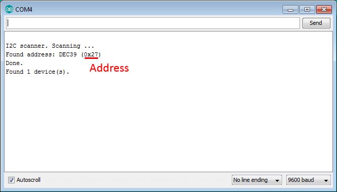
Once the address is found, it shall be included in the program. The next task is to program the master (ATmega328P) to display "I SURVIVED!" moving right and left and display "AWESOME!" in the next row.
The following program is written and uploaded into the microcontroller.
#include <Wire.h>
#include <LCD.h>
#include <LiquidCrystal_I2C.h>

#define I2C_ADDR    0x27  // Define I2C Address where the PCF8574T is
#define BACKLIGHT_PIN     3
#define En_pin  2
#define Rw_pin  1
#define Rs_pin  0
#define D4_pin  4
#define D5_pin  5
#define D6_pin  6
#define D7_pin  7

int n = 1;

LiquidCrystal_I2C  lcd(I2C_ADDR,En_pin,Rw_pin,Rs_pin,D4_pin,D5_pin,D6_pin,D7_pin);

void setup()
{
  lcd.begin (16,2);  // initialize the lcd
  lcd.setBacklightPin(BACKLIGHT_PIN,POSITIVE);
  lcd.setBacklight(HIGH);
  lcd.home ();
}

void loop()
{

// Reset the display
  lcd.clear();
  delay(1000);
  lcd.home();

// Print on the LCD
  lcd.backlight();
  lcd.setCursor(0,0);
  lcd.print("I SURVIVED!");
  delay(1000);

  for (int i=0;i < 6; i++) //scroll the text 8 positions to the right
  {
  lcd.scrollDisplayRight();
  delay(200);
  }
  for (int i=0;i < 6; i++) //scroll to the left
  {
  lcd.scrollDisplayLeft();
  delay(200);
  }
  lcd.setCursor(8,1);
  lcd.print("AWESOME!");
  delay(2000);
}
The micro-controller and the LCD module are powered up with FTDI. The following shows the set-up and the outcome of the integration.
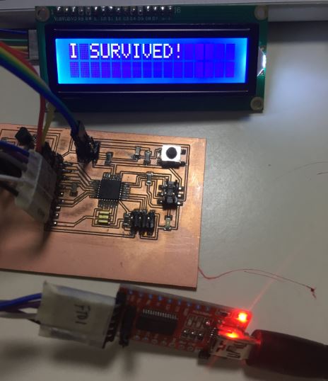
The working files can be downloaded here.
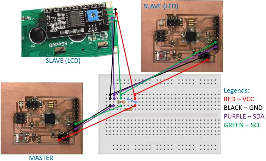
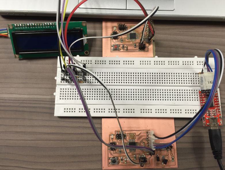
To further experiment the I2C communication, the following steps will demonstrate I2C 1 master (diy micro-controller with ATMega328P chip[master]) to control 2 slaves (another diy micro-controller[slave] with ATMega328P chip and I2C LCD Module).
What it does?
Using serial monitor within Arduino IDE as input, the master will command 1 slave to turn on/off its on board LED and another slave to display on the LCD.
In thic demo, the following will be the input to serial monitor
The following is written as MASTER and uploaded into the Master micro-controller.
#include <Wire.h>
#include <LCD.h>
#include <LiquidCrystal_I2C.h>

#define I2C_ADDR    0x27  // Define I2C Address where the PCF8574A is
#define BACKLIGHT_PIN     3
#define En_pin  2
#define Rw_pin  1
#define Rs_pin  0
#define D4_pin  4
#define D5_pin  5
#define D6_pin  6
#define D7_pin  7

int n = 1;

LiquidCrystal_I2C  lcd(I2C_ADDR,En_pin,Rw_pin,Rs_pin,D4_pin,D5_pin,D6_pin,D7_pin);


void setup()
{
  Serial.begin(9600);
  Wire.begin(5);
  Serial.println("'a' - diplay & ON LED");
  Serial.println("'s' - OFF LED & good bye");

  lcd.begin (16,2);  // initialize the lcd
  lcd.setBacklightPin(BACKLIGHT_PIN,POSITIVE);
  lcd.setBacklight(HIGH);
  lcd.home ();
}

void loop()
{
  while(Serial.available())
  {
    char c = Serial.read();

    if (c == 'a')
    {
      Wire.beginTransmission(5);
      Wire.write('a');
      Wire.endTransmission();

      // Reset the display
      lcd.clear();
      delay(1000);
      lcd.home();

      // Print on the LCD
      lcd.backlight();
      lcd.setCursor(0,0);
      lcd.print("I SURVIVED!");
      delay(1000);

      for (int i=0;i < 6; i++) //scroll the text 10 positions to the right
      {
      	lcd.scrollDisplayRight();
      	delay(200);
      }
      for (int i=0;i < 6; i++) //scroll to the left
      {
      	lcd.scrollDisplayLeft();
      	delay(200);
      }
      lcd.setCursor(8,1);
      lcd.print("AWESOME!");
      delay(2000);
    }
    else if (c == 's')
    {
      Wire.beginTransmission(5);
      Wire.write('s');
      Wire.endTransmission();

      lcd.clear();
      delay(1000);
      lcd.home();

      lcd.backlight();
      lcd.setCursor(4,0);
      lcd.print("GOOD BYE");
      lcd.setCursor(0,1);
      lcd.print("****************");
      delay(1000);
    }
  }
}
The following is written as SLAVE and uploaded into the Slave micro-controller.
#include <Wire.h>

void setup()
{
  Wire.begin(5);
  Wire.onReceive(receiveEvent);

  pinMode(13, OUTPUT);
  digitalWrite(13, LOW);
}

void loop()
{
}

void receiveEvent(int howMany)
{
  while(Wire.available())
  {
    char c = Wire.read();

    if(c == 'a')
    {
      digitalWrite(13,HIGH);
    }
    else if(c == 's')
    {
      digitalWrite(13,LOW);
    }
  }
}
2 resistors (value 4.3k Ohm each) will be needed as pull-up resistor for this setup. The resistors are used to restore the signal to high when no device is asserting it low. Click link to read up more about pull up resistors in I2C.
The followings show the hardware connection for this setup.
Here is the result.