Week 13 - Output Devices
Tasks:
To add an output device to a microcontroller board designed and program it to do something
Micro-controller
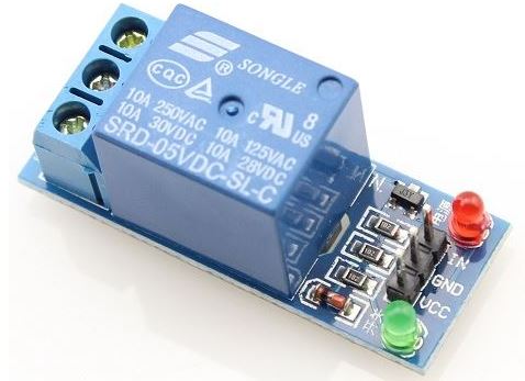
The micro-controller for Output Devices is the same as Input Devices. The relay module has 3 pins too ie. IN, GND, and Vcc. In ATmega328, IN is connected to pin PD5. Eventually, the relay will use in final project, ie. to cut-off power supply to 3D printer.
Programming
The following program is written into the Arduino sketch and uploaded into the micro-controller.
	#include <SoftwareSerial.h>
	int Relay = 5;

	void setup()
	{
  	pinMode(13, OUTPUT);        //Set Pin13 as ATmega328's LED Output
  	digitalWrite(13, HIGH);     //Set Pin13 High
  	pinMode(Relay, OUTPUT);     //Set Pin5 as relay output
	}
	void loop()
	{
          digitalWrite(Relay, HIGH);   //Turn off relay
          delay(5000);
          digitalWrite(Relay, LOW);    //Turn on relay
          delay(5000);
	}
Measurement
The following shows the result:
Small DC Motor as Output with Speed Input through Serial Monitor
The following are the components needed to perform this task.
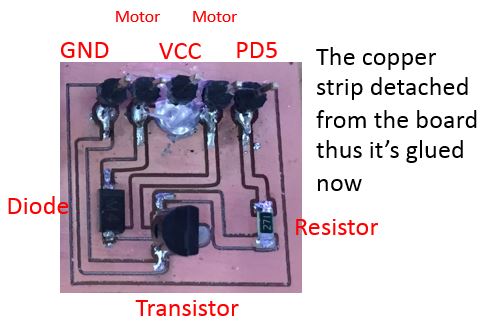
Referring closely to "learn.adafruit.com", additional board to control the motor (see the following) is designed and milled.
Programming
The following program is written into the Arduino sketch and uploaded into the micro-controller through FTDI.
	#include <SoftwareSerial.h>
	int motorPin = 5;

     void setup()
     {
      pinMode(motorPin, OUTPUT);
      Serial.begin(9600);
      while (! Serial);
      Serial.println("Speed 0 to 255"); // number increases with speed
     }

     void loop()
     {
     if (Serial.available())
     {
      int speed = Serial.parseInt();
      if (speed >= 0 && speed <= 255)
     {
       analogWrite(motorPin, speed);
       }
      }
     }
The Result
The working files can be downloaded here.
DC-motor board and
DC-motor schematic