Week 11 - Input Devices
Tasks:
To measure something: add a sensor to a micro-controller board and read it.
Micro-controller
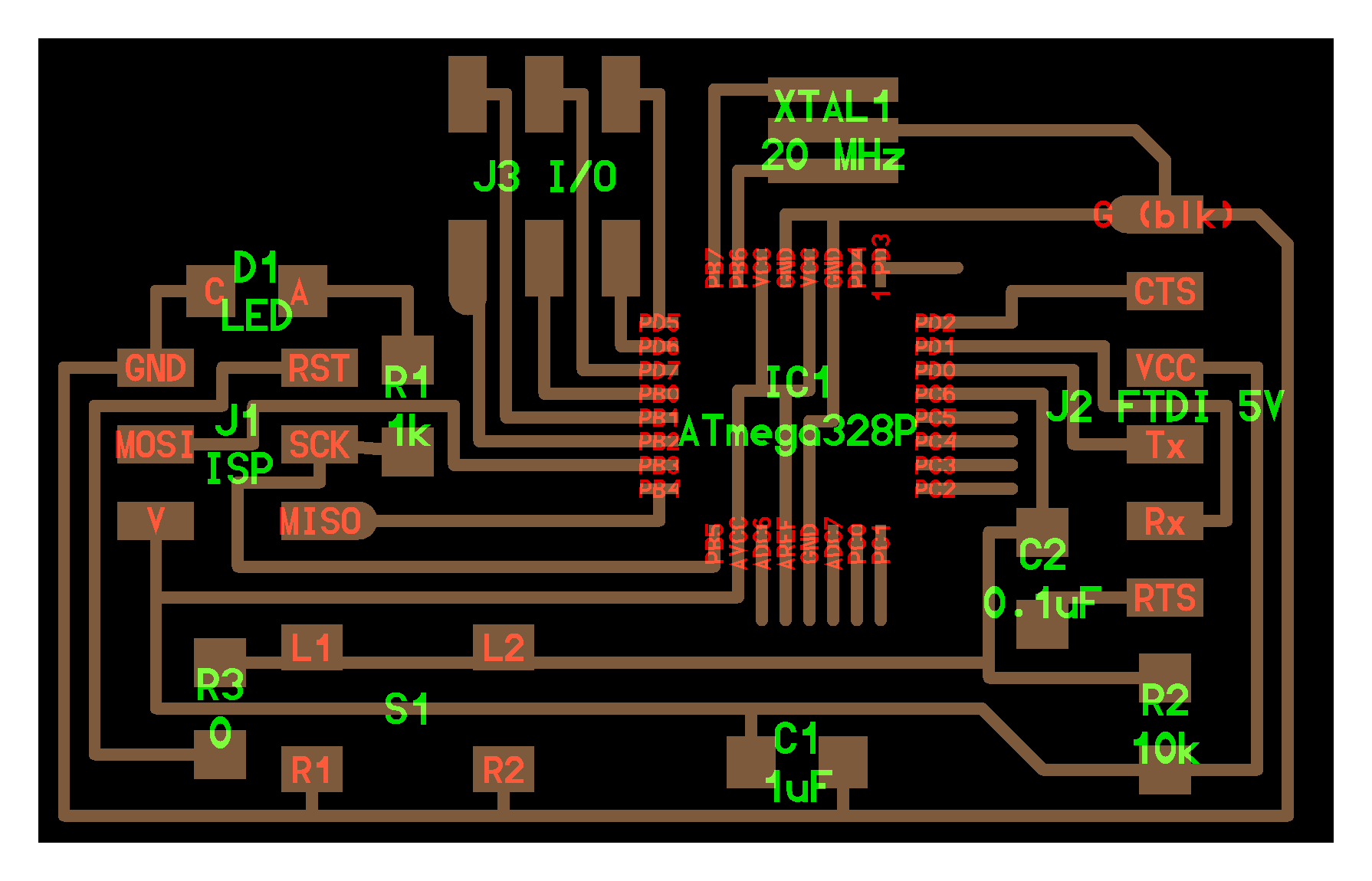
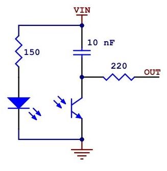
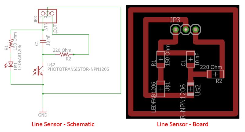
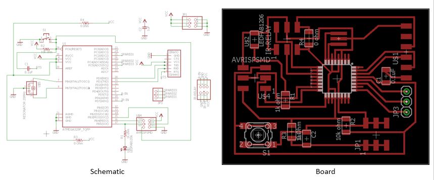
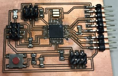
The design of this micro-controller will be used in the final project. The board design is modified from hello.arduino.328P. The line sensor was recycled from last 2 year project. It has 3 pins ie. GND, Vin and OUT. In ATmega328, OUT is connected to pin PD7. To show that the line sensor can also be diy-ed, the following schematic and board layout is provided.
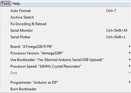
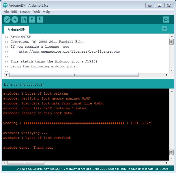
Next, mills the board and stuffs all the components, arduino bootloader was then burnt into the micro-controller chip. Prior to burning, add the following URL into Arduino IDE Boards Manager under "File>Preferences".
https://adafruit.github.io/arduino-board-index/package_adafruit_index.json,https://raw.githubusercontent.com/damellis/attiny/ide-1.6.x-boards-manager/package_damellis_attiny_index.json,https://raw.githubusercontent.com/sleemanj/optiboot/master/dists/package_gogo_diy_atmega8_series_index.json
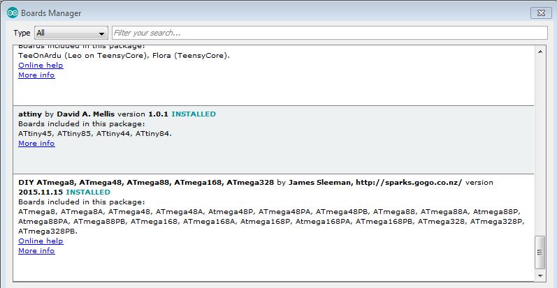
Go to board manager under "Tools>Board:>Boards Manager..." to install the DIY ATmega328 board managers. The following shows the successful installation.
Next step is to include the reflectance line sensor library into Arduino IDE libraries. Download this link, unzipped the folder and place it at Arduino's libraries in local C:\ drive.
The following is then written in the sketch and upload into the ATmega328 chip.
#include <QTRSensors.h>
#define NUM_SENSORS   1
#define TIMEOUT       2500
QTRSensorsRC qtrrc((unsigned char[]) {7},  NUM_SENSORS,
                          TIMEOUT, QTR_NO_EMITTER_PIN);
unsigned int sensorValues[NUM_SENSORS];

void setup()
{
  Serial.begin(9600);
  delay(1000);
  pinMode(5, OUTPUT);
}
void loop()
{
  qtrrc.read(sensorValues);
  int a=0, b=0;
  unsigned char i;
    while (sensorValues[i] < 700)
    {
       qtrrc.read(sensorValues);
       a++;
       delay (100);
       Serial.println(sensorValues[i]);
       if(a == 1800)
         digitalWrite(5, HIGH);
    }
    while (sensorValues[i] >= 700)
    {
       qtrrc.read(sensorValues);
       b++;
       delay (100);
       Serial.println(sensorValues[i]);
         if(b == 1800)
           digitalWrite(5, HIGH);
    }
  Serial.println(" ");
  delay(100);
}
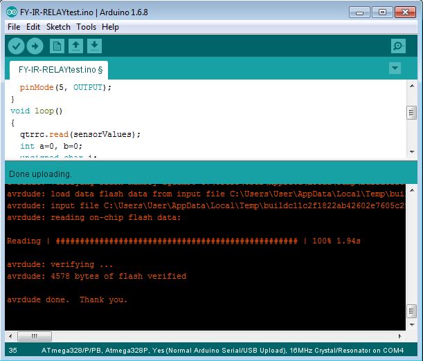
The following shall be seen if the uploading is successful.
To monitor the intensity of the sensor. Rotating disk with black and white strips are laser-cut as shown in the following.
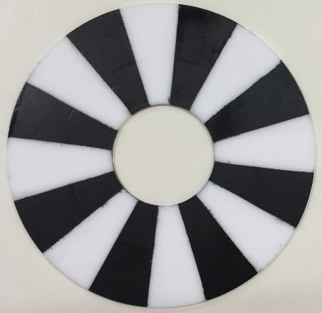
Measurement: Intensity of Reflective Surface (White) & Non-Reflective Surface (Black)
To calls the serial monitor in the Arduino IDE, go to Tools>Serial Monitor. Place and hold the line sensor on any spot within the rotating disk. Try to maintain the distance of the sensor to the disk as the sensor is moved slowly from the spot to the adjacent spot. As the result, the intensity reading will change as shown in the following video.

The intensity reading changes from non-reflective surface (set at 2500 maximum) to reflective surface (reads about 200 when the sensor is about 10mm from the disk). The intensity number 700 in the sketch is the recommended transistion number by the manufacturer. Any reading above 700 is considered non-reflective surface and reading below 700 is considered reflective surface.
The working files can be downloaded here.
Photo Transistor Board and Photo Transistor Schematic
ATmega328 MC Board and ATmega328 MC Schematic