Week 4 - Electronics Production
Tasks:
To build a FabISP for AVR microcontroller which includes milling the circuitry onto the blank PCB board, stuffing and soldering the milled board, and programming the firmware into the finished FabISP board.
What is FabISP?
ISP stands for In-System Programming or some may also call it In-Circuit Serial Programming (ICSP). Click here and here for readings about ISP. Personally, I think it is very similar to PLC (Programmable Logic Controller).
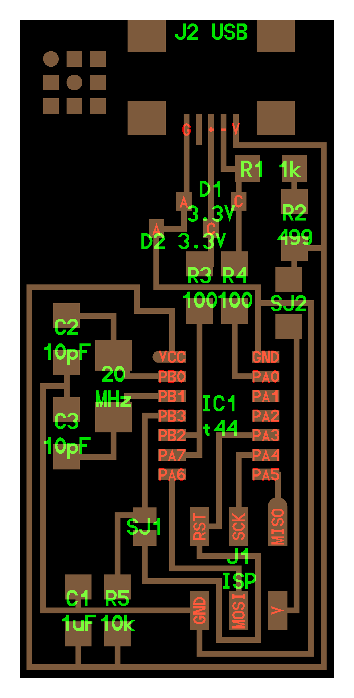
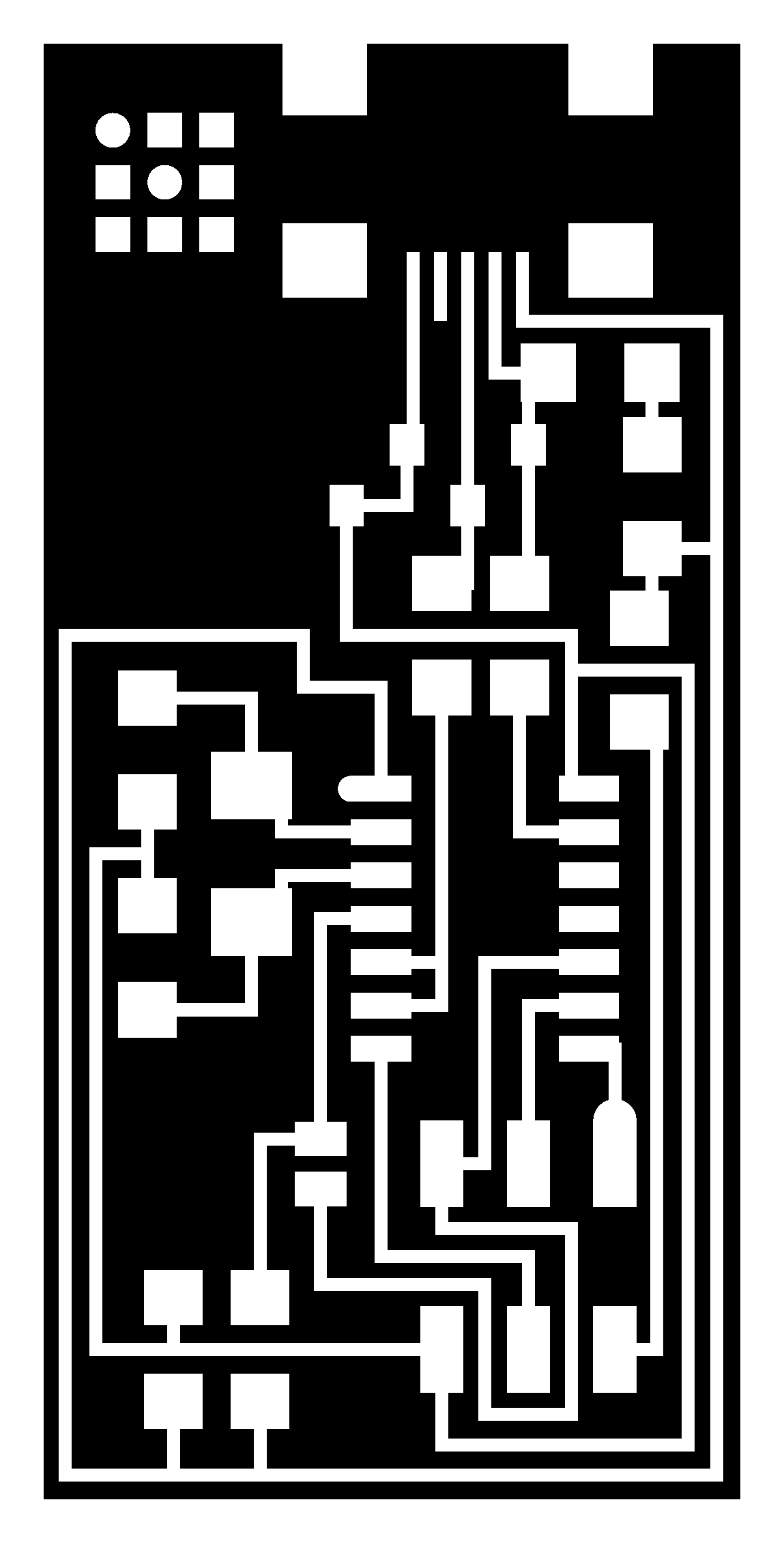
This site uses FabISP Neil which is designed for production within a FabLab. Click here for the circuitry diagram and here for what a finished FabISP should look like. Whereas, the trace (png) and boundary files for milling can be downloaded from here and here respectively. See the following images.
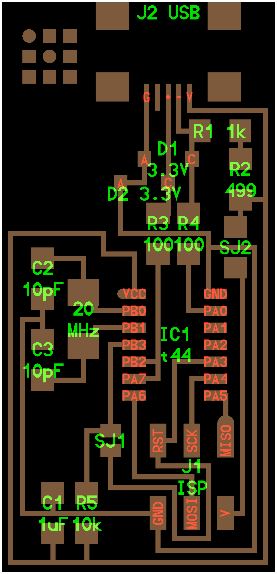
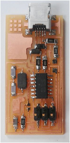
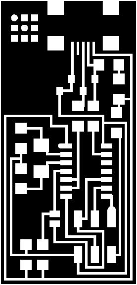

Hello ISP with ATTiny 44, Hello ISP - Trace, Hello ISP - Interior
Milling The PCB Board
FabLab@SP has LPKF Protomat S103, 2D Router and CNC milling machines. LPKF Protomat S103 is a circuit board plotter for producing PCB prototypes in small batches. The trace for FabISP Neil is milled using this machine. Alternatively, 2D router and CNC milling machine may also be used. The difference is in the files that the machines are able to read, process and execute. LPKF only reads Gerber file which can be generated from Eagle software whereas others may read g-codes which now can be easily generated from fabmodule.org (thanks to Neil and teams for writing and sharing the handy fabmodule).
The following webpages and video links are used as references/guides to milling the FabISP board.
- www.build-electronic-circuits.com/gerber-file/
- academy.cba.mit.edu/classes/electronics_production/traces.mp4
- academy.cba.mit.edu/classes/electronics_production/interior.mp4
From .png to Gerber File through Eagle
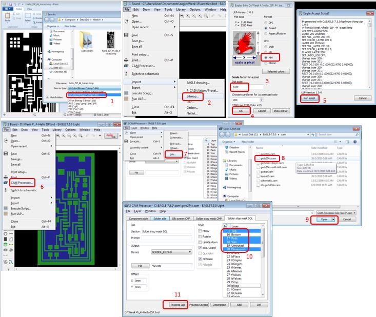
1. Original images is in .png and Eagle only recognizes .bmp file. Thus, the conversion from .png to .bmp is done through Paint application . ie. Open the "hello.ISP.44.traces.png" using Paint >> Do a file>Save As>Change the save as type to .bmp as shown below. [STEP 1]
2. Launch Eagle. Go to New>Board >> File>Import>Bitmap...>'select the bitmap file >> Scan used color> OK >> Under Unit, select MM, under scale factor, put key in 0.02. Then OK >> Run script. [STEP 2-5]
3. Save the file as .brd. Next, go to File>CAM Processor... >> File>Open>Job...>'gerb274x.cam'>Open. Under "Layers", highlight 'Top, Pads, Vias and Dimensions' > Process Job. 2 files used in Protomat S103 will be generated, ie. .plc and .cmp. [STEP 6-11]
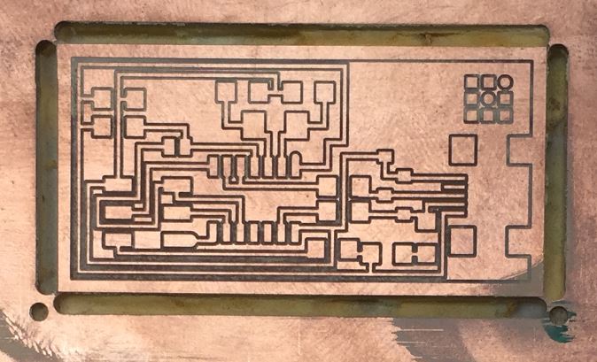
FabISP board milled with Protomat S103.
Once the board is finished, the next important step is to check for connectivity using multimeter.
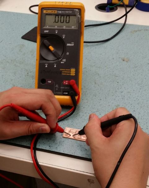
Connectivity checking the milled FabISP with multimeter.
Stuffing & Soldering The PCB Board
Since the components provided are SMD (Surface-Mount Devide) type, the components are all placed directly onto the surface of the PCB and soldered.
Note: Clean the milled board with soap water before stuffing to remove any contaminations and dry it thereafter. Since the components are relatively small, solder iron with fine tip and fine solder wire (<0.5mm dia.) is preferred. A little flux helps in making the soldering clean and nice.
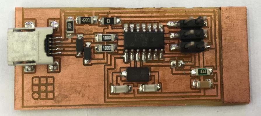
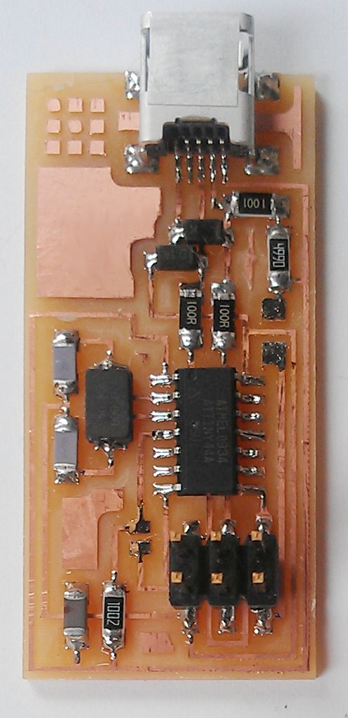
Finished soldered FabISP board (2nd attempt). First attempt failed due to too many short circuits.
Programming The Firmware into New FabISP
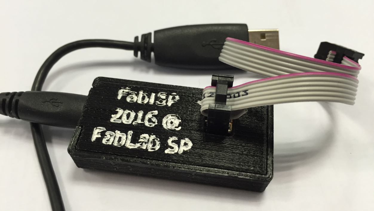
This documentation is closely followed to program the new FabISP board.This FabISP board is programmed by another FabISP programmer board. The following shows the set-up.

Within the Ubuntu's Terminal, the following steps takes place.
    sudo apt-get install flex byacc bison gcc libusb-dev avrdude (to intall Avrdude)
    sudo apt-get install gcc-avr [type 'y' when prompted](to install GCC)
    sudo apt-get install avr-libc (to intall Avrdude library)
    sudo apt-get install libc6-dev (to intall Avrdude library)
    Download & unzip the Firmware from this link
    nano Makefile (to edit the Makefile)
    Remove the '#' on the line within the usbtiny and add the '#' on the line within avrisp2. File save after that.
    The following steps are needed to compile the firmware
    make clean
    make hex
    make fuse
    Last step is to program the board to be an ISP
    make program
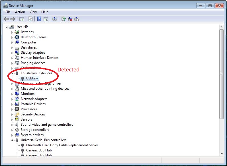
One last step after finished the programming is to remove the jumper wire/bridge and the 0 ohm resistor. Thereafter, plug the FabISP to your working computer to check if the FabISP is detected.
For windows 8 operating system, the following screen shall be seen.
If error messages: "The driver is not updated/found", you may like to download, unzip and install the driver from the following link.
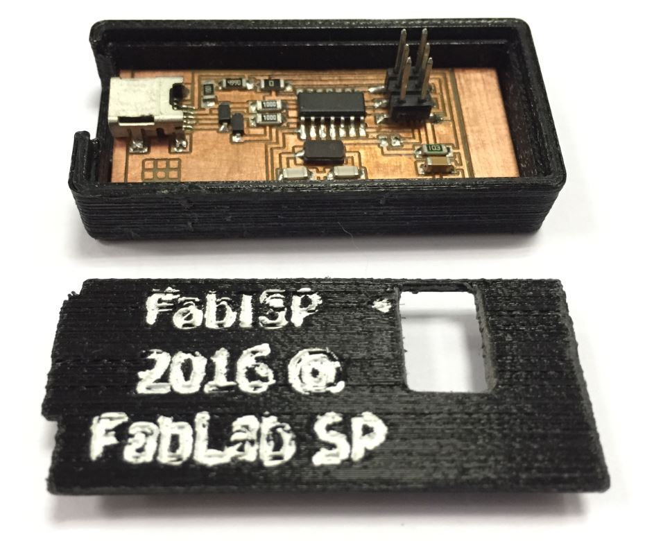
3D-Printed FabISP Casing
3D-printed FabISP casing (FabISP Neil) for sharing if interested.