09& 10. Mechanical Design, Machine Design
http://archive.fabacademy.org/archives/2016/fablabsingapore/mtm/mtm_grp2/index.html
What are we buliding?
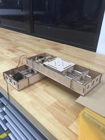
After discussion, We have decided to make a xy-axis machine that drives a pen to draw various shapes on a piece of paper.
As I am not a good artist, so I cant draw well, in fact i always fail my art during school time, so that i hope this machine can help me to do a nice drawing.
A XY machine can move x and y axis. It can be put into a lot of application such as drawing, shooting game etc. We decided not to do z axis as it is much difficult for us.
Workload Distribution
As this is a group project spread over 2 weeks (30 Mar - 13 Apr 2016), we have decided to split up the workload as such:
Designing of the housing using AutoCAD - Tham
CNC Routing of plywood stoppers using StarCAM 2D router - Tham
Lasercutting the design using Epilog Fusion M2 40 - Kaichi
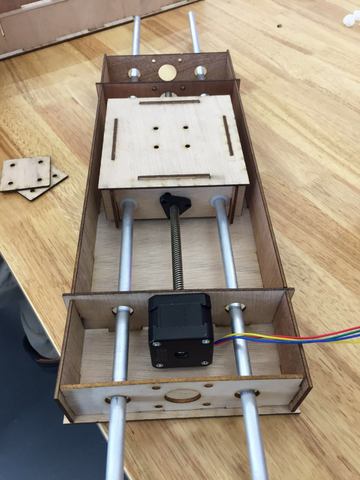
Assembly of the stepper motor housing - Kaichi & Tham
Programming on Mac platform - Mark
Programming on Windows platform - Siew Chin
Modifying GUI codes of wxGestalt IDE - Mark
Designing and making a "gun" which can load rubberbands - Mark
Milling of FTDI board - Siew Chin
Soldering of FTDI board - Kaichi & Mark
Video-editing - Siew Chin
Documentation and update of group page - Siew Chin
For design, plan , etc. is inside Our group page so I will not repeat it here
What did i contribute? and slove technical problem.
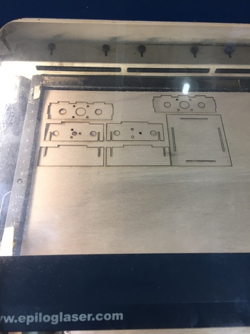
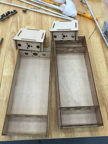
I use laser cut to cut out the design and assemble it. We would be using 2.5mm thick plywood as that is the material we have been given. As we use AutoCAD to draw and export as PDF and import to corel draw to laser cut, seems the PDF having problem all the dimensions are not right. In the end we export as .dxf and it working fine. Firstly I get the design from Tham and we export to corel to test out together, we did few cut to try out the size, fitting etc. Then we notice that all the hole and slot are in different size but our drawing is correct. i dont know is it the limitation for free ware, or the way we export have problem. I learned my lesson so next time I will save a file in different format and check all the size.
|
|
I also help my teammate to mill the PCB board and do some troubleshooting. The board we mill always have problem. We burn 4 motor driver because we put the motor driver to the motor and power on it so that the motor driver become a short circuit. After physical check, there are no burn mark on the board and seems like all component are working except the IC. So we decided to take out the IC and flash it.
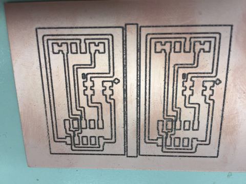
The following 3 pictures are the motor driver that we spoil.First I remove the IC from the board.
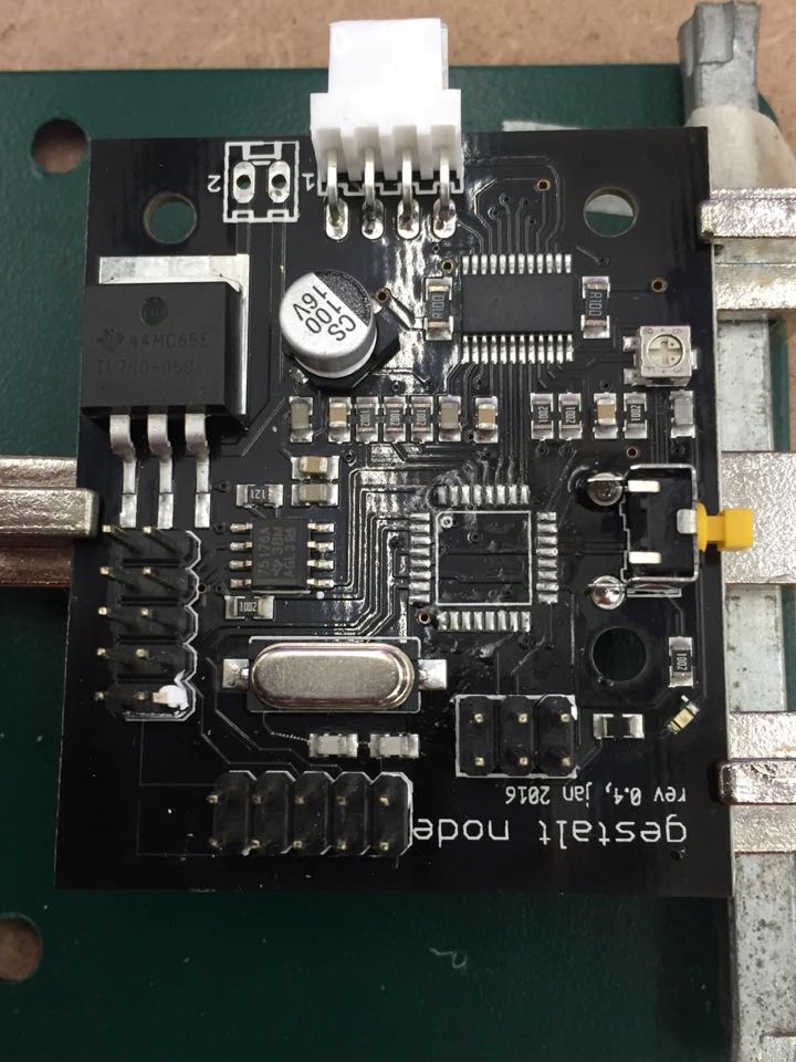
I solder the IC back to the motor driver.
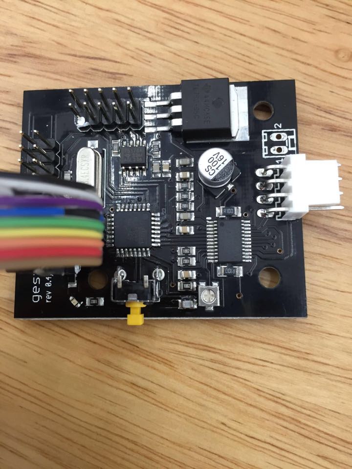
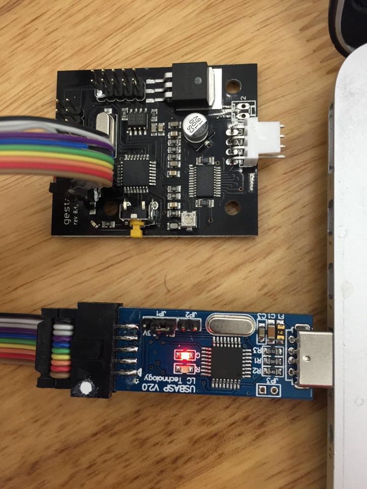
Flash the motor driver.
Opportunities for improvements in the design
I think our design can put z axis. The z axis allow the end effector to move up and down.
By doing that, we need to re design the machine structure and add it one more set of motor. We need to have another brainstorming session.
I think we can improve on the GUI also when someone click the mouse, then z axis will move down and start drawing. When the mouse is release, z axis will move up. With this function, we can not only draw continuous line, we can do a lot more with this machine.
Since our machine have 2 function now, we can change the end effector to other things such as milling machine, 3D printer etc. We need to design in such a way that interchangeable friendly.
For More information, Please go to Our group page.