Week13
Introduction to this week
1. Output device
This week I Choose a servo motor as my out put device, servo is a device used to provide control of a desired operation through the use of feedback. A servo motor looks like: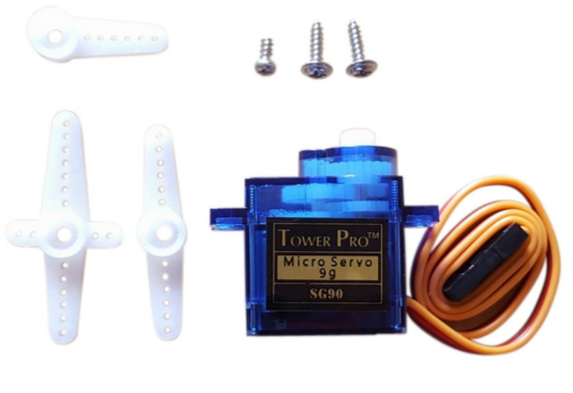 The model of this one is sg90, can be very easily found in Taobao.com
The key to control this motor is to generate a square wave that fits the control logic.

- 0.5ms-------------0 degree;
- 1.0ms------------45 degree;
- 1.5ms------------90 degree;
- 2.0ms-----------135 degree;
- 2.5ms-----------180 degree;
Circuit board design
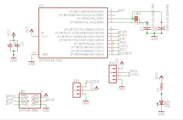
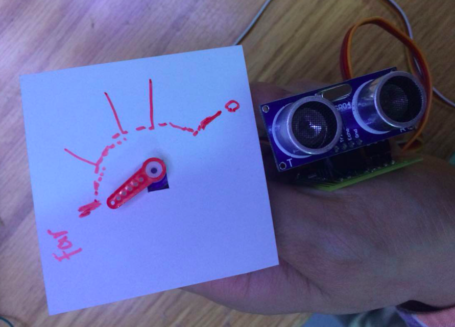
Basically, I only need a output port connect to the signal port of the motor. But considering about the input signal to control the output device, I added another sensor, which will be regarded as input command to the system.As you can see from the layout, I put several holes with pad on the right side. The reason of that is the Sensor is led as contact pins. I put these holes to install female pins.
Tip: Some lines of the circuit board, you cannot link them together. In this case, we can draw 2 pads and it will be easily connectted by sodering with an wire.
The source file from eagle.
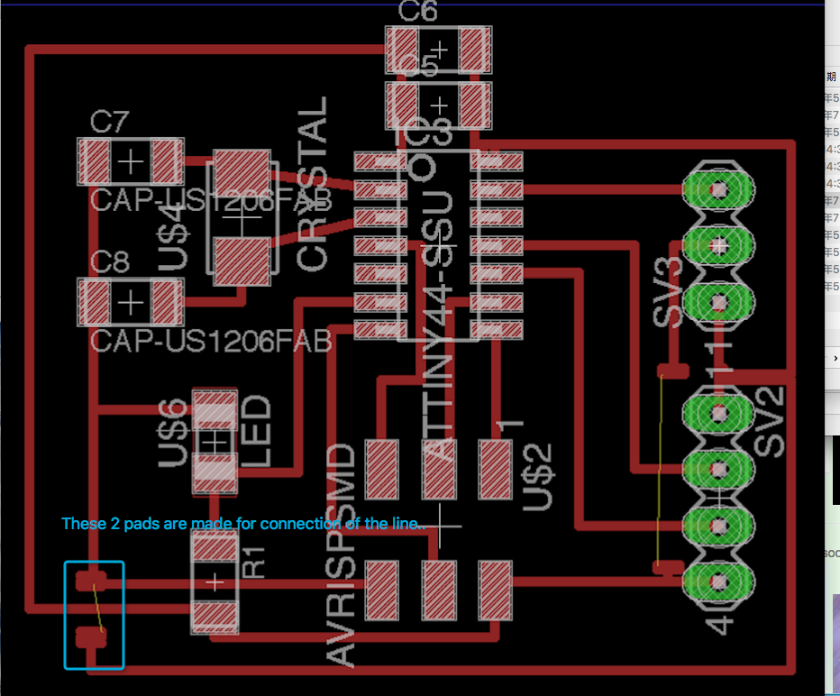
And after the processes of electric production (milling, sodering, assembling...), the circuit board has been made.
Software
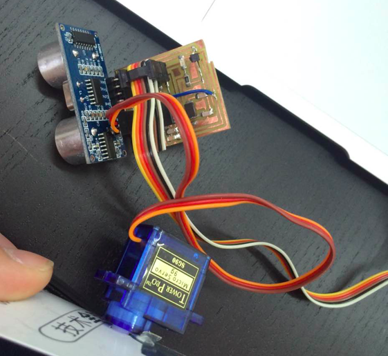
Refering to the hardware we have, I designed the software to make is a complete system. The output angle of the servo will be changed according to the distance sensed by the ultrasonic sensor.The source file of the code.

From the gif we can see that, when my hand close to the the sensor, the handle of servo motor will be rotated clockwisely. And the other way it will e rotaed anti-clockwisely.