What is this about
Color box is a a kind of toys for most of people. It can change the color in many situation which can make people feel relax.
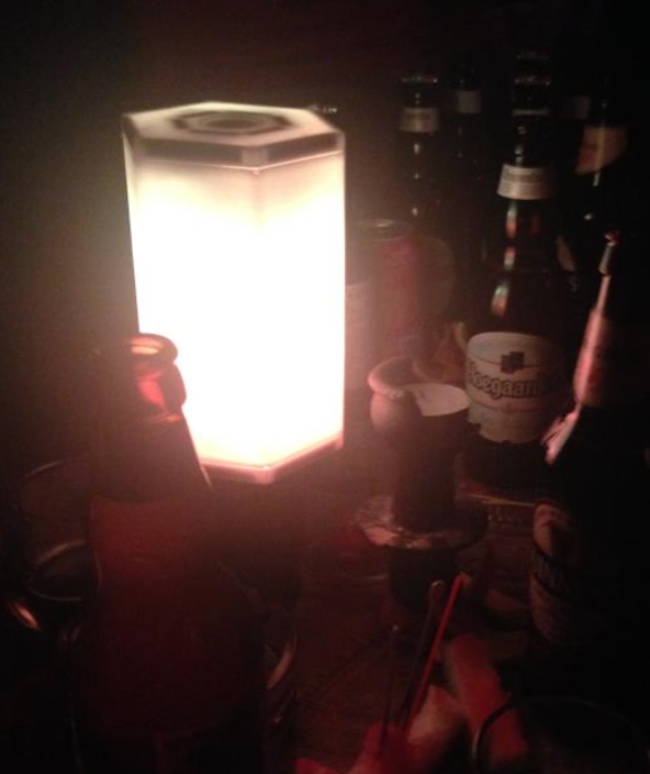
The main function of my design is that when two boxes combain with each other, they can change to a middle color of two box. And when you shake the box, it can change to the origin color.
How to exchange the color
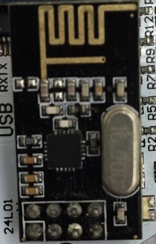
The use of 2.4G wireless module nrf24l01, we can transfer data without physical contact between the two lighting modules via a wireless data transmission technology. As a result of the need for data transmission color fusion to know each other's color values between two lighting modules, each module needs to contain a light nrf24l01. By a magnet and Hall switch layout, the upper and lower surfaces of the two lighting modules connected to each other when the trigger switch Hall opened, thereby opening nrf24l01. Automatic pairing between nrf24l01, and then change the transceiver to achieve two ends of the light module all know each other's color value data. And as long as the Hall switch is in the open state, between the light module it would have been in the process of integration in color.
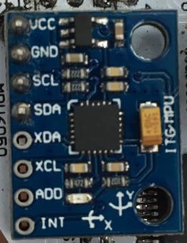
How to shake to change?
By shaking gesture to trigger reset the colors. Reset process is gradual. When detecting the lighting of the state began to shake the color values change to the original color values.
Mpu6050 using an acceleration sensor module, you can Arduino libraries in acquiring the measured current distribution in the x, y, z-axis acceleration and inclination size size. Then the intensity of shaking test and record normal acceleration sensor size of these three axes acceleration features to set the trigger shaking operation range acceleration. Acceleration sensor to determine rocking action.
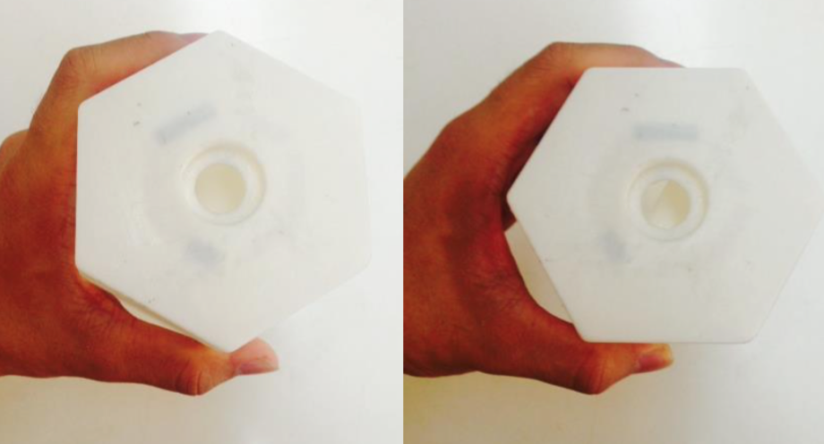
How to place the magnent
This is the magnent i used in my project.

The most important question is how to place them?
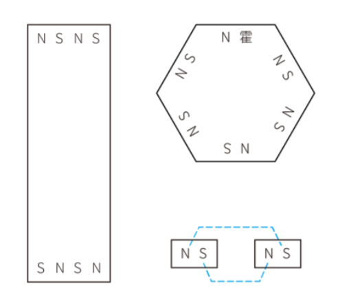
Each light module has eight faces, including six rectangular sides and two regular hexagonal base. Between the same module surface shape can be connected to each other by the magnetic force to be adsorbed onto the iron material.
There are magnets N, S pole distinction between specific distributed manner required to make it possible to accurately adsorption between the light module. In addition, the hexagonal close to the surface when the light module to trigger fusion of color effects, and being close to the judging method is to make the hexagonal faces of the Hall element sensor built surface to the other side of the regular hexagon magnet generating a light module low. Since magnets are snapping the inner wall of the housing, so after the lights go up and the formation of a shadow, visual effects. In view of the shadow of the problem can not be avoided, we can only try to better see the shadow formation.
Using the following layout scheme magnet and Hall switch, all surfaces at any angle you can with other modules to each other corresponding surface adsorption. And in all attached conditions can trigger the Hall switch. In addition, the use of a larger number of magnets, suction is strong enough.
To test the relationship between the size and the distance of the suction magnet, the magnet is fixed to the different thickness of cardboard,
Respectively layout diagram of a plan and program II. In the experiment, a length of 10mm, width 5mm, thickness of 2.5mm small rectangular NdFeB magnets. In the thickness direction of the magnetization. The suction size is 0.90kg.
Experiments found that the size of the magnet with suction from the magnet and the magnet or ferrous material related. When the distance is zero, that is both direct close when maximum suction. And as the distance increases, the suction weakened. When the distance is 3mm, the magnet is almost no suction. Distance is 2mm, a weak suction, but not enough to prop up the weight of the lamp. The distance at 1mm inside, good suction, the lamp can be firmly adsorbed on the iron material. But the distance is less than 0.5mm, the suction is too strong, will lead not easy to separate lamp, even the shell tear. Therefore, when the layout position of the magnet, the housing should be close contact, and minimize the thickness of the housing is disposed between 0.5mm and 1mm.
The PCB board
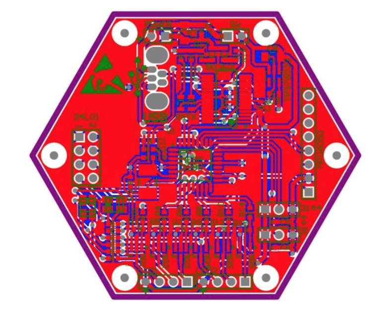
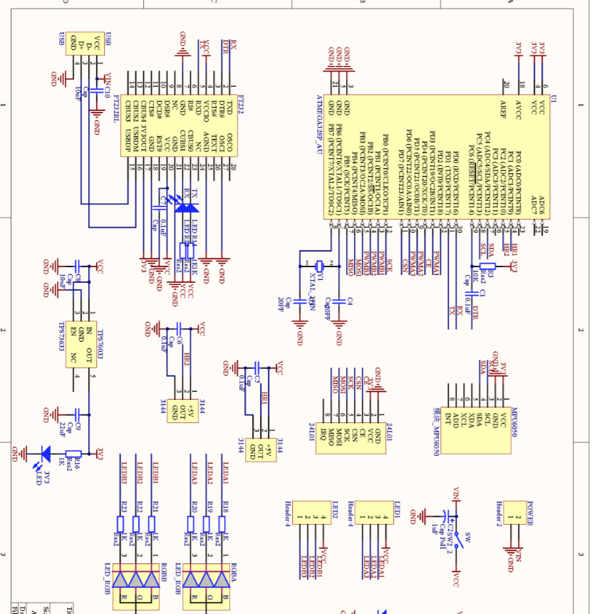
I made the main pcb board which only contains an MCU by milling machine.
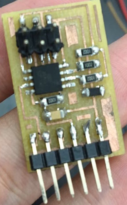
The other part of the board is too complex so i refer to a more professional software - Altium Designer.
Here is my pcb board and some of my sch.
Mold design
i design the mold in rhino.
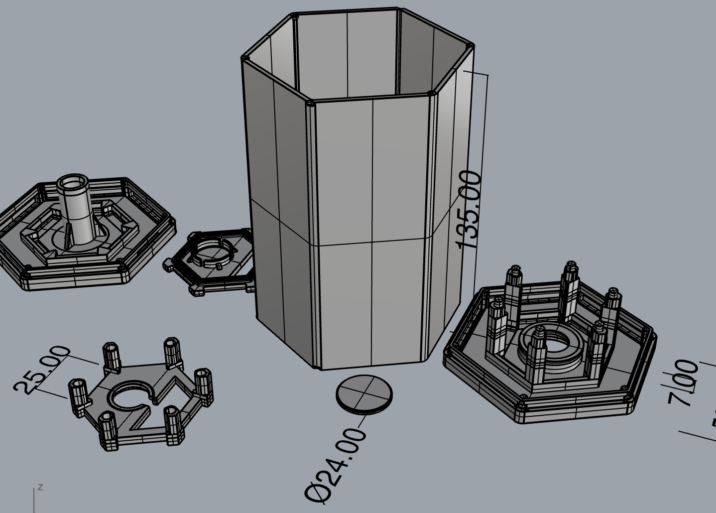
And 3d print it.
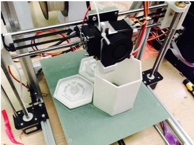
As you can see, i can make all the wire inside the box.
Software Design
i use Arduino to write programs. The whole idea is to program within each cycle of light color only
Change a little bit. This idea of the performance is in the loop cycle, every light color values changed little, and the time required for each step is very short, only a few milliseconds. The benefit of this is to make light color gradients can easily break, the whole system can quickly respond to different inputs.
Every cycle must first determine the status of the Hall element, then so take different steps. When Hall elements have not been activated, change detection and determines whether the acceleration in shaking state, if the state is shaking, then the color values to the initial values of the color change; and when the Hall element is activated, enable wireless color module integration process.
When the connection between the lamp module by regular hexagonal base, light colors gradually blend. Light colors by mixing different proportions of red, green and blue RGB Led in three colors to achieve. Three color brightness range of 0-250. When RGB Led color value of (250,0,0), the light color is pure red. The color values (125,125,0) when compared with orange.
When the color fusion, assuming module A color value of (250,0,0), module B color values (0,250,0), then in the integration process, the module B sends light to the color values B module A , a after receiving the B color values closer to their color values B. Closer approach is relatively R, G, B three values, if their own values corresponding to smaller than the other, the smaller value; if the value corresponding to its own larger than the other, the value increases. Thus, changes in the process module A the average color values as follows: (249,1,0), (248,2,0), ..., (126,124,0), (125,125,0). The average value of the color change corresponds to module B as follows: (1,249,0), (2,248,0), ..., (124,126,0), (125,125,0). Color fusion process is gradual and is interruptible. If in the middle of the fusion of two separate modules, light color module will not continue to change.
How to fusion the color
Color Fusion consists of three parts: a magnet switch trigger Hall, a wireless module connected to each other, light color gradient effect.
To help describe the idea of the program, the following assumptions were three light module A, B and C. The two bottom surface of each light module are X1 and X2, two near the bottom surface of the light bulbs are X-1 and X-2. (X represents A, B and C)
First, when the bottom surface of A and B, A2 and B1, when close to each other, A2 and B1 placed inside the Hall element is activated, then A and B are to be connected into the state.
When the light module is to be connected, the built-in wireless module Nrf24l01 + constantly sending and receiving start signal for the reserved transceiver address. For example, A B will send a start signal, and then switch to start receiving a signal from the C's. In this case, because A and B are to be connected, but C does not. While B also receives the start signal from the A's, since the wireless module to know the message itself is sent by recipient receives, so A and B are soon start signal received by the other party. At this time into a connected state.
After entering the connected state, A sends to B A mean of the two side lamp color values, and sends a completion signal. After receiving the end signal, B according to the position of the Hall element of judgment that bulb B-1 with A closer together. Thus, when the color values B receives from A, B-1 change in four color values, B-2 change a color value. This enables color gradient effect. Then, B switch to the sender, A is switched to the receiving end.
How to made a color box?
This section, I use the simplest form describes how to quickly create a color lights.
1. Prepare the material, according to this bom.
3. The welding control circuit, including a mcu.
4. Welding function circuit comprising a Hall sensor comparison, RF communication module and LED driver circuit.
5. Welding LED light board. This is a rectangular block light board.
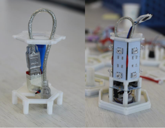
6. I give 3D print file to print all modules.
7. My module is designed well, you can go directly to the circuit board. Intermediate hollow portion to place excess circuit wiring, this will look very beautiful.
8. The programming process.
9. Turn the switch, if all goes well, you'll see one color of light has been lit.
10. Use a magnet close to the bottom of the Hall sensors, if normal, the system will start looking to match the lamp cartridge, this time there will be a slight color change.
11. Make a box again, and the two magnets attached to the inside of the box. Near the bottom, you'll see them in color it!
Some conclude things and makefiles about my project please refer to this page