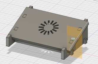
Laptop Stand Design
25 Feb
Week7 Machine Controlled Machining;
---Standing Leg---
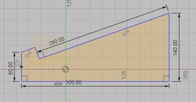
Right click from top menu to create new component - create sketch - select work plane.
Use tools from the sketch palette to add constraint to lines that are perpendicular/ parallel to each other
Add sketch dimensions by clicking on 'Modify' - 'create parameters'. Set thickness to 18mm and 'Legwidth' to 300mm.
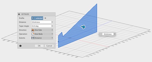
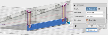
Extrude by 'thickness' as defined.
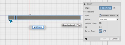
Select all edges from top view by drawing a rectangle. Add 3mm radius. Apply filter function to smoothen the edges.
Activate top layer of the design. Copy and paste component. Apply joint function to position the new stand relative to the first one.
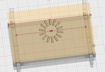
---Surface Design---
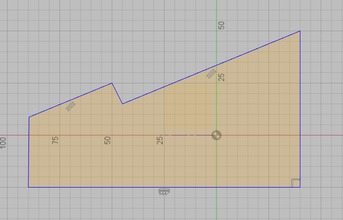
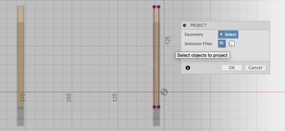
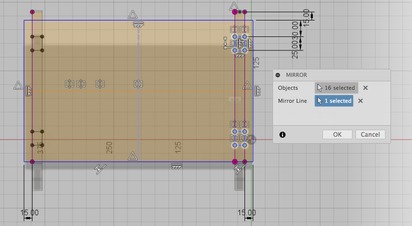
Create new component, the surface of the laptop stand. Select drawing plane, click on Project / include in order to see the lines from other components already drawn as reference. Draw rectangle and constrain it.
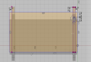
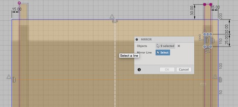
After one tab is drawn, add three others by mirroring. Draw two lines connecting midpoints of the rectangle.
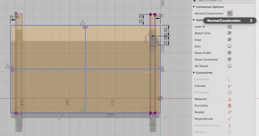
Select the two by holding shift. Turn normal line to construction line. Apply mirror
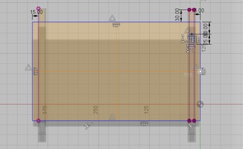
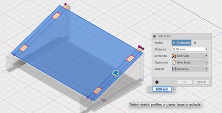
Select all profiles I want. Extrude.
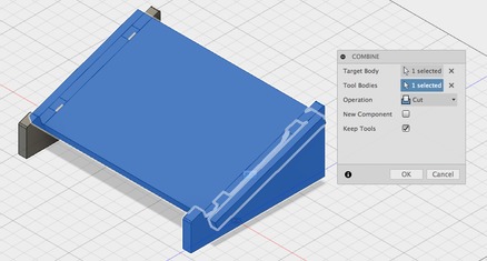
To remove the surface layer from standing legs, apply combine then choose cut.
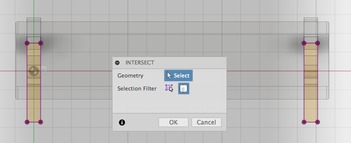
---Supporting Legs---
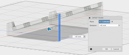
Create offset plane. Select plane. Create new sketch on that face. To see intersects, click project -> intersect. Draw rectangle
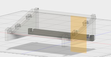
Create a midplane by choosing a front and back plane.
Extrude
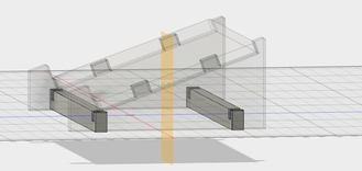
Mirrow
Add ventilating holes.
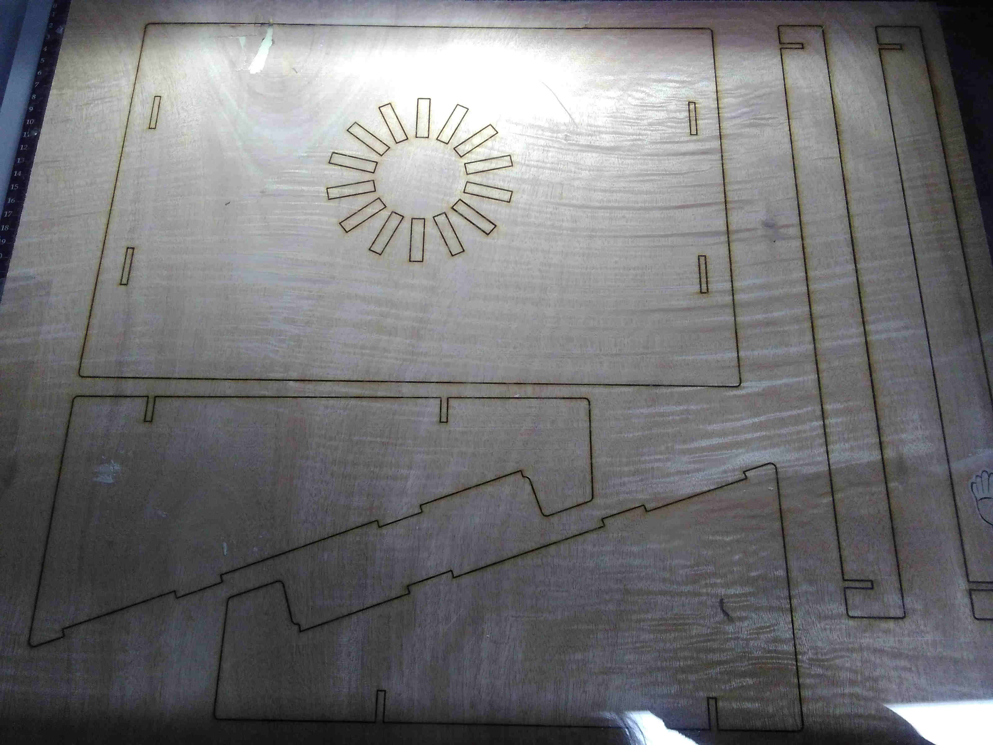
---Export to DXF File---
Create new sketch by choosing one surface of the component then click on 'stop sketch'. Repeat until all components' surfaces are outlined in new sketches. Finally save each sketch just created as DXF file.
☞ TIPS:
1. Triangle showed when mouse hovering above a line means midpoints.
2. Creating an Offset plan is useful when sketching a 2D figure in a 3D circumstances.
Download the design file: Laptop-Stand.f3d