
In this week I have read Atmega Data Sheet and made Satshakit and ISP/FTDI Connector.
Satshakit is Arduino Board but has more capabilities to add up. So, it use more or less same components with Fab Kit.
This is ingredient for Satshakit and to make this one follow the link below.
1 - Atmega 328p (<- P is important. P is the distance between each leg of the ATMEGA)
1 - Crystal 16Mhz/18pF
1 - LED_Green
1 - LED_YELLOW
1 - 6mm Switch
1 - 10K Resistor
2 - 499ohm Res
2 - 22pF Capacitor
1 - 10uF Cap
1 - 1uF Cap
2 - 100nF (=0.1uF Cap)
1 - PAD_1/PAD_2
1 - POWER/PAD_B
I don't know why but I made the older version of Satshakit and this is both versions link.
Difference between old and new Satshakit is 100nF Capacitor is in the board or nor.
This component helps communicate stable with FTDI connector.
Old version of kit doesn't have it I have to attach on the connecting board.
What is Satshkit?
World first live soldering Show.
Recorded Video clip.
This video includes how to solder efficiently, Unsolder, etc.
*Bad Word Warning*
I don't know why but more than 400 people was watching this live show. People are weird these days
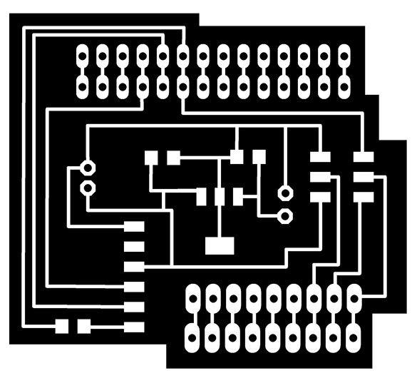
I have down load the Satshakit.brd If you need nice tutorial follow the Link .
Now there are several version of Satshakit. Chose what you want to make.
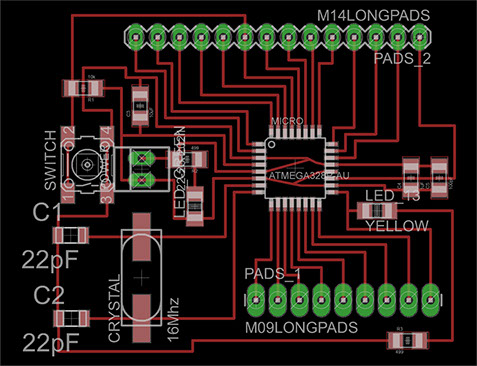
This is one that use for making as you can see there is no 100nF Capacitor and one pin hole. Except those two anything else is same.
To connect with FTDI or ISP you can use filthy wires but let's try to cut connector which has voltage regulator.
Don't do this.
This image is not mine I just googled.
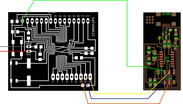
As follow this connection I could make the connecting board easily and learned why I have to put regulator in it.
If you make the Newer version of Satshakit sadly you can't use this connector directly.
modify little and have fun.
connector <-Schematic for my board.
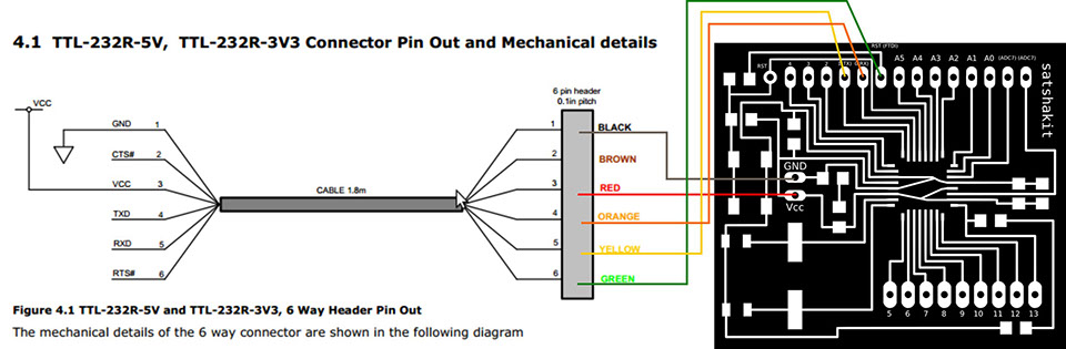
This is the ingredient you need to make connector
1 _ LM2940 Regulator
2 _ 0.47pF Capacitor
1 _ 0.1uF Capacitor
n _ Female Header
3 _ Double male Header
Double the pin holes
for the Future works.
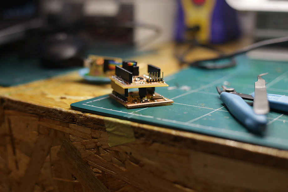
After cutting and solder the components you can use like this and the thing is you can keep use the whole pins while connecting with ISP or FTDI.
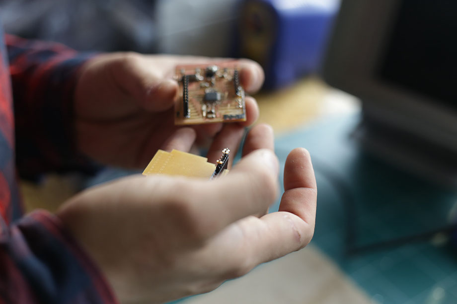
While my lovely instructor gave me a tip how to solder properly he breaks some of my connections. And he fixed it If I was try to fix it must be take more than Thousand years...

It was the moment that My instructor Explain about Bootloader.
I can clearly get what the bootlader is. :)

Bootloader is simply the base of the board which you can upload or debug.
Without boot loader you can't communicate with Operating System it means you can't use the board.
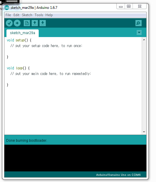
You can burn bootloader with Arduino IDE.
The sequence is very simple.
connect with correct direction with Fab ISP and it will turn Green LED on.
If not you should check the connection of the connecting board and the direction of the LED. A to C remember.
and choose correct things at Tools tab; fab ISP/Arduino UNO
and hit burn bootloader in the Tools tab and TaDA!
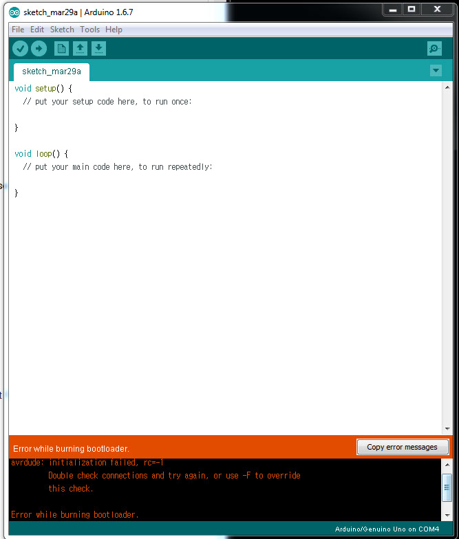
Error................
most of the error caused by bad connction,
I check the board with multimeter and fix the whole connection luckly there was no problem with connecting board.
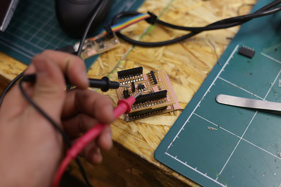
After fix the 7 borken connection with ATMEGA
bootloader has burned.
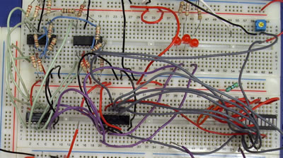
And I tried some Example code on my Satshakit.
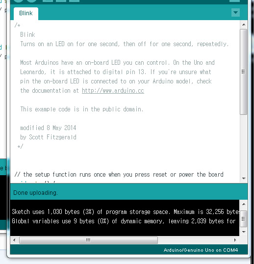
I upload the Blink on my board and It works!
:)
It Works!
Files
Back to home