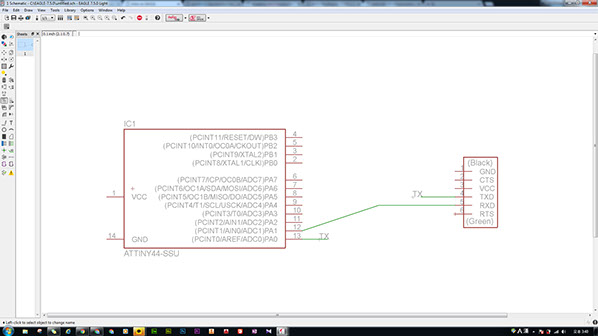
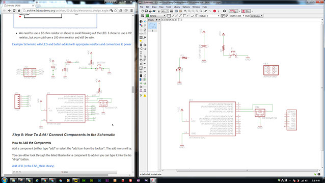

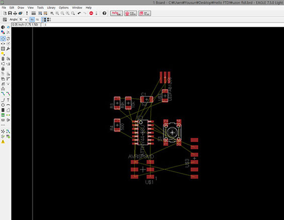
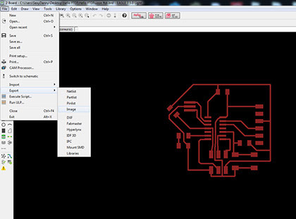
After you make all the components connect in Schematic turn in as a board. And you will see the screen just like the picture above. black and yellow and red-ish orange.
Yellow Line means the connection that you have made in schematic.
Red means your components.
You can make a lot of layers in Board.
In this week I just want to avoid the adventure so just like a lamb I have followed nice tutorial that I have mention already.
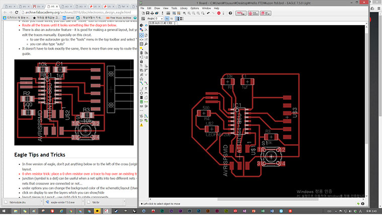
connect every thing and simply change some look by using routes.
After you make all the route. you have to check it whether it is going to be cut well or not.
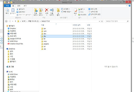
So, down load the fabmodule.dru and put it in the eaglecad's "dru" folder.
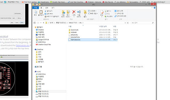
Aright. Copy and Paste
after that simply hit "DRC" which stands for Design Rule Check.
and load fabmodule.dru
after that look at the screen whether there is problem or not.
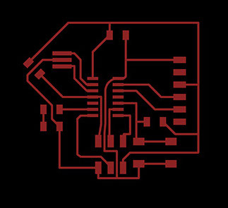
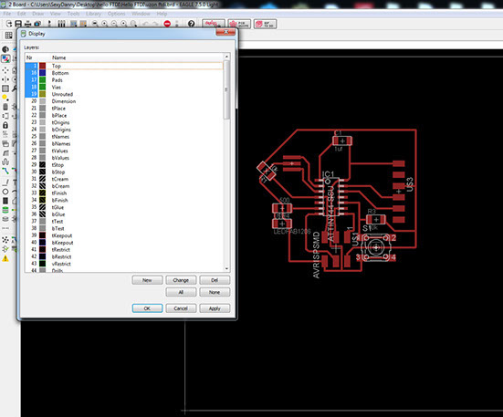
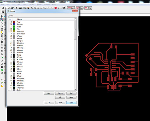
Check the layers and let's hide all the names.
You don't need it for the making trace out of it.
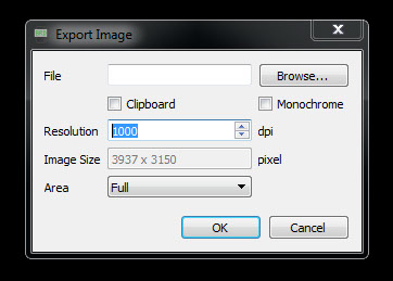
In the eaglecad tutorial they recommend you to export png in 500dpi but you have to do it with more than 1000dpi. If you try with 500dpi you will get awful trace. (I didn't try but one the other fab academy student told me.)
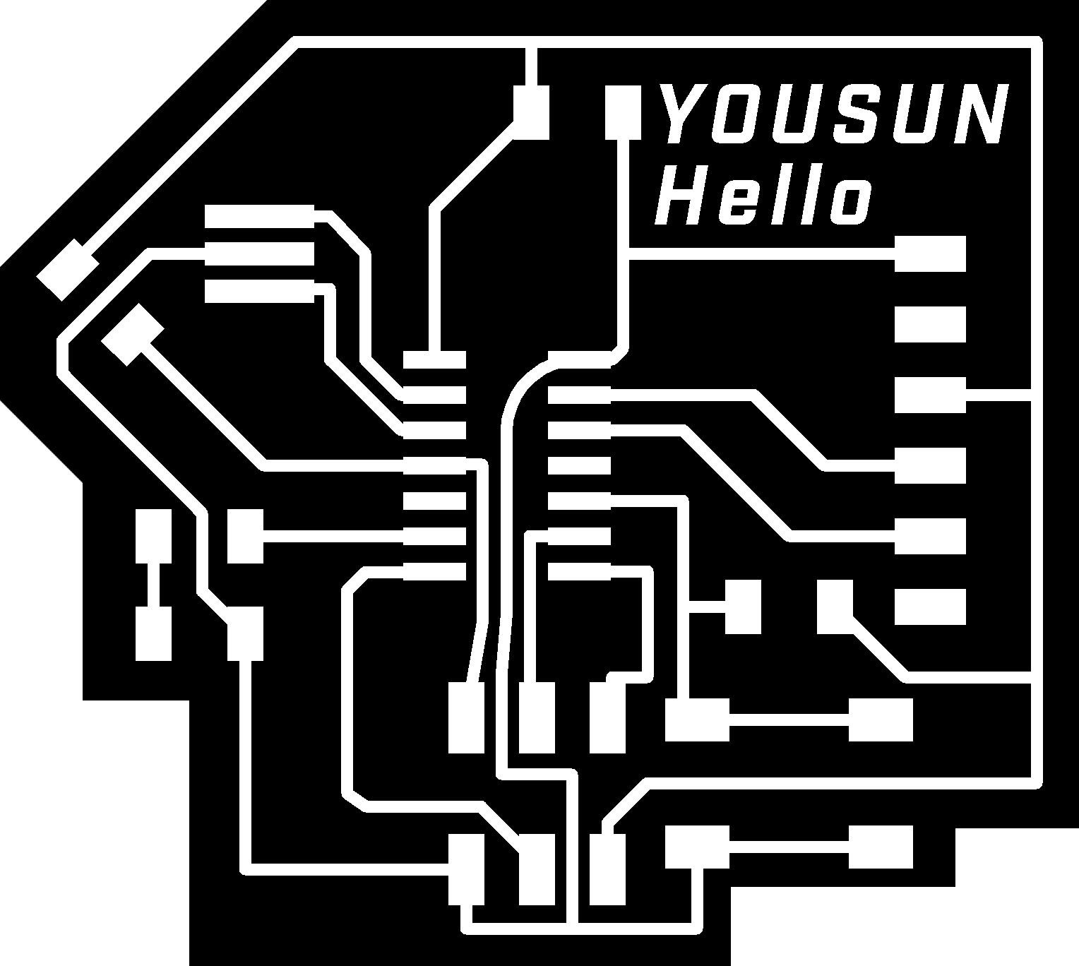
Don't forget to check "Monochrome" to make it b&w image.
If you want, you can cut mine you can modify my board.