
Computer-Controlled Cutting
pressFit CNC axis

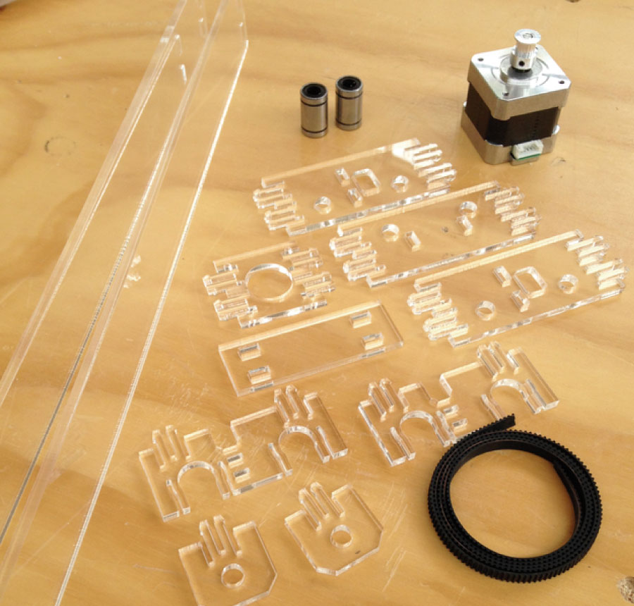
parts used
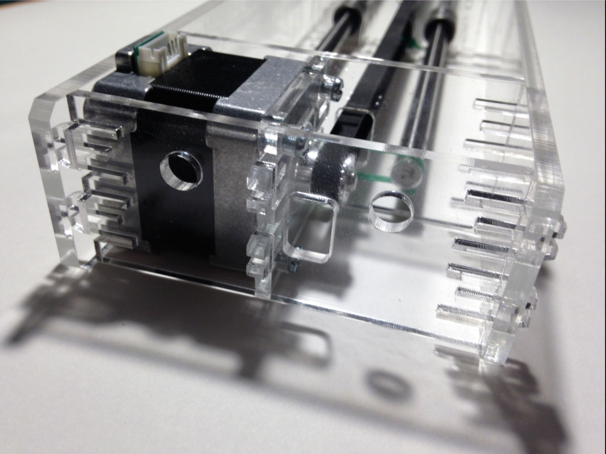
- 1x NEMA 17 stepper motor
- 1x Timing pulley 2M and belt
- 2x 8mm Inox linear shaft 398mm
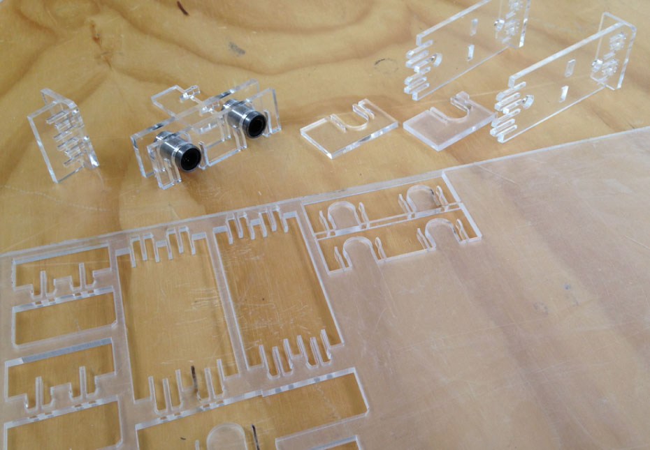
- 2x 8mm Linear bearing
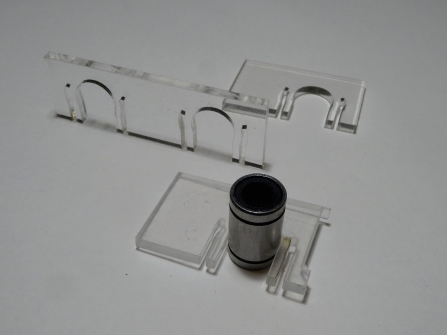
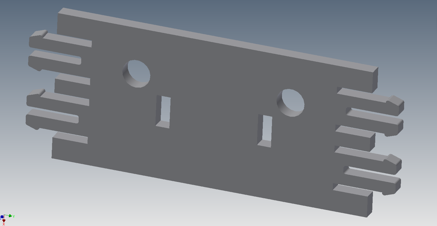
The pressFit for the linear bearing.
Adjusting the principal joint system of all the assembly before starting the design of the axis. The difficulty of a parametric design is the propagation of changes, so I keep it simple, this piece is adjusted by a Thickness and the dimension of the linear shaft.
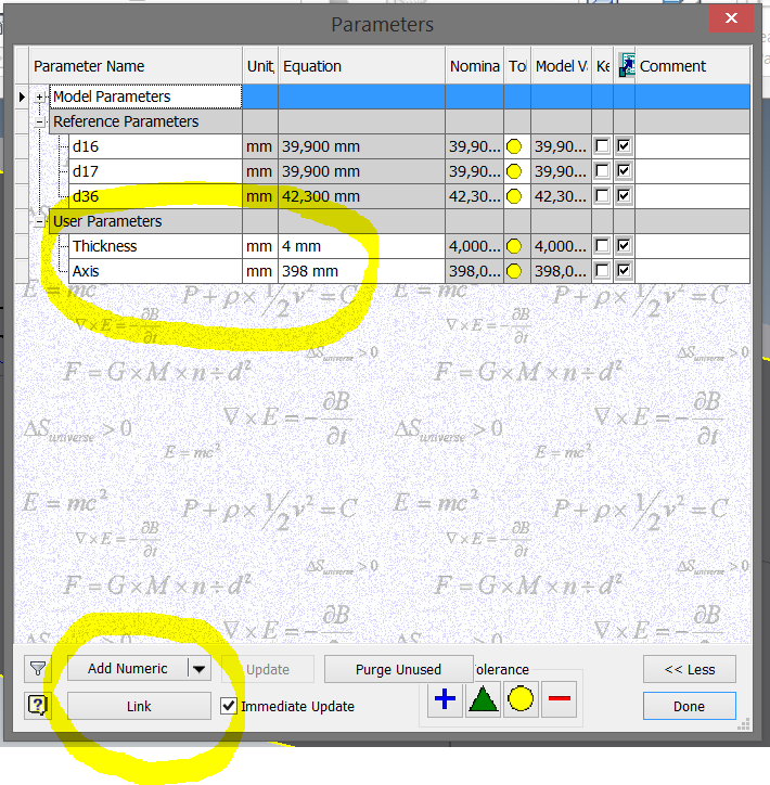
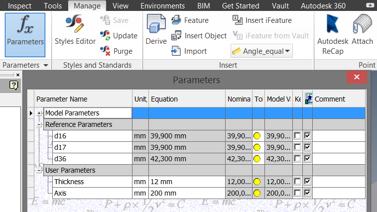
In the parameters options of the "manage" menu in Autodesk inventor 2015, I create two parameters that were propagated to the others parts using the link tool in the parameters menu. In each new part, I link these two parameters from the first part.
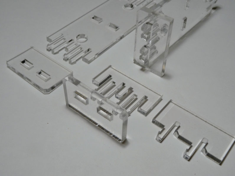
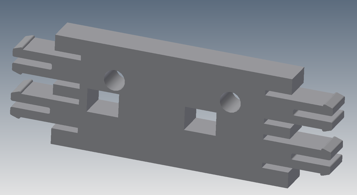
Using a simple geometry as base volume I define the pressFit joint in only one corner, then using mirror to propagate the joint the others corners, so when you change the "key joint" all the corners change.
In this case the thickness is 4mm.
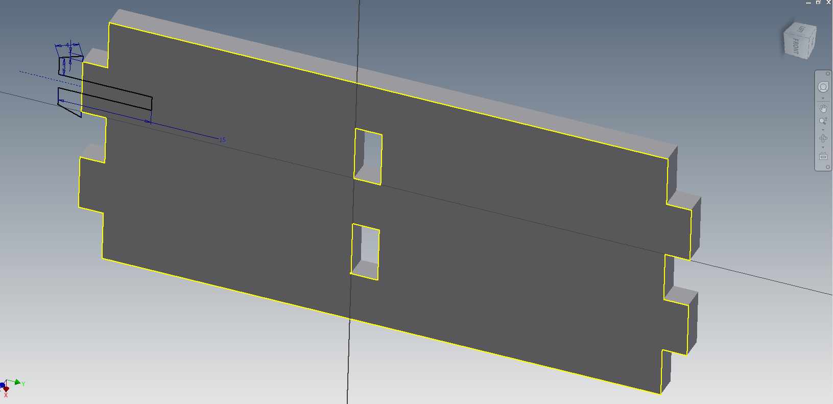
Here I change the thickness parameter to 12mm. This parameter is useful for changing material and also for calibrating the joints by microns if you want to get a perfect fit that makes "clickkk".
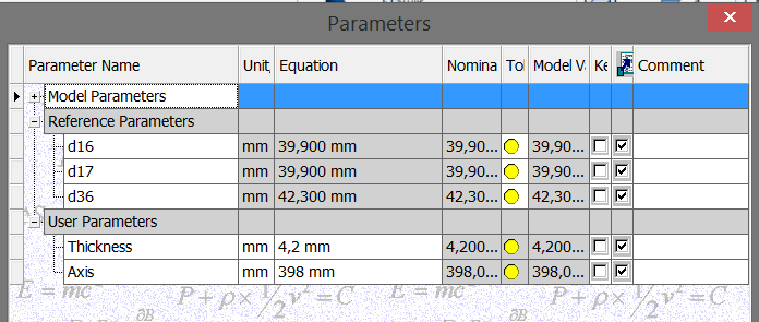
This thickness is 4,2mm, so when I work with 4mm acrylics is easy to assemble the parts.

In this picture, you can see the iteration between 4 to 4,4 mm in steps of 0,1mm. All you need is to change the value and then export the face with the mouse over the face of the part to export, in my case I use DXF2000 so the laser software can import the file.
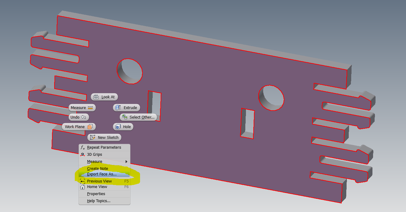
With this step you can export a continuous polyline, I find the best way to directly export a cut pattern. You can also export sketch as DXF.
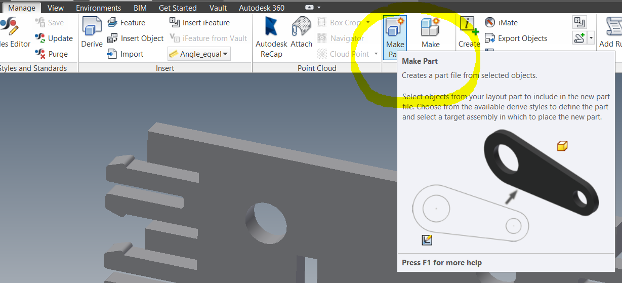
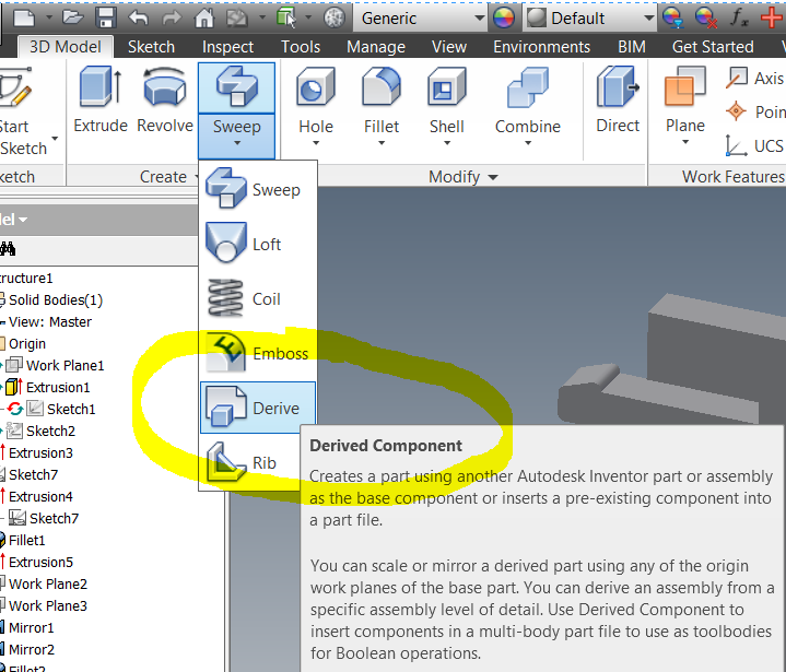
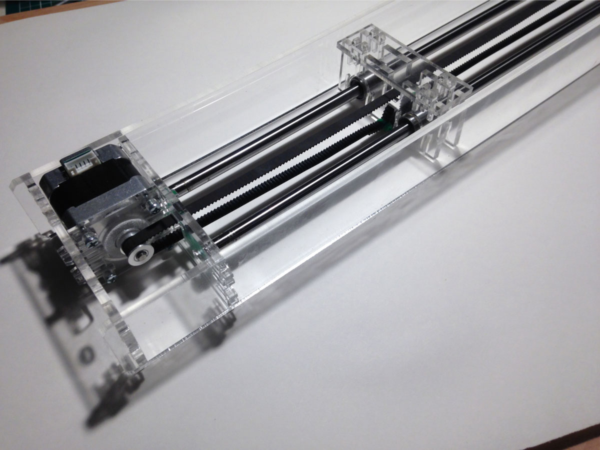
Axis assembly
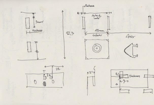
The schematics of the relations in the complete assembly, the most important thing is that the principal pressFit joint is propagated for all the parts in the assembly. So I used the make part options in "manage" and derive in "3D model" contextual menus.
1º Prototype


Changing parameters


You can see that the complete geometry is fine, but it have some issues, by now the assembly is parametric for a range of sizes, it works well in any "axis" size, but no more than 8mm of "thickness"
Laser Cutting

I use Autocad to arrange all the parts and export to .DXF 2000, my LaserCuter uses a software called laserCut 5.3 and read DXF 2000 and illustrator 8 for good results. You can use other formats but in my experience, the format with better results is DXF 2000.
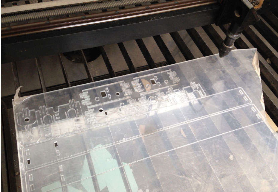


The most difficult part was to get the pressFit working properly, I used the thickness material (in the design parameters, Autodesk Inventor) to give some tolerance to get a good fit, and the way to know if it is working is to hear the sound "click" very clear. Is very useful to propagate the changes in all the design with only one parameter. You can speed up the process.
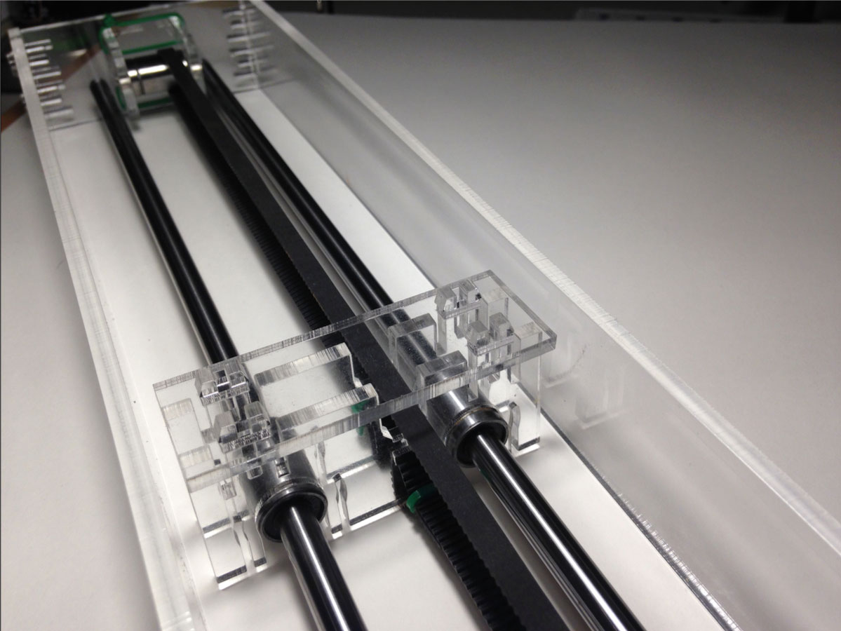
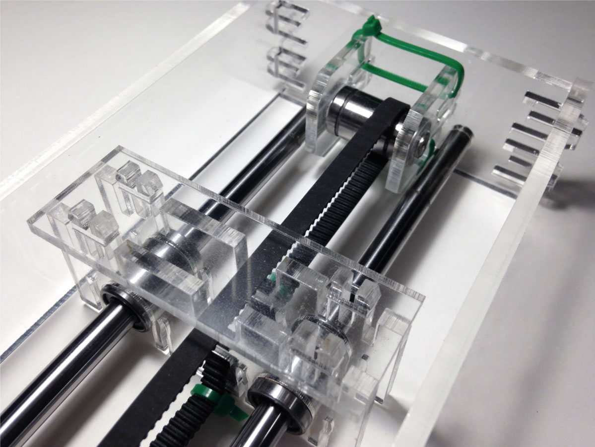
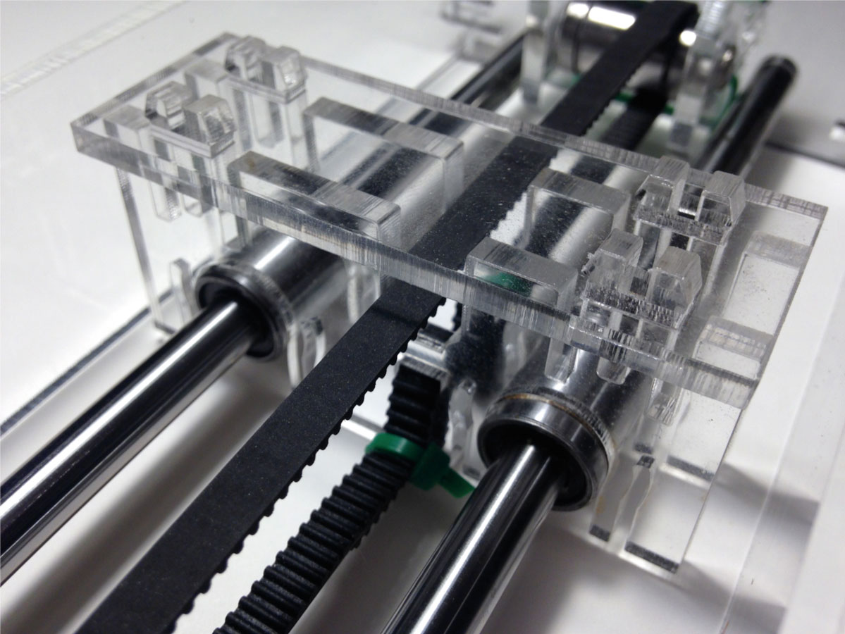
Prototype
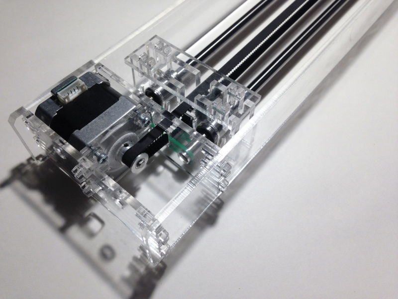
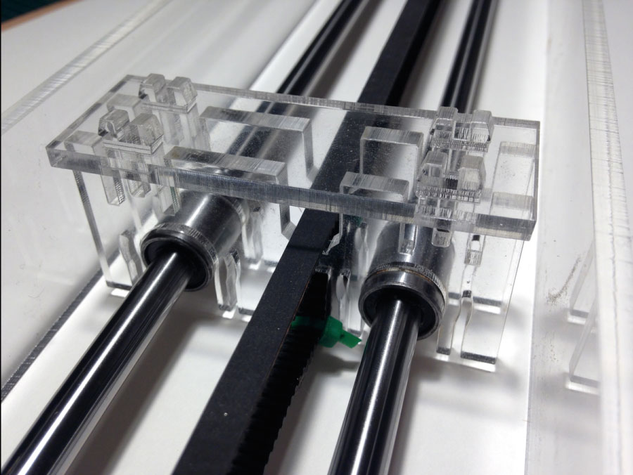
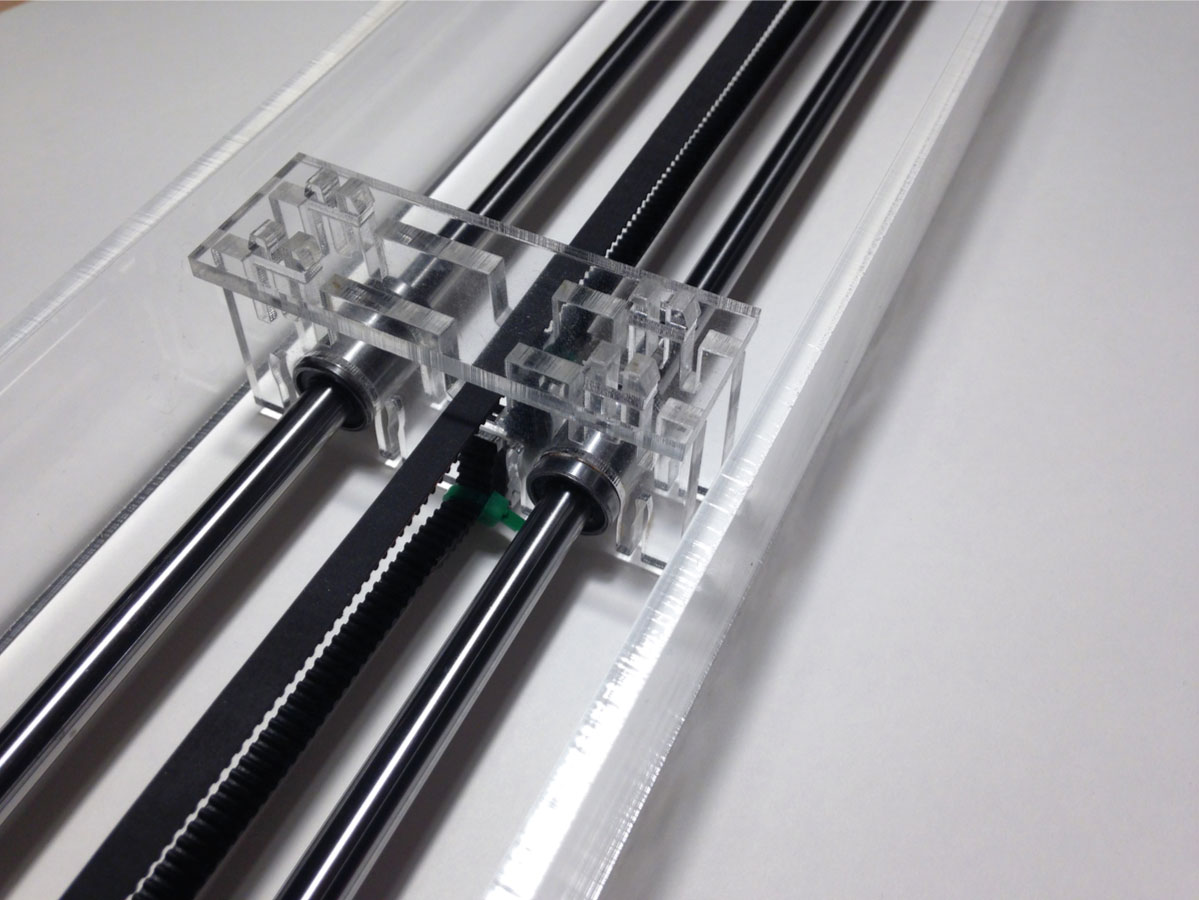


In this pictures you can see that I have to use some wire tie to fix the linear shaft. Maybe for an iteration of the design I could fix the shaft in a better way, doing a pressFit for the shaft also, ass I did for the bearings.

Files
Download parametric design and DXF filesMoving the Axis
For this test, I use a library called AccelStepper modifying the "proportional control" example of this library I can have a relation between the complete turn of the potentiometer and movement of the complete axis. The hardware is a 10K Potenciometer, an Arduino UNO with a protoshield and a TB6560 driver
// ProportionalControl.pde
// -*- mode: C++ -*-
//
// Make a single stepper follow the analog value read from a pot
// The stepper will move at a constant speed to each newly set position
// depending on the value of the pot.
//
// Copyright (C) 2012 Mike McCauley
// $Id: ProportionalControl.pde,v 1.1 2011/01/05 01:51:01 mikem

#include

// Define a stepper and the pins it will use
// 13 EN+ , 11 CLK+ , 12 CW+  AccelStepper stepper(13, 11, 12);
AccelStepper stepper(13, 11, 12);


// This defines the analog input pin for reading the control voltage
// Tested with a 10k linear pot between 5v and GND
#define ANALOG_IN A0

void setup()
{
  stepper.setSpeed(2000);
  stepper.setMaxSpeed(7000);
  stepper.setAcceleration(2000);

}

void loop()
{
  // Read new position
  int analog_in = analogRead(ANALOG_IN);
  stepper.moveTo((analog_in)*4);
  stepper.runSpeedToPosition();
  delayMicroseconds(100);

}
I need to change this line cause the driver I´m using has only Enable, Clock an Counterwise pins
AccelStepper stepper(13, 11, 12);
With this variable (*4) I can define the length of the axis, related to the pot turn.
stepper.moveTo((analog_in)*4);
Work info:
References: Machines that Make, Nadya Peek, Machines that Make: Reconfigurable Stages, highlight.js Autodesk Inventor, HTML5, CSS, Sublime Text, Adobe Illustrator,
Description:
Using basic RepRap components that I already have, the goal of the design is a multipurpose CNC axis, that can be customized in two parameters, the axis length and the thickness of the material. For this purpose, I use Autodesk Inventor cause this software is very precise and can deal with multi parts parametric assembly. .