Molding and Casting
3D model
The design was take from designcoding.net, they share a lot of quality parametric designs.
Toolpath with RhinoCam
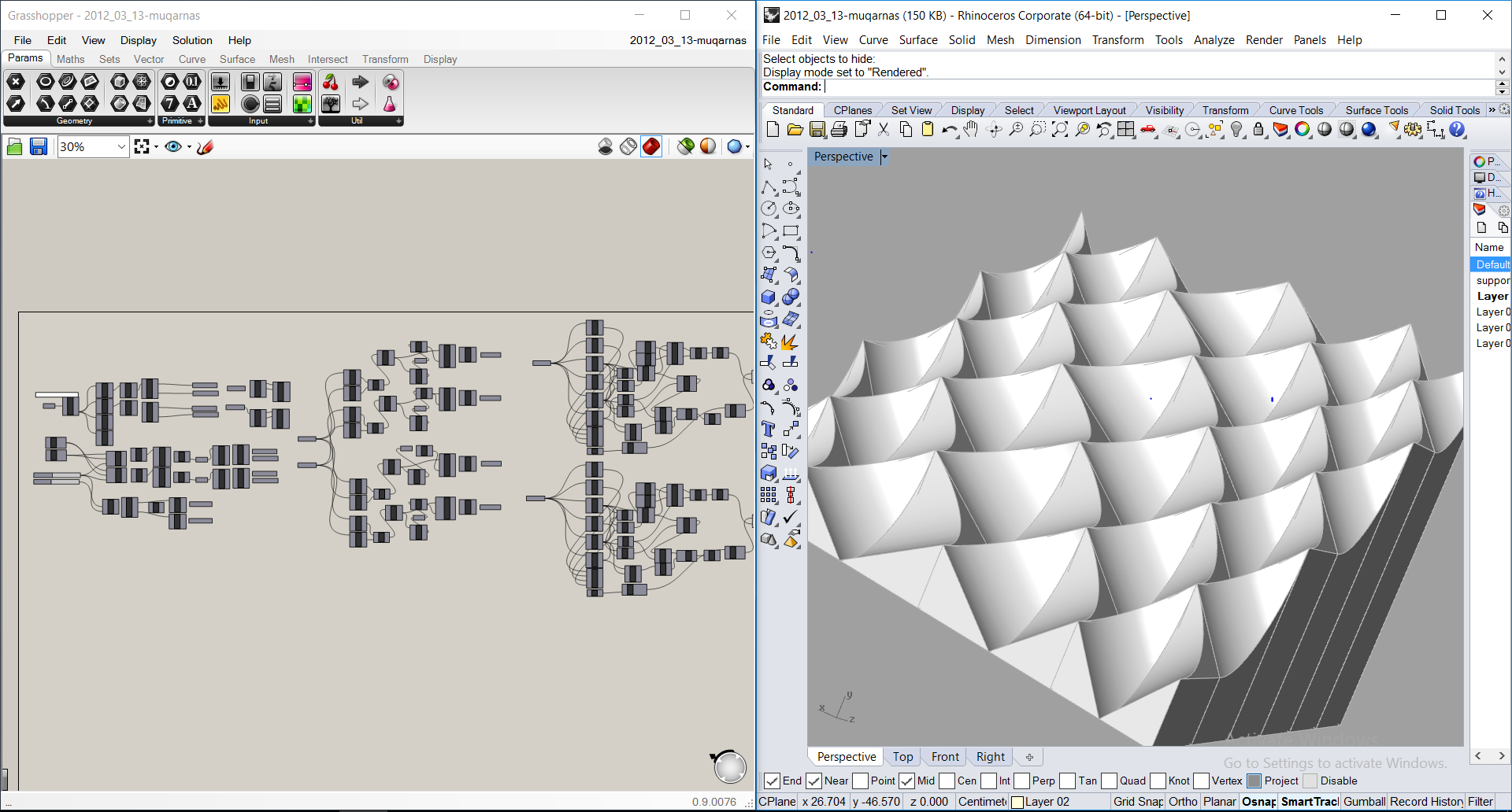
After opening the 3D model and the definition of grasshopper, you have to bake the geometries and then turn it into NURBS object.
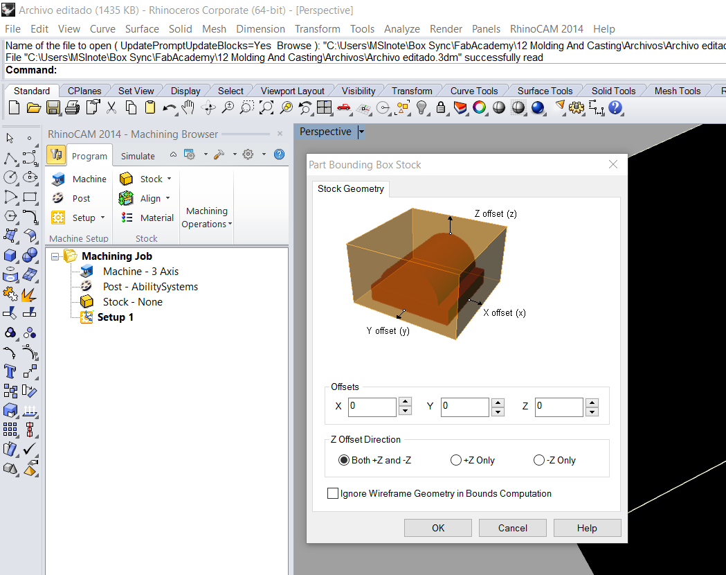
After inserting the object relative to the coordinate axis, must generate a Part bounding box stock. This simulates the actual material.
I always occupied a cutting area to prevent the machining leave the desired area.
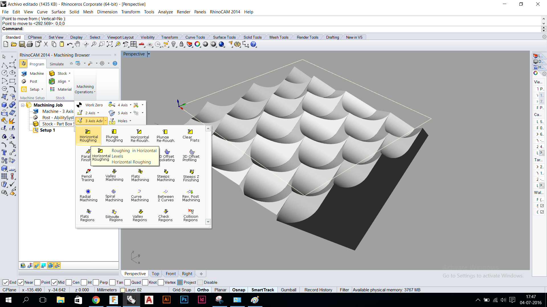
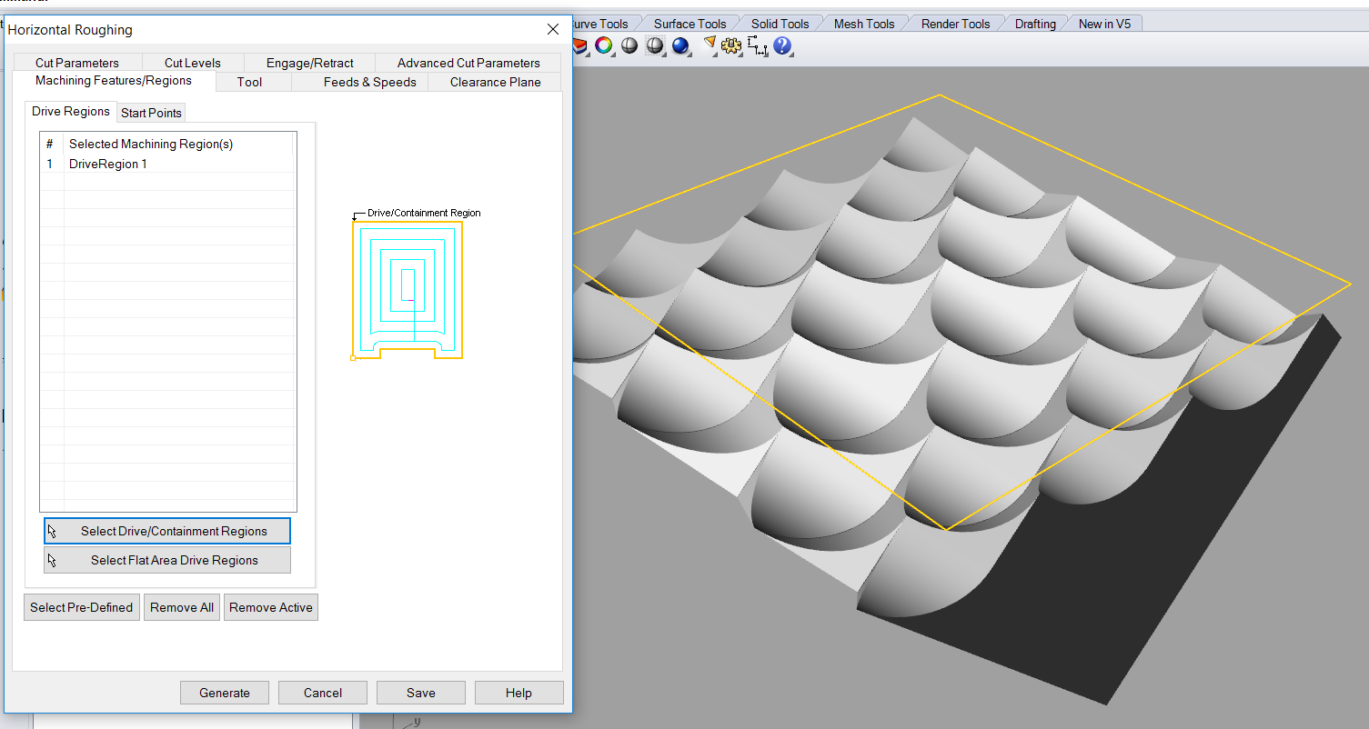
Horizontal roughing to remove excess material.
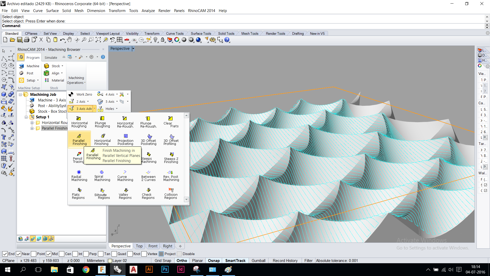
The parallel finishing to start milling the surface with the three axis.
The parallel finishing 90º + 0º
This video shows the toolpath created with horizontal roughing. The operation is been set with 25% overlap, 10mm tool. You can see that all the path is in horizontal layers (z planes), the stepdown is 50% of the tool, so the layers are, -5 z, -10 z, -15 z.
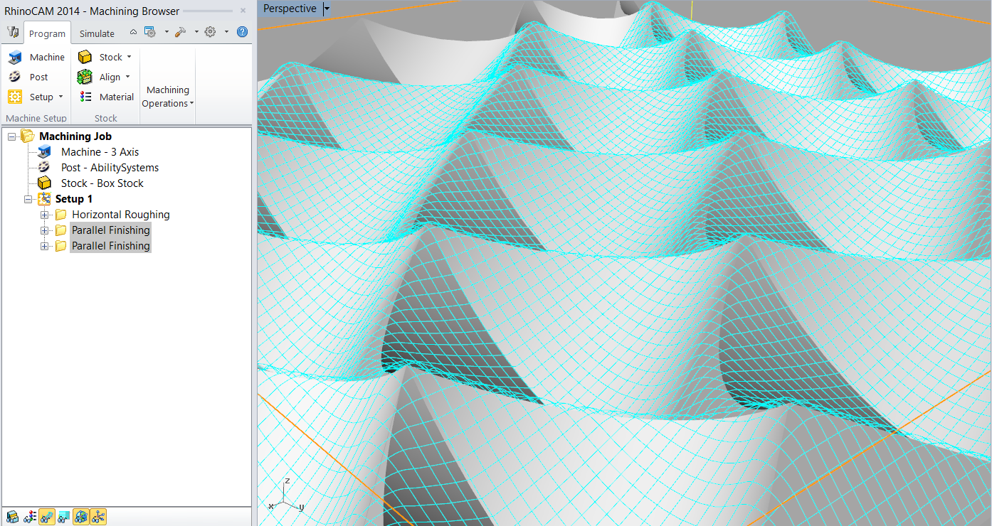
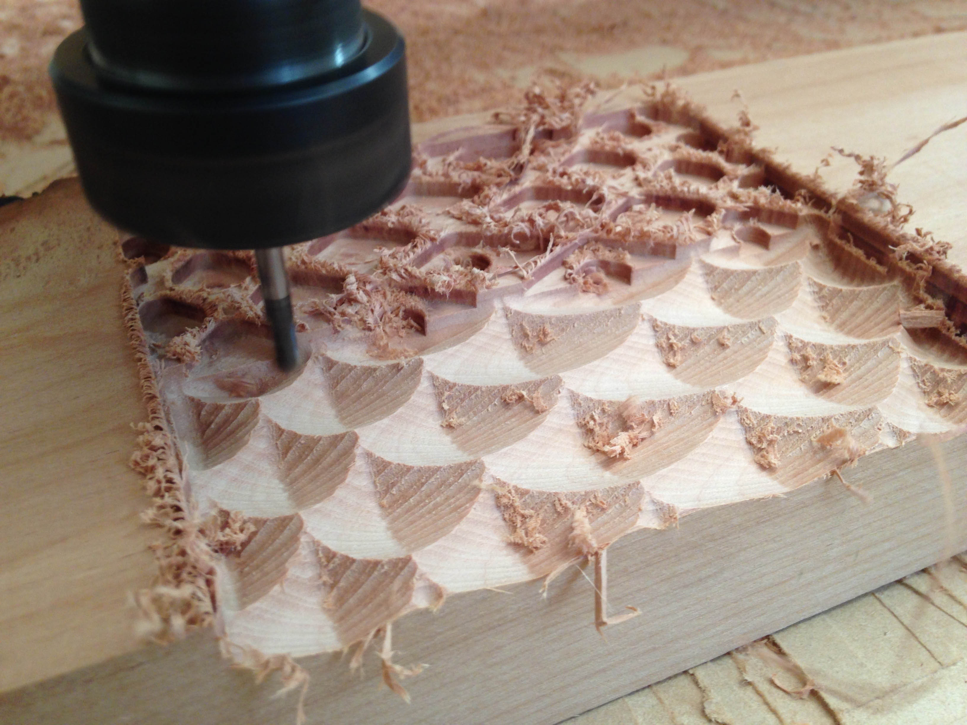
This video shows the toolpath created with parallel finishing 3 axis operation. In this case, the operation is been set with 25% overlap, 6mm round tool, so you can see the scale. The distance between each pass is 1.5mm.
Finally, the simulation shows the toolpath in action, first the horizontal roughing, the first parallel finishing with 0º (parallel to X axis) then a 90º parallel finishing with the same 25% overlap.
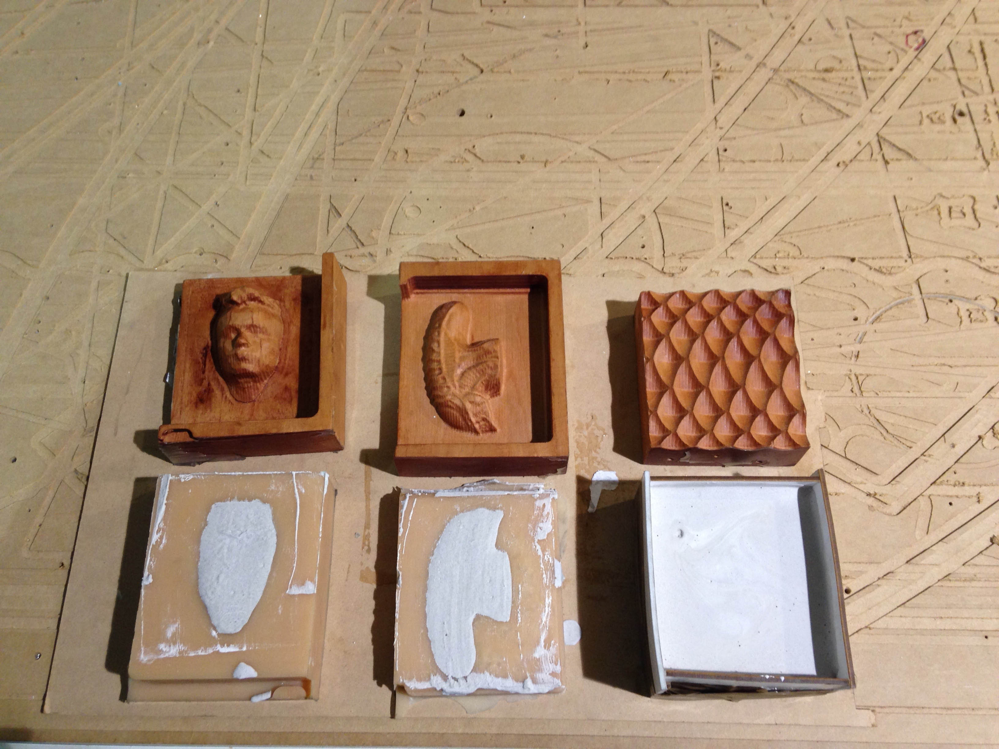
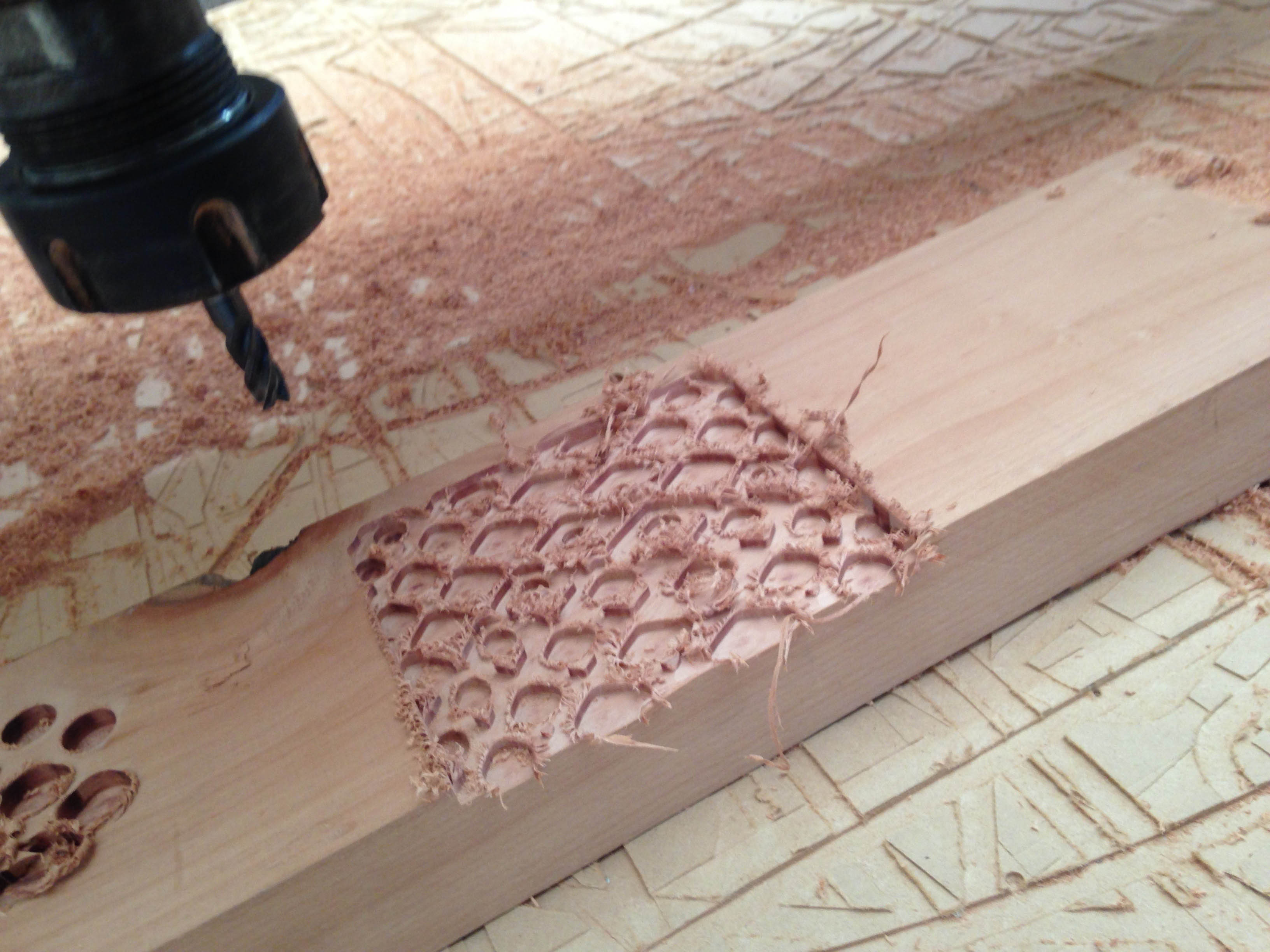
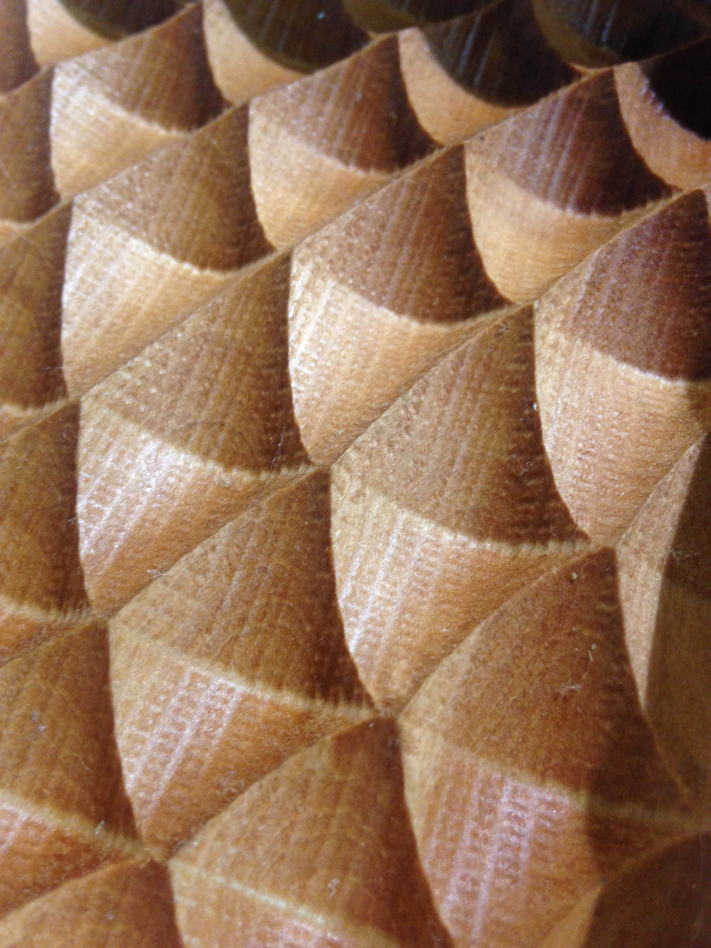
Milling the mold
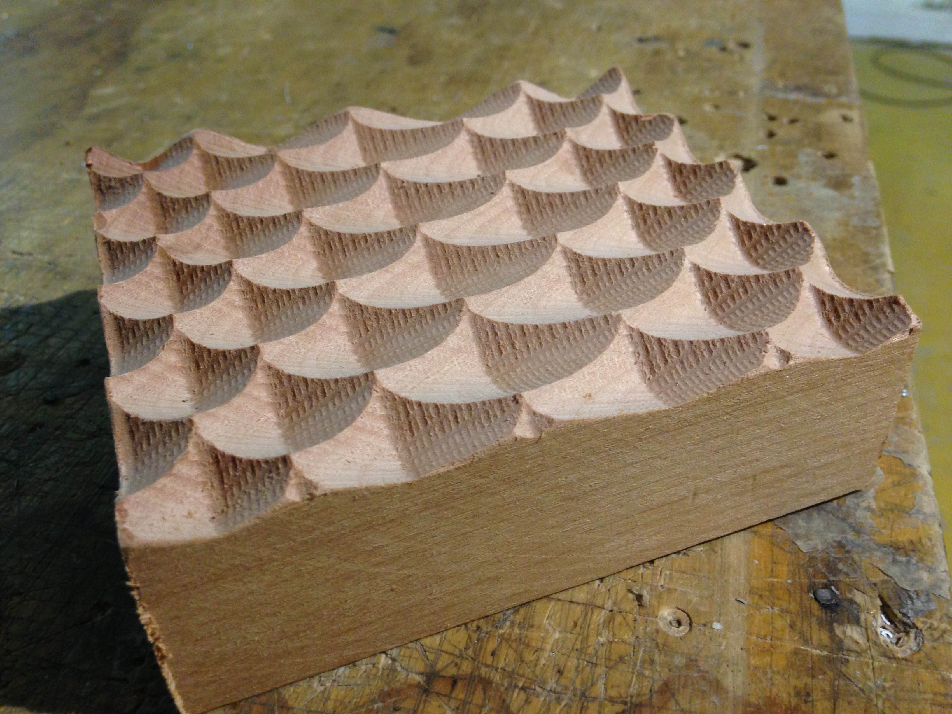
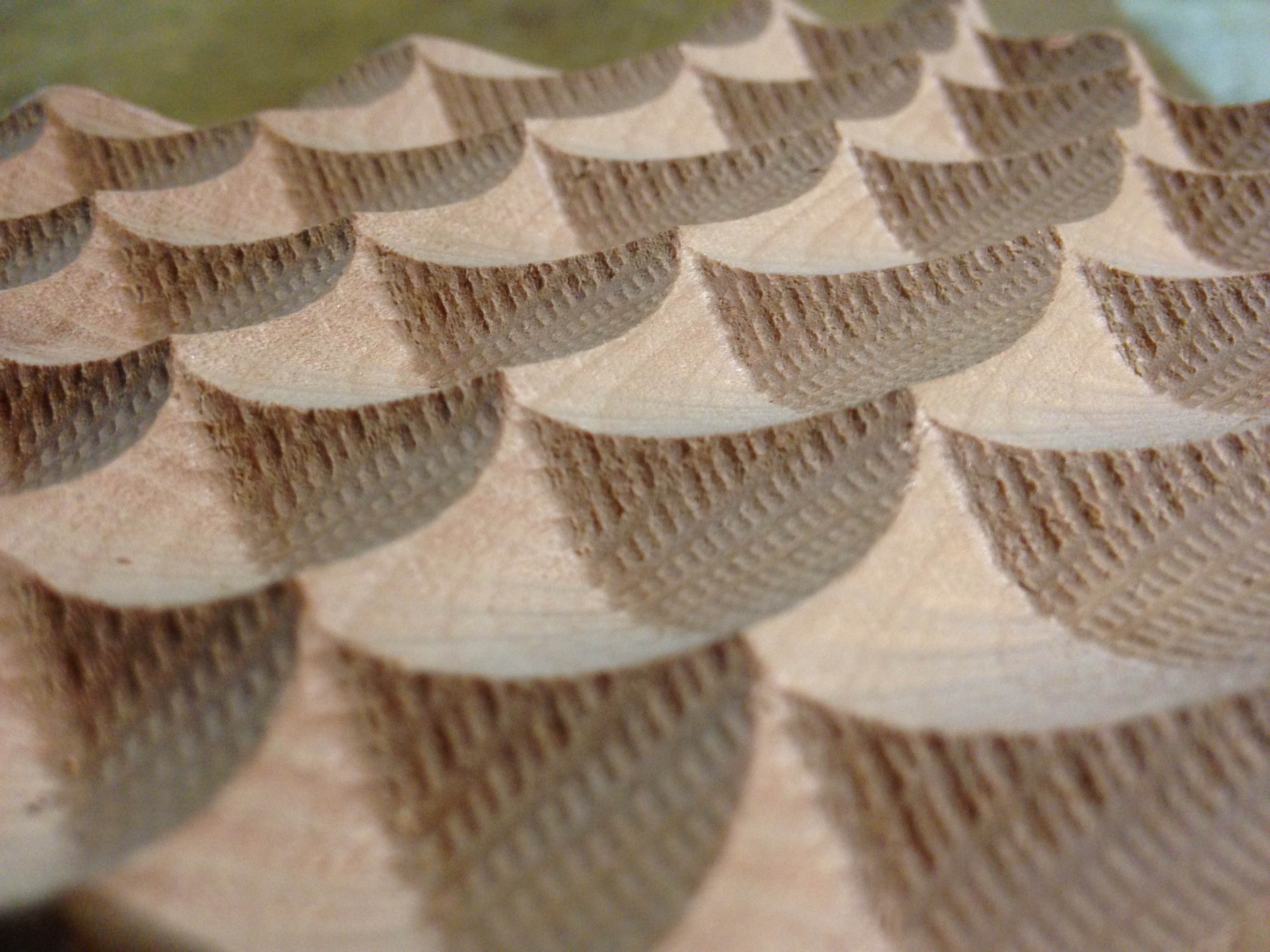
Once obtained the model is sanded, then give it a coat of tung oil.
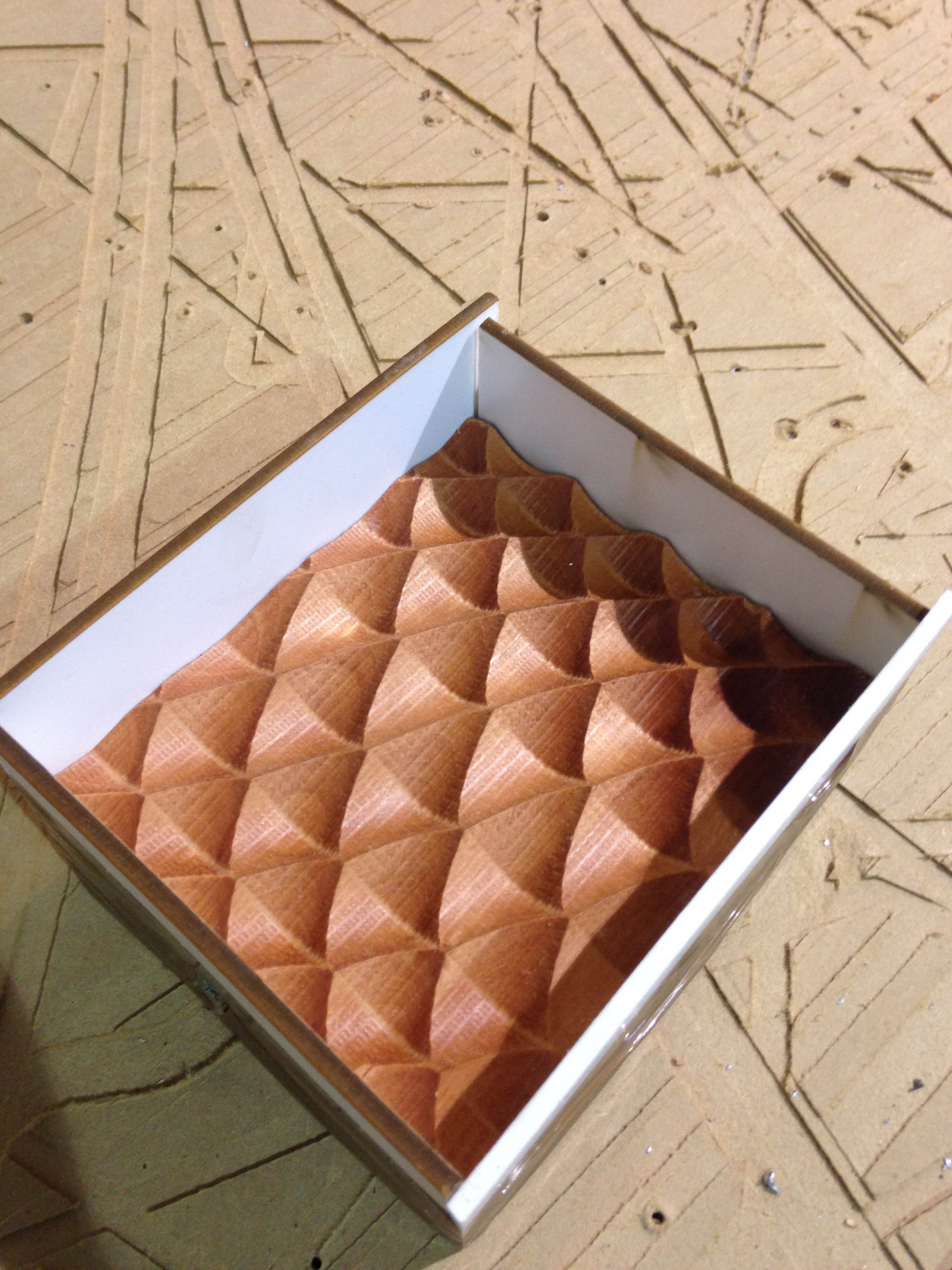
Faces are added to contain silicone casting.
After 24 hours, the sides are removed and repeat the process gesso.
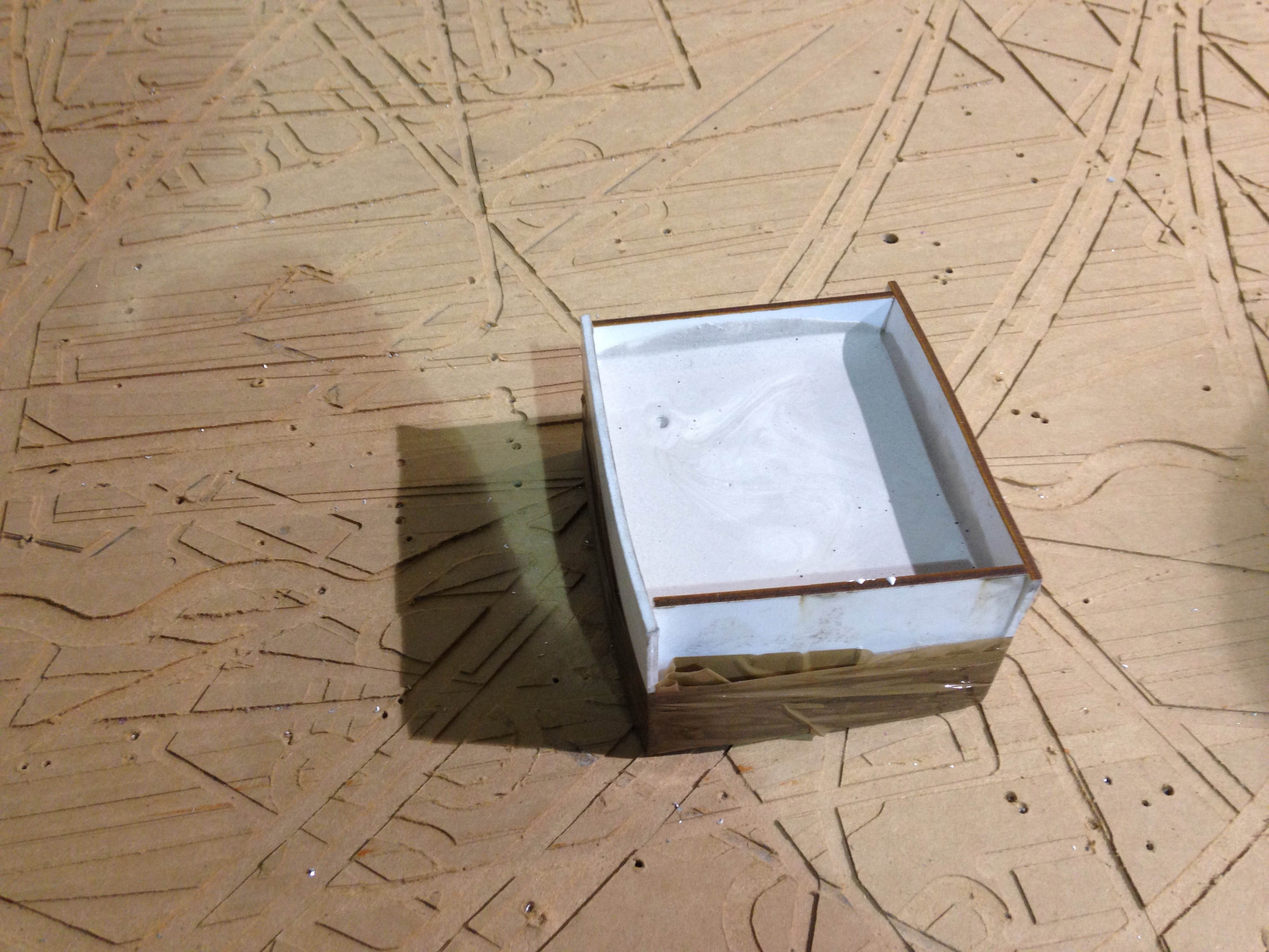
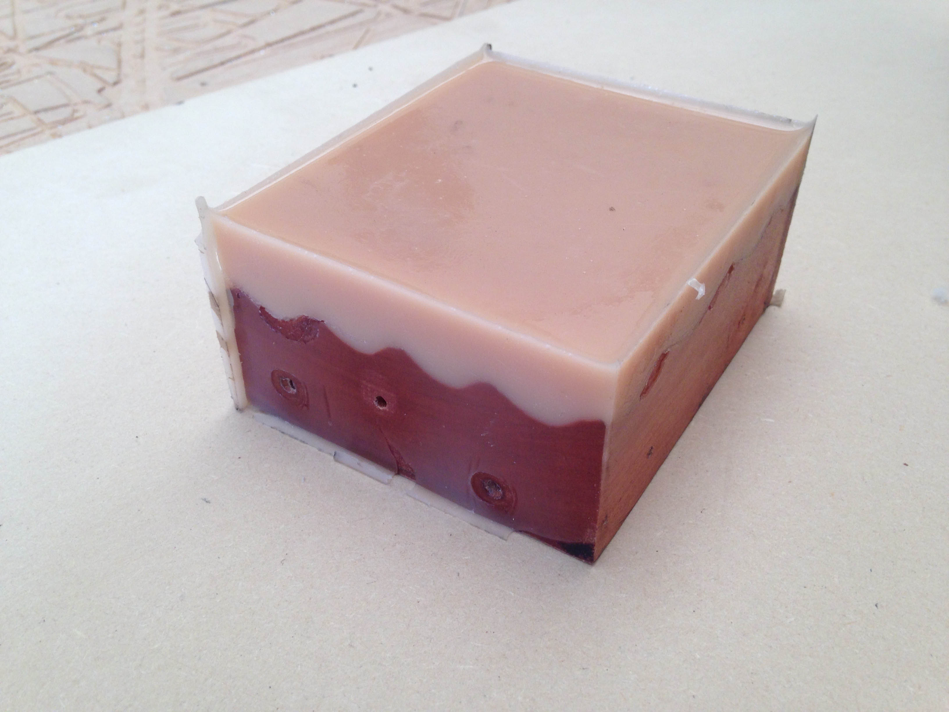
The gesso is delayed approximately one hour set, the demolding is very simple because the mold is flexible.
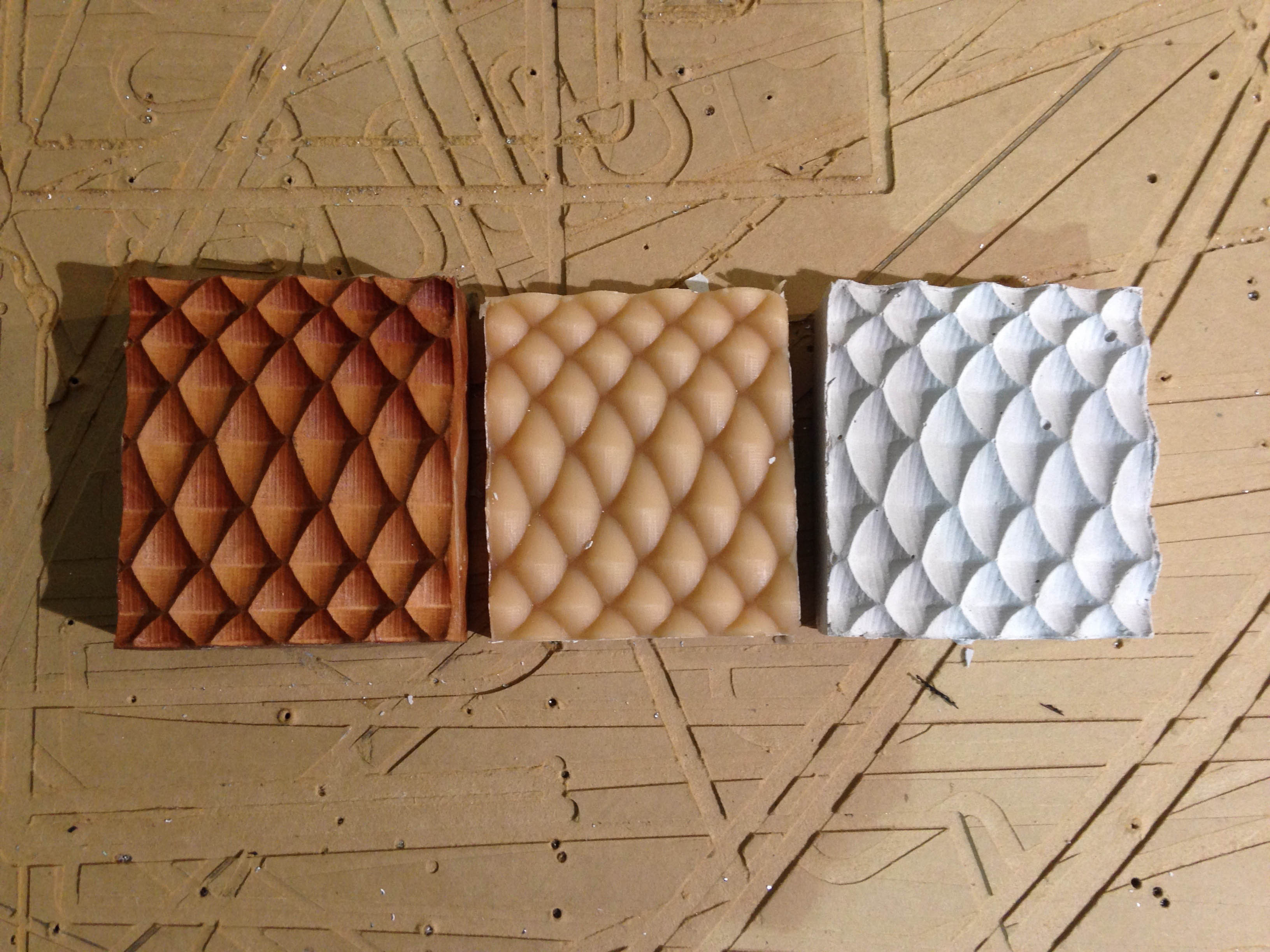
At the end of the process we have the wooden mold, silicone and the final piece of gesso.