Assignment 09
Input Devices
Assignment:
Measure something: add a sensor to a microcontroller that you have designed and read it.
Learning outcomes:
- Demonstrate workflows used in circuit board design and fabrication
- Implement and interpret programming protocols
Have you:
- [ ] Described your design and fabrication process using words/images/screenshots
- [ ] Explained the programming process(es) you used and how the microcontroller datasheet helped you
- [ ] Explained problems and how you fixed them
- [ ] Included original design files and code
This week's recitation
As part of my final project I need a capacitive tracking touchpad to be a sliding interface to a lamp set I'm building. My first attemp will be to reproduce Matt Blackshaw's input devices assignment. Here are the files to reproduce his work. Reproducing this I intend to also work on the interfaces assignment.
Here's also Santi Fuentemilla's work, which can be used as reference since he also made a capacitive interface.
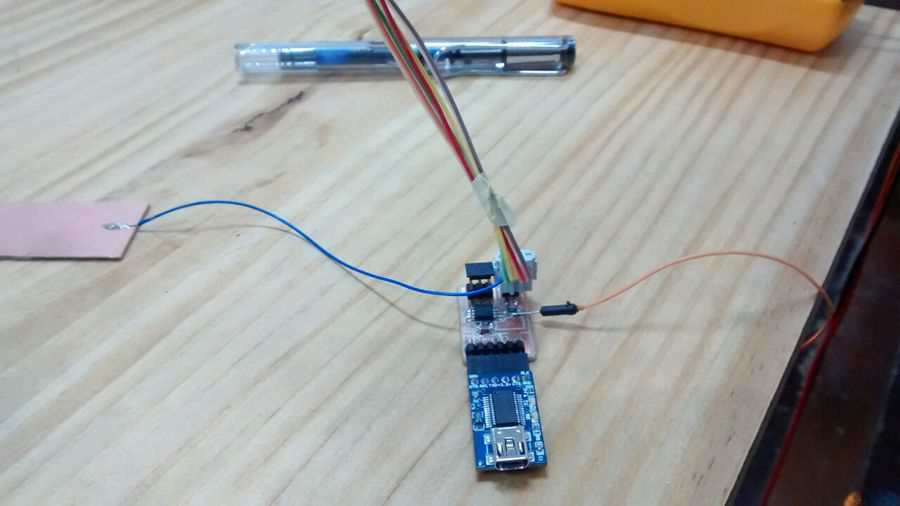
⋮So I started working on the capacitive interface but I'm not sure of how to connect everything ... so, in order to understand the principle (and imitating Matt Blackshaw's example) I went to reproduce Neil's step response example; here are the source files: Python visualization .py, microcontroller .c and microcontroller make file
After a little struggle I got Neil's step response exmple running (it seems that I failed plugging the copper button in the first attempt). By doing this I just wanted to verify how to connect the copper pad, so now I'll go back to my final projects PCB.
Some of the conclusions I can make is that I need to connect the receiving pin to an ADC port (not sure if the pulse source must be on the same port as in the example ... just go with the flow). There's too a tight timming configuration on the source pin (check ADMUX and ADCSRA on the datasheet), but I'll dig deeper on this when I get into the programming phase; by the moment I'm still figuring out the hardware.
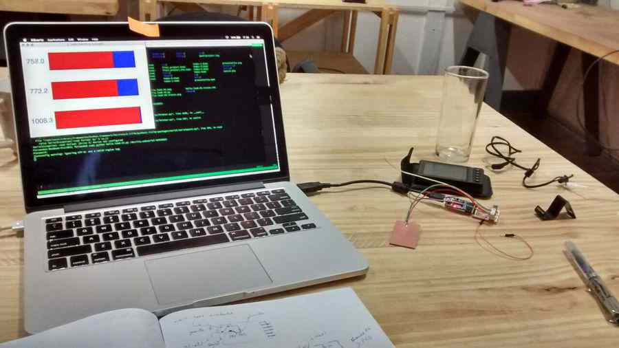
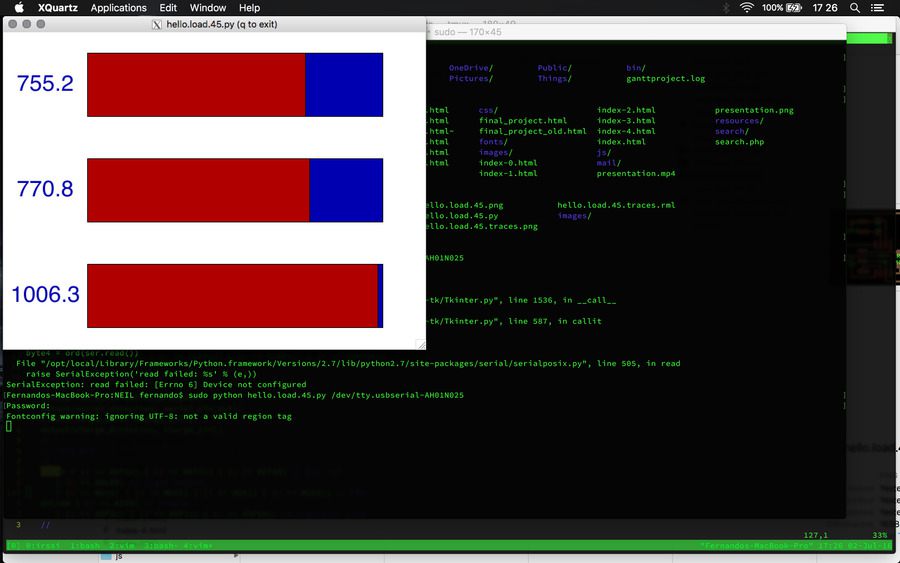
As I'm first trying with the course provided examples (Neil's codes) I'll run the Python script to read the sensor through a FTDI interface.
After installing both the "TKinter" and "serial" packages for Python 2.7 (the installation depends on each system, in my case Macports) and attemping to run the script I got:
$python hello.mag.45.pyTraceback (most recent call last): File "hello.mag.45.py", line 18, inimport serial File "/opt/local/Library/Frameworks/Python.framework/Versions/2.7/lib/python2.7/site-packages/serial/__init__.py", line 13, in from serial.serialutil import * File "/opt/local/Library/Frameworks/Python.framework/Versions/2.7/lib/python2.7/site-packages/serial/serialutil.py", line 10, in import io File "/opt/local/Library/Frameworks/Python.framework/Versions/2.7/lib/python2.7/io.py", line 51, in import _io ImportError: dlopen(/opt/local/Library/Frameworks/Python.framework/Versions/2.7/lib/python2.7/lib-dynload/_io.so, 2): Symbol not found: __PyCodecInfo_GetIncrementalDecoder Referenced from: /opt/local/Library/Frameworks/Python.framework/Versions/2.7/lib/python2.7/lib-dynload/_io.so Expected in: flat namespace in /opt/local/Library/Frameworks/Python.framework/Versions/2.7/lib/python2.7/lib-dynload/_io.so
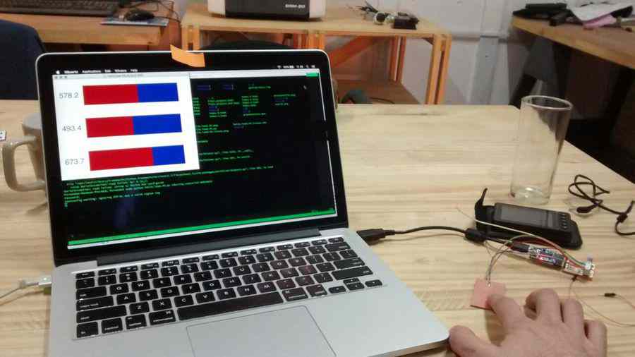
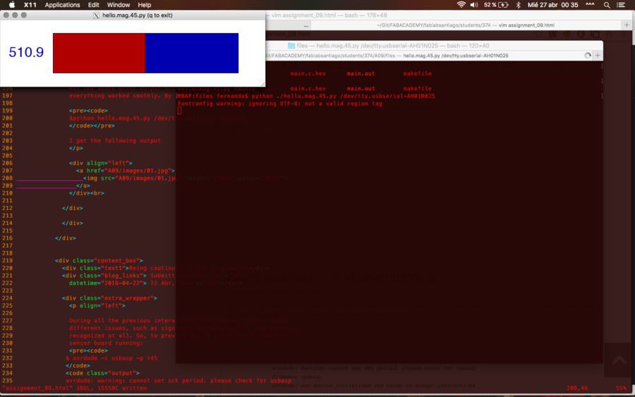
All the above error output disapeared after a reboot ... and everything worked smothly. By running:
$python hello.mag.45.py /dev/tty.usbserial-AH1N025
During all the previous interactions with AVR IC's we've found different issues, such as signature failures or the chip no being recognized at all. So, to prevent this I first tested the hall sensor board running:
So, by checking the backwards the fuses on the online fuse calculator I verified that the IC's fuses have the same settings as the C code, specially the clock (in this case Int. RC Osc. 8MHz) since in many forums I've found that the clock is the one of the main cause of signature issues.$ avrdude -c usbasp -p t45avrdude: warning: cannot set sck period. please check for usbasp firmware update. avrdude: avr device initialized and ready to accept instructions reading | ################################################## | 100% 0.01s avrdude: device signature = 0x1e9206 (probably t45) avrdude: safemode: fuses ok (e:ff, h:df, l:62) avrdude done. thank you.
So, once the clock is verified I compiled the C code with the Makefile and uploaded the .hex file using:
              $ avrdude -P usb -c usbasp -p t45 -U flash:w:main.c.hex


              avrdude: warning: cannot set sck period. please check for usbasp
              firmware update.
              avrdude: AVR device initialized and ready to accept instructions

              Reading | ################################################## |
              100% 0.00s

              avrdude: Device signature = 0x1e9206 (probably t45)
              avrdude: NOTE: "flash" memory has been specified, an erase cycle
              will be performed
              To disable this feature, specify the -D option.
              avrdude: erasing chip
              avrdude: warning: cannot set sck period. please check for
              usbasp firmware update.
              avrdude: reading input file "main.c.hex"
              avrdude: input file main.c.hex auto detected as Intel Hex
              avrdude: writing flash (660 bytes):

              Writing |
              ################################################## | 100%
              0.58s

              avrdude: 660 bytes of flash written
              avrdude: verifying flash memory against main.c.hex:
              avrdude: load data flash data from input file main.c.hex:
              avrdude: input file main.c.hex auto detected as Intel Hex
              avrdude: input file main.c.hex contains 660 bytes
              avrdude: reading on-chip flash data:

              Reading |
              ################################################## | 100%
              0.43s

              avrdude: verifying ...
              avrdude: 660 bytes of flash verified

              avrdude: safemode: Fuses OK (E:FF, H:DF, L:62)

              avrdude done.  Thank you
NOTE: I'm not doing anything yet with the "...cannot set sck perdiod ..." warning,
but here might be
some guidance on how to solve it. Also note that this warning
might be only related with my out-of-date usbasp programmer.
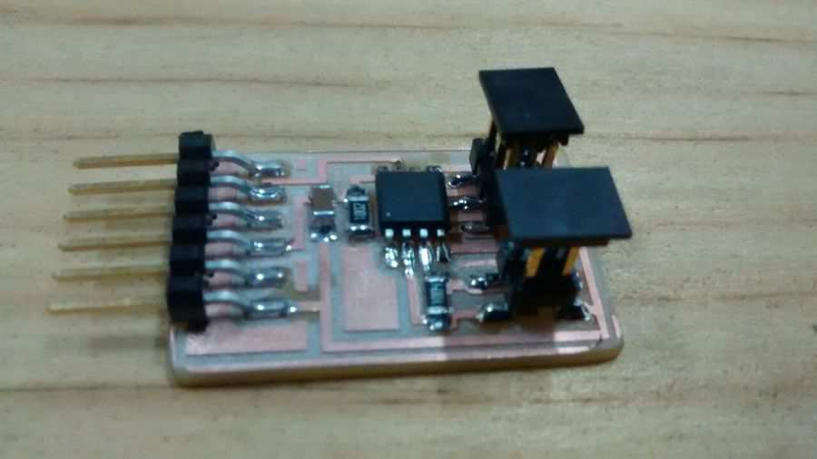
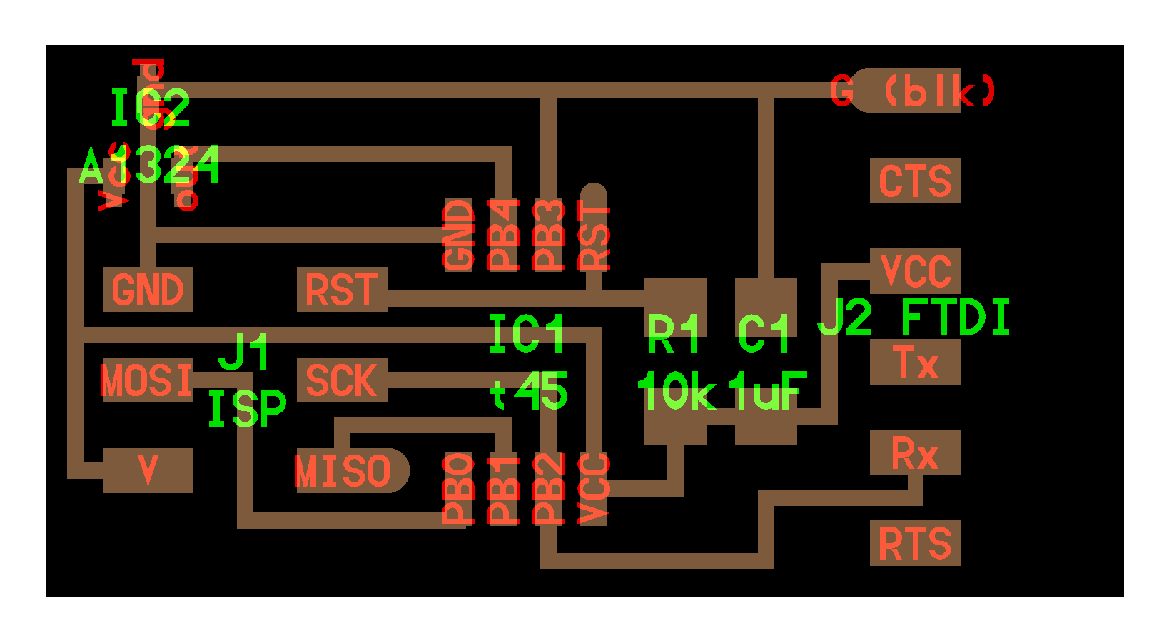
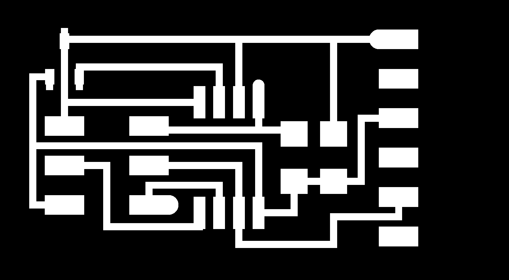
So, with my classmates we decided that each one of us should have many sensor boards to work with, so each one chose one of the already available boards on the class. My chosen sensor (to mill on the board) is the magnetic field sensor. So, my board's links of interest are:
- A photograph of the complete board
- The board components
- Inner milling traces
- Border milling traces
- C code
- Makefile
- Python script
- Java script
- And a couple of videos (link 1, link 2)